
DESCRIPTION
DOCUMENT #
PAGE
SECTION 3
SECTION 2
7 & 10 Amp, Subminiature
30 Amp Miniature
30 Amp, P.C. and Flange mount
30 Amp, P.C.and Flange mount
30 Amp, P.C.and Flange mount
2 Amp, Subminiature
2 AMP, Miniature
5 & 10 AMP, Miniature
3, 5 & 10 AMP, P.C.and Flange Mount
10 & 16 AMP, Miniature
5 Amp, Miniature
44
45, 46
47, 48
49, 50
51, 52
53, 54
55, 56
57, 58
59, 60
61, 62
63
Printed Circuit Board Relays - 1 to 30 Amperes
W78
W67
A314/W250
284
W388/283
W388/283
W389
W389
W97
219
RSX-1800
W21
W88HP
Socket Compatible and General Purpose Relays - 1 to 30 Amperes
SECTION 1
STOCKING DISTRIBUTORS, SALES REPRESENTATIVES & AGENTS
3
CLASS TO CLASS CROSS REFERENCE GUIDE
INSIDE FRONT COVER
340
341
SELECTOR GUIDE
4 - 7
115
116
117
118
120
119
119
121
121
122
123
124
125
126
1, 3, 5, 10 & 15 Amp, P.C. and Solder/Plug-in
3, 5 Amp, P.C. and Solder/Plug-in
10 Amp, Octal Plug-in
10 Amp, Solder Plug-in
General Specifications
11 to 15 Amp, Solder Plug-in and Flange mount
General Specifications & Ratings
30 Amps, Flange Mount
25 Amp, Plug-in and Side Stud mounting
10 Amp, Pin Base Plug-in
5 Amps, Pin Base Plug-in
30 Amps, Plug-in with Polarizing Pin.
10 AMP, Octal Plug-in, Hermetically Sealed
SELECTOR GUIDE
39 - 43
342
109
102
103
104
105
106
107
112
113
114
108
64 - 67
Reed Relays for P.C. Board Applications - 3 VA to 100 VA
PRODUCT INDEX
SELECTOR GUIDE
127
343
128
129
130
130
131
131
132
133
133
134
134
135
136
137
139
138
344
68, 69
70
71
72
73
74
74, 75
76
77
78
79
80
81, 82
83, 84
85, 86
87, 88
89
90
REED
W117
W107,
W171, W172
W171
MRRDL
W172
W101, W104, W131,W134,W193
W101,
W131
W104
W134
W193
MR-Y
MRR & RR
RRN
W102
W120
Application Data
SIP, 0.5 Amp, 4 pin, SPST-NO or NC
DIP, 0.5 Amp, 8 pin, SPST-NO
Specifications
DIP, 0.5 Amp, 8 pin, 1 & 2 pole-NO or NC
DIP, 0.5 Amp, Dual Coil Latch, SPST-N.O.
DIP. 0.5 - 1.0 Amp, SPDT, DPDT
General Specifications
Miniature, 0.5 Amp, 1 to 3 pole NO & Latching
Miniature, 2 Amp, 1 & 2 pole NO Mercury
Miniature, 0.25 Amp,SPDT, DPDT
Miniature, 1.0 Amp, SPDT, DPDT Mercury
Miniature, 0.5 Amp, up to 6 pole NO or 4PDT.
Miniature, 0.5 Amp, with End Terminals
Axial Lead, Shielded, 0.5 Amp,
Open Style Metal Cover/Shield,
Open Style Metal Cover/Shield
Coxial R.F. switching
SELECTOR GUIDE
SECTION 4
91 - 93
Solid State Relays - 2 to 75 Amperes
Application Data
General Specifications
Miniature ,7 Amp, P.C. or Push-on Terminals
Miniature, 1.5 or 3 Amp. P.C Terminals
Miniature, 4 Amp, Spade Terminals, Flange mount
General Specifications
2.5 to 75 Amp. Screw Terminals
Opto Isolator, axial Lead
Embossed Safety Cover
94 - 95
96
97, 98
99, 100
101
102, 103
104 - 107
108
108
140
345
141
142
143
144
145
146
147
147
Solid State Relays
W226, W230, W231
W226
W230
W231
W6
W6
W301T
W6
276
W90
W91
W9A
W92
W7
W60
W178
W49
W76
W1330 & W1335
8 - 12
13 - 15
16 - 18
19, 20
21, 22
23 - 25
26 - 28
29, 30
31, 32
33, 34
35, 36
37
38
PAGE 1
WEBSITE: www.magnecraft.com EMAIL:info@magnecraft.com FAX ON DEMAND 1-800/891-2957, DOCUMENT 100
PAGE 1 & 2, DOCUMENT 100
Magnecraft
Struthers-Dunn

Open Style, 30 Amp , SPDT
Open Style, 30 Amp Power Relay up to 3 pole
Miniature Open Style, 30 Amp, SPST-NO DM
Open Style, 15 Amp, 1 & 2 Pole.
Motor Reversing Contactor, 15 Amp, 3 Pole
Motor Reversing Contactor, 30 Amp, 6 Pole
Solenoid Style Contactor, SPST-DM, 50 to 200 Amps
Ground Fault Interrupt (GFI), 20 Amp, DPDT
General Specifications & Application Data
Mercury Displacement relays 30 to 100 Amp
Solinoid Style Lighting Contactor 100 & 200 Amps
Application Data
Octal Style, 10 Amp
Octal Style ,Programmable, 10 Amp,
Miniature, 5 Amp
Repeat Cycle, 10 Amps,
Square base, 12Amp,Solder/plug-in or Flange
1 - 3 pole, 10 Amps, Solder/Plug-in, flange panel screw.
Octal 1 -3 Pole, 10 Amp,
Industrial Plug-in with Locking Clip. 10 Amps,
Industrial Plug-in with Locking Clip. 10 Amps,
Current Sensor, 10 Amps, Plug-in or Screw panel mount
Voltage Sensor, 10 Amps, up to 400 HZ 1-3 Phase
Voltage Sensor, 10-13 Amps, Solder/Plug-in or Octal
DESCRIPTION
PAGE
SECTION 5
SELECTOR GUIDE
148
Time Delay Relays and Sensors
DOCUMENT #
PAGE 2
WEBSITE: www.magnecraft.com EMAIL:info@magnecraft.com FAX ON DEMAND 1-800/891-2957, DOCUMENT 100
109 - 112
SECTION 7
Sequence & Latching
W250ML
W388ML/285
308
B255
W88L
311
C85
SELECTOR GUIDE
166 - 168
172
Application Data
Octal Base, Magnetic Latching, 10 Amps
Latching, 10 Amp, Solder/Plug-in
Latching, 10 Amp, 4 Pole. Solder/Plug-in
Mechanical Latch, 10 Amps, Pin base Plug-in
Open or Enclosed Mechanical Latch,10 Amp
Plug-in Sequence (Stepper), 5 Amp
Open Style, Sequence (Stepper) 20 Amp
Time Delay Relays
W211
W211PROG
W67
W222
W388
286/287
326, 327
236, 237 & 238
246, 247
W235
349
W236
149
151
150
152
153
154
346
347
348
157
158
159
160
SECTION 6
SELECTOR GUIDE
161
Relays and Contactors - 15 to 200 Amperes
136 - 139
W199
425
W88UKD
415
275
575
101, 102, 103
214
MDR
MDR
102, 103
162
163
170
171
166
167
168
169
164
165
349
350
177
173
174
175
176
179
180
Latching, Sequence and Stepper Relays
169
170
171, 172
173, 174
175, 176
177, 178
179
180
SECTION 11
206
UTILIZATION CATAGORIES
CE
Customer Service Staff
199
198
207
INSIDE BACK COVER
Utilization Categories
Staff Directory
SECTION 10
SELECTOR GUIDE
188
Sockets and Accessories
70--464-1, 70-465-1
70-459-1, 70-461-1
70-378-1, 70-401-1, 70-379-1, 70-402-1,
70-463-1
70-124-1 & -2, 70-178-1 & -2
27390, 33377
70-475, 70-478
70-303-1 THRU 70-310-1
70-312
70-276
195
196
197, 198
199
200
201
202
203, 204
205
205
189
191
191
192
193
197
196
190
195
195
192 - 194
Series A314/250, 8 & 11 Pin Octal, Panel/DIN mount
CLASS 78 Panel/DIN mount
Class 78, Chassis, P.C.,
Class 388/283 Style, Panel/DIN Mount
Class 388/283 Style, Chassis Mount or P.C.
Series 219 style, Panel mount, screw terminal
Class 76 Style, Panel/DIN mount
Class 67 chassis mount
Class 97 Style, Chassis mount
DIP Style, 14 Pin
SECTION 9
SELECTOR GUIDE
185, 186
Sensitive Relays, Low Input Power
112, 112PGF
67S
392
292
184
Low Power, 2 Amps, Pin Base Plug-in w/ locking clip
Miniature Sensitive, 3 Amps, 2 - 6 Poles.
Sensitive, Octal Plug-in, 5 Amps, 1 - 3 Poles
Solder/plug-in, 5 Amps, 1 - 3 Poles
185
351
186
187
187, 188
189
190
191
SECTION 8
SELECTOR GUIDE
181, 182
Hi- Voltage Relays - 2,500 to 10,000 Volts
158
102HV
183
184
181
182
183
Open Style, 200 mA, 5000Vdc
Encapsulated Reed, 10-30mA, up to 10kv
113, 114
115, 116
117
118
119
120 - 124
125, 126
127, 128
129 - 130
131
132
133
134, 135
140 - 146
147
148
149, 150
151, 152
153, 154
155, 156
157
158, 159
160 - 164
165
WEBSITE: www.magnecraft.com EMAIL:info@magnecraft.com FAX ON DEMAND 1-800/891-2957, DOCUMENT 100
Magnecraft
Struthers-Dunn
PAGE 3
UNITED STATES DOCUMENT NUMBERS SHOWN INSIDE THE STATES.
359
356
354
355
357
358
360
362
363
367
364
361
365
368
369
370
366
DOCUMENT NUMBER OUTSIDE THE U.S. & CANADA:
352
PLEASE DIAL 800-891-2957
FOR AN UP-TO-DATE DIRECTORY FOR YOUR AREA.
WHEN PROMPTED, PLEASE ENTER THE APPROPRIATE
DOCUMENT NUMBER FROM THE MAP BELOW.
@
STOCKING DISTRIBUTORS.
STOCKING DISTRIBUTORS.
STOCKING DISTRIBUTORS.
STOCKING DISTRIBUTORS.
STOCKING DISTRIBUTORS.
@
FACTORY DIRECT FIELD SALES PROFESSIONALS.
FACTORY DIRECT FIELD SALES PROFESSIONALS.
FACTORY DIRECT FIELD SALES PROFESSIONALS.
FACTORY DIRECT FIELD SALES PROFESSIONALS.
FACTORY DIRECT FIELD SALES PROFESSIONALS.
@
U.S. AND INTERNATIONAL AGENTS.
U.S. AND INTERNATIONAL AGENTS.
U.S. AND INTERNATIONAL AGENTS.
U.S. AND INTERNATIONAL AGENTS.
U.S. AND INTERNATIONAL AGENTS.
FAX ON DEMAND DIRECTORY
CANADA DOCUMENT NUMBER:
353

Page 4
1
SOCKET COMPATIBLE
AND
FLANGE MOUNTED
GENERAL PURPOSE RELAYS
2 TO 30 AMPERES
S E C T I O N
1
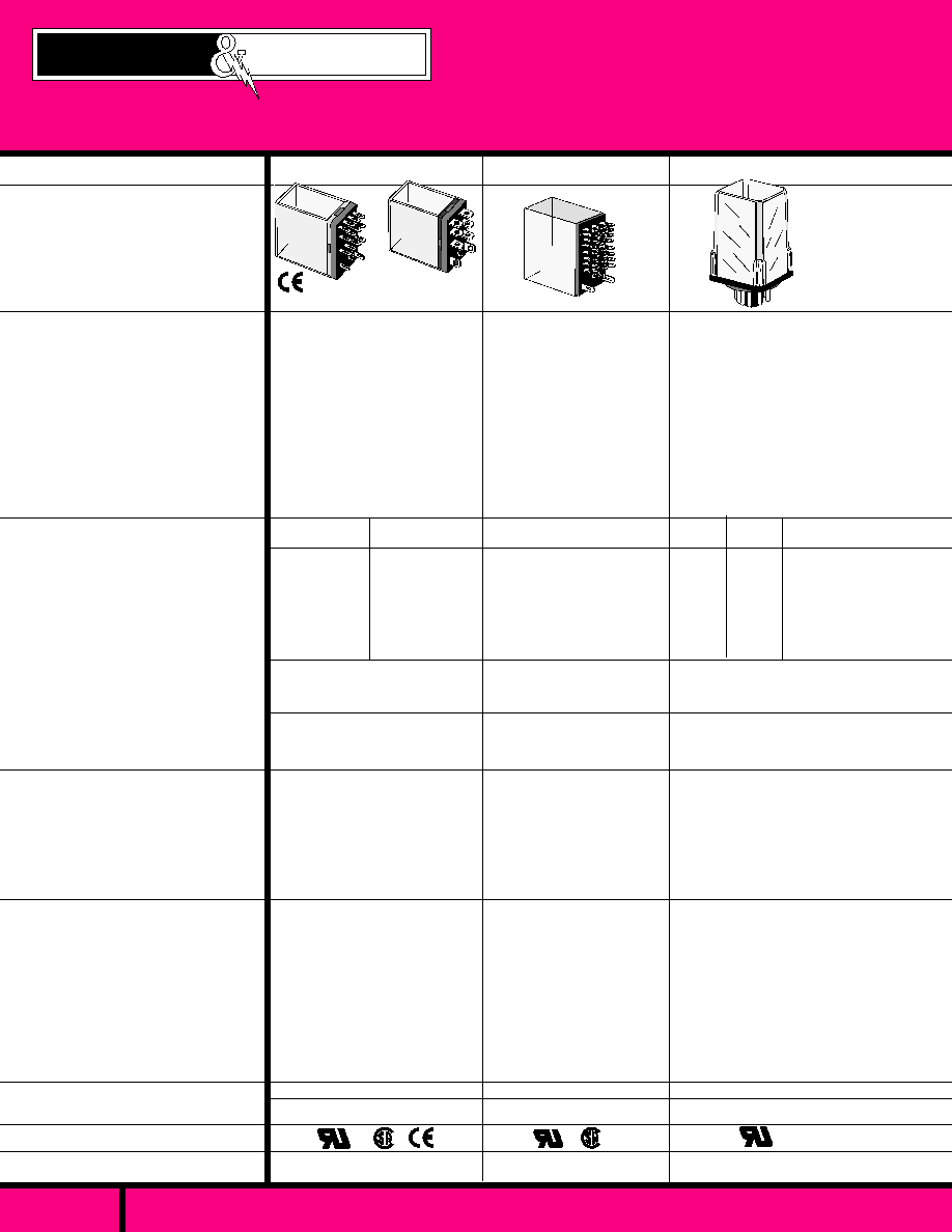
A314/250
H W L
1.37 X 1.37 X 2.25
24, 120 & 240 VAC
12, & 24 VDC
2.75 VA
1.2 WATTS
1500 V rms
120 VAC
5, 12, 24, 48 &115 VDC
2.5 VA
2 WATTS
H W L
SPDT TO 8PDT
STANDARD CONTACTS
5 AMP
BIFURCATED CONTACTS
3 AMP
AT 120VAC/32VDC
SILVER, GOLD OVERLAY
50 MILLIOHMS (INITIAL)
1500 V rms
H W L
6, 12, 24,120 & 240 VAC
6, 12, 24, 48 & 110 VDC
1.2 VA
0.9 WATTS
1500 V rms
- 40� C to + 70� C
25 MILLISECONDS
25 MILLISECONDS
AC- 50M, - DC-100M OPER'S.
200,000 OPERATIONS .
.858 X 1.10 X 1.40
POLYCARBONATE DUST COVER.
SOLDER/PLUG-IN OR PC BOARD
MOUNTING
INDUSTRY STANDARD FOOT-
PRINTS.
UP TO 8 POLES WITH STANDARD
OR BIFURCATED CONTACTS.
CHASSIS OR PC STYLE
SOCKETS AVAILABLE.
PAGE 8 THRU 12
PAGE 16 THRU 18
SPDT, DPDT
15 &10
AMPS
A T
120/240 VAC
C US
QUALIFIED
SILVER CADMIUM OXIDE,
( GOLD FLASHED)
50 MILLIOHMS (INITIAL)
RELAY SERIES
FEATURES
CONTACT DATA
COIL DATA
GENERAL DATA
APPROVALS
INSULATION
CHARACTERISTICS
DIELECTRIC STRENGTH
PAGE NUMBER
SEE SECTION 10
FOR MATING SOCKETS
WEBSITE: www.magnecraft.com EMAIL:info@magnecraft.com FAX ON DEMAND 1-800/891-2957, DOCUMENT 100
ISO 9002
QS 9000
ISO 9002
QS 9000
4PDT
1, 3 & 5
AMPS
AT
120/240 VAC
C US
PAGE 13 THRU 15
POLYCARBONATE DUST COVER
SOLDER/PLUG-IN OR PC BOARD
MOUNTING.
INDUSTRY STANDARD FOOTPRINTS.
UP TO 4 POLES WITH STANDARD OR
BIFURCATED CONTACTS, INDICATOR
LAMP AND PUSH BUTTON,
TOP FLANGE COVER , PANEL/DIN,
CHASSIS OR P.C STYLE SOCKETS
AVAILABLE.
POLYCARBONATE DUST COVER
8 OR 11 PIN OCTAL PLUG-IN
INDUSTRY STANDARD FOOT-
PRINTS
INDICATOR LAMP AND PUSH
BUTTON AVAILABLE.
PANEL/DIN STYLE SOCKETS
AVAILABLE.
1.20 X .735 X -
- 55� C to + 70� C
- 55�C to + 105�C
18 MILLISECONDS
8 MILLISECONDS
10 MILLION OPERATIONS
100,000 OPERATIONS
- 10� C to + 50� C (AC)
- 10� C to + 60� C (DC)
- 30� C to + 105� C
25 MILLISECONDS
20 MILLISECONDS
10 MILLION OPERATIONS
100,000 OPERATIONS
3PDT
1 0
A M P S
A T
240 VAC
DPDT
1 2
A M P S
AT
120 VAC
SPDT
1 2
A M P S
AT
120 VAC
DIMENSIONS
CONTACT CONFIGURATION:
MAXIMUM ALLOWABLE
CONTACT LOAD:
CONTACT MATERIAL:
CONTACT RESISTANCE:
AC - VOLTAGE:
DC - VOLTAGE:
P O W E R :
VA,: (VAC)
WATTS,: (VDC)
AMBIENT TEMPERATURE
OPERATIONAL:
STORAGE:
TIMING VALUES
MAX. OPERATE:
MAX. RELEASE:
L I F E
MECHANICAL:
ELECTRICAL:
SOCKET COMPATIBLE
78
67
SILVER, GOLD PLATED - 1A
SILVER, GOLD FLASHED - 3A
SILVER CADMIUM OXIDE - 5, 10 & 15A
50 & 100 MILLIOHMS MAX
PAGE 5
Magnecraft
Struthers-Dunn

SOCKET COMPATIBLE & FLANGE MOUNT
WEBSITE: www.magnecraft.com EMAIL:info@magnecraft.com FAX ON DEMAND 1-800/891-2957, DOCUMENT 100
24, 120 & 240 VAC
12, & 24 VDC
3.5 VA
1.44 WATTS
- 30� C to + 50� C (AC)
- 30� C to + 65� C (DC)
- 30� C to + 100� C
20 MILLISECONDS
20 MILLISECONDS
5 MILLION OPERATIONS
100,000 OPERATIONS
389
PAGE 26 THRU 30
388 & 283
SILVER CADMIUM OXIDE,
( GOLD FLASHED)
50 MILLIOHMS (INITIAL)
1.40 X 1.53 X 1.90
388B STYLES RATED UP
TO 10 AMPS AT 150 VDC.
SPDT
13 AMPS
AT
240 VAC
3PDT
11 AMPS
AT
240 VAC
POLYCARBONATE DUST COVER.
3/16" SOLDER/PLUG-IN, FLANGE OR PC
BOARD MOUNTING
INDUSTRY STANDARD
FOOTPRINTS.
WIDE SELECTION OFPANEL/DIN,
CHASSIS & P.C. STYLE SOCKETS
15 AMP VERSIONS & TOP FLANGE
COVERS AVAILABLE.
QUALIFIED
PAGE 21 THRU 25
24, 120 & 240 VAC
12, 24 & 120 VDC
2.75 VA
1.2 WATTS
2000 V rms
- 30� C to + 50� C (AC)
- 30� C to + 65� C (DC)
- 30� C to + 100� C
24 MILLISECONDS
30 MILLISECONDS
5 MILLION OPERATIONS
100,000 OPERATIONS
ISO 9002
QS 9000
DPDT
12 AMPS
AT
240 VAC
SILVER CADMIUM OXIDE,
SILVER OR GOLD DIFFUSED
50 MILLIOHMS (INITIAL)
1500 V rms
- 45� C to + 45� C (AC, COVR..)
- 45� C to + 70� C (DC, COVR)
- 45� C to + 85� C (DC, OPEN)
15 MILLISECONDS
10 MILLISECONDS
10 MILLION OPERATIONS
100,000 OPERATIONS
284
4 P D T
MAX TOTAL LOAD 30
AMPS @ 120 VAC,
20 AMPS @ 240 VAC
10 AMPS PER POLE
NOT TO EXCEED 30
A M P S
6, 12, 24, 48, 120 & 240 VAC
6, 12, 24, 48, 115-125 VDC
3.4 VA
1.9 WATTS
PAGE 19, 20
H W L
1.50 X 1.93 X 1.87
C US
C US
S P D T ,
D P D T
25 AMPS @
300 VAC
3PDT
20 AMPS @
150 VAC
30 AMPS @
300 VAC
ISO 9002
QS 9000
QUALIFIED
POLYCARBONATE
FLANGED DUST COVER.
1/4" Q.C./SOLDER LUG
TERMINALS FOR QUICK
CONNECT.
INDUSTRY STANDARD
FOOTPRINTS
TOP FLANGE COVER
AVAILABLE.
(DM-DB)
SPDT-NO-NC
SILVER CADMIUM OXIDE
50 MILLIOHMS (INITIAL)
2200 V rms
POLYCARBONATE DUST COVER.
3/16" SOLDER/PLUG-IN, OR PC
BOARD MOUNTING
INDUSTRY STANDARD FOOTPRINT.
CAPABLE OF SWITCHING UP TO 30
A M P S .
WIDE CHOICE OF OPTIONS.
2000 V rms
24, 120 & 240 VAC
12, 24 & 120 VDC
8 VA
3 WATTS
- 20� C to + 50� C
35 MILLISECONDS
35 MILLISECONDS
5 MILLION OPERATIONS
100,000 OPERATIONS
SILVER ALLOY
50 MILLIOHMS, (INITIAL)
H W L
25 AMPS @
120 VAC/28VDC
TUNG. LAMP 25A,
120VAC
DPDT NO-NC (DM-DB)
PAGE 31, 32
1.56 X 1.56 X 2.06
1.40 X 1.53 X 1.90
H W L
H W L
97
METAL DUST COVER
1/4" BRASS CONTACT
TERMINALS
DPDT-NO-NC
(DM-DB) CONTACTS
CHOICE OF MOUNTING
MATING SOCKETS
PAGE 6
Magnecraft
Struthers-Dunn

SOCKET COMPATIBLE
PAGE 7
WEBSITE: www.magnecraft.com EMAIL:info@magnecraft.com FAX ON DEMAND 1-800/891-2957, DOCUMENT 100
1500 V rms
H W L
1500 V rms
1500 V rms
SILVER CADMIUM OXIDE
50 MILLIOHMS (INITIAL)
.2.47 X 1.85 X 2.84
H W L
H W L
PAGE 33, 34
PAGE 37
PAGE 38
C US
1.53 X 1.53X 2.03
.2.62 X 1.468 X 2.593
88HP
21
RSX-1800
SILVER CADMIUM OXIDE
50 MILLIOHMS (INITIAL)
SILVER ALLOY
100 MILLIOHMS (INITIAL)
219
SILVER CADMIUM OXIDE,
GOLD DIFFUSED
50 MILLIOHMS (INITIAL)
VARIOUS COMBINATIONS
PAGE NUMBER
APPROVALS
DIMENSIONS
.2.62 X 1.468 X .2.593
H W L
GENERAL DATA
AMBIENT TEMPERATURE
OPERATIONAL:
STORAGE:
TIMING VALUES
MAX. OPERATE:
MAX. RELEASE:
L I F E
MECHANICAL:
ELECTRICAL:
COIL DATA
AC - VOLTAGE:
DC - VOLTAGE:
P O W E R :
VA,: (VAC)
WATTS,: (VDC)
INSULATION
CHARACTERISTICS
DIELECTRIC STRENGTH
CONTACT DATA
FEATURES
SEE SECTION 10
FOR MATING SOCKETS
RELAY SERIES
6, 12, 24, 120 & 240 AC
6,12, 24(28),32,115(125)DC
5 VA
1.8 WATTS
6, 12, 24 & 120 VAC
6, 12, 24 & 110-125 VDC
5 VA
1.8 WATTS
120 VAC
OPTIONAL VDC
4 & 8 VA
-
120 VAC
12, 24 VDC
3.0 VA
1.5 WATTS
1500 V rms
2 PAIR of DPDT or 3PDT
CONTACT CONFIGURATION:
MAXIMUM ALLOWABLE
CONTACT LOAD:
CONTACT MATERIAL:
CONTACT RESISTANCE:
POLYCARBONATE DUST
COVER
MEETS NEMA STD. TS 2-
1992
APPROVED BY D.O.T
INDUSTRY STANDARD
FOOTPRINT
POLYCARBONATE DUST
COVER
12 PIN STYLES PERFORMS
BASIC FUNCTIONS OF AN
ALARM POINT
OPERATES FROM AN N.O.
OR N.C. TROUBLE CONTACT
MATING SOCKETS AVAILABLE
POLYCARBONATE DUST
COVER
12 OR 14 PIN STYLES
ENCAPSULATED COIL
WIDE CHOICE OF CONTACT
COMBINATIONS.
LARGE CHOICE OF
OPTIONS
MATING SOCKETS
AVAILABLE
HERMETICALLY SEALED
STEEL ENCLOSURE
10 AMP AND 12 AMP
CONTACTS
8 OR 11 PIN OCTAL
BASE.
PAGE 35, 36
- 10� C to + 60� C
25 MILLISECONDS
20 MILLISECONDS
20 MILLION OPERATIONS
100,000 OPERATIONS
- 10� C to + 70� C
25 MILLISECONDS
20 MILLISECONDS
20 MILLION OPERATIONS
500,000 OPERATIONS
- 40� C to + 84� C
25 MILLISECONDS
25 MILLISECONDS
5 MILLION OPERATIONS
250,000 OPERATIONS
- 10�C to + 50�C (AC),
- 10�C to + 60�C (DC),
-30�C to + 105�C
25 MILLISECONDS
20 MILLISECONDS
5 MILLION OPERATIONS
100,000 OPERATIONS
10 AMPS @
240 VAC/28 VDC
Available with Make
Before Break contacts
10 AMPS @
120VAC, 28 VDC
20 AMPS @
120/240 VAC, 28 VDC
20 AMPS, 120VAC
TUNGSTEN
(2 POLE)
12 AMPS @ 120VAC
8 AMPS @ 240 VAC
(3 POLE)
10 AMPS @ 120VAC
6 AMPS @ 240 VAC
DPDT, 3PDT
DPDT
Magnecraft
Struthers-Dunn

C US
Recognized Component mark for
Canada and the United States.
UL Recognized
File No. E52197
MANUFACTURED UNDER QUALITY SYSTEM
ISO 9002 & QS 9000
COIL
Pull-in Voltage:
Dropout:
Max. Voltage:
Coil Resistance:
Coil Insulation:
Maximum tolerable coil
dissipation:
Duty:
CONTACTS
Contact Configurations:
Contact Material:
Contact Resistance:
Contact Rating:
TIMING
Operate Time:
Release Time:
DIELECTRIC STRENGTH
Coil to Frame:
Across Open Contacts:
Contact to Frame:
Insulation Resistance:
TEMPERATURE
Ambient Temperature:
VIBRATION RESISTANCE
Functional:
,
SHOCK RESISTANCE
Mechanical Durability:
Malfunction Durability:
LIFE EXPECTANCY
Mechanical (No Load):
Electrical (rated Load):
MISCELLANEOUS
Enclosure:
Weight:
75% of Nominal Voltage or less for DC, 80% of nominal or less for AC.
DC -10% min., AC - 30% min.
110%
�
15% AC & DC
Class "B" coil insulation system (130�C per UL standard 1446)
2.3 Watts DC, 2.55 VA (60Hz) AC, approx. 5 minutes max. @ 40�C
Continuous
SPDT, DPDT, 4PDT.
1 Amp Bifurcated Silver Gold plated. 3 AMP Silver Gold flashed
5 Amp, Silver Cadmium Oxide. 10 & 15 AMP, Silver Cadmium Oxide.
100 Milliohms Max.(3, 5, 10 & 15AMP) @ 6V, 1 AMP
50 Milliohms Max. ( 1 AMP) @ 6V, 0.1 AMP
4PDT- Bifurcated 1Amp @ 120/240 VAC 30VDC. 1/16HP (2.8A FLA), 120VAC.
Pilot duty - 5A make, 1/2A break, 1 A continuous, 120 VAC
4PDT- 3 Amps @ 120/240 VAC, 30VDC, 1/10HP 120/240VAC, C300 pilot duty.
4PDT- 5 Amps @ 120/240 VAC, 30VDC, 1/6 HP 120/240VAC, C300 pilot duty
DPDT -10 Amps @ 120/240VAC, 30VDC.1/3 HP,120VAC. 1/2HP 240VAC.
SPDT -15 Amps @ 120/240VAC, 30VDC.1/3 HP 120VAC, 1/2 HP 240VAC.
25mS Max. @ Nominal Voltage.
25 mS Max. @ Nominal Voltage.
1500 V rms
1000 V rms
1500 V rms
100 Megohms Min. @ 500 VDC.
-40�C to + 70�C @ Rated Operation
10 to 55 Hz; 1mm ( Double Amplitude).
Mechanical Durability, 1000 m/s
2
(approx.100 G ).
Malfunction Durability, 200 m/s
2
(approx. 20 G ).
10,000,000 Operations (AC & DC).
200,000 Operations Min. (at rated Resistive load).
Clear Polycarbonate Dust Cover, Molded.
SPDT & DPDT 1.41 oz, (Approx. 40 g) , 4PDT 2.47 oz. (Approx. 70 g).
SPECIFICATIONS CLASS 78
NEW
EPOXY SEALED VERSIONS
AVAILABLE. CONSULT FACTORY.
78
ICE CUBE STYLE SOLDER/PLUG-IN OR PC BOARD RELAY
C L A S S
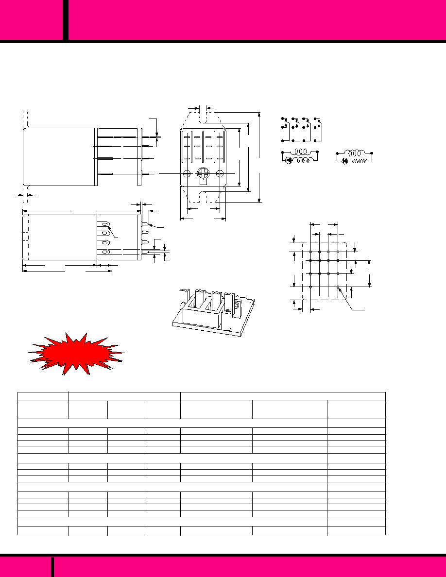
W78APCX & PCX
4PDT, PRINTED CIRCUIT
1, 3 OR 5 AMP
W78ARPCX & RPCX
SPDT, DPDT, SOLDER/PLUG-IN
10 OR 15 AMP
W78ARCSX & RCSX
SPDT, DPDT, SOLDER/PLUG-IN
10 OR 15 AMP
W78ACSX & CSX
4PDT, SOLDER/PLUG-IN
1, 3 OR 5 AMP
COMPLIES WITH
REQUIREMENTS OF
IEC STANDARDS
947-4-1 AND 947-5-1
LOW VOLTAGE DIRECTIVE
IEC = INTERNATIONAL
ELECTROTECHNICAL COMMISSION
*
*
*
RELEVANT IEC CONTACT UTILIZATION CATEGORIES
AC-1, AC-3, DC-1, AC-15
(SEE SECTION 11 FOR RELEVANT UTILIZATION CATEGORIES.)
PAGE 8
WEBSITE: www.magnecraft.com EMAIL:info@magnecraft.com FAX ON DEMAND 1-800/891-2957, DOCUMENT 100
WEBSITE: www.magnecraft.com EMAIL:info@magnecraft.com FAX ON DEMAND 1-800/891-2957, DOCUMENT 100
9
5
1
6
2
11
7
3
12
4
8
10
14
13
(-)
(+)
Observe polarity
when L.E.D. Indicator
is installed across
coil. ( DC Styles Typ.)
AC STYLES
DC STYLES
13
14
OR
OUTLINE DIMENSIONS
Dimensions shown in INCHES and (MILLIMETERS)
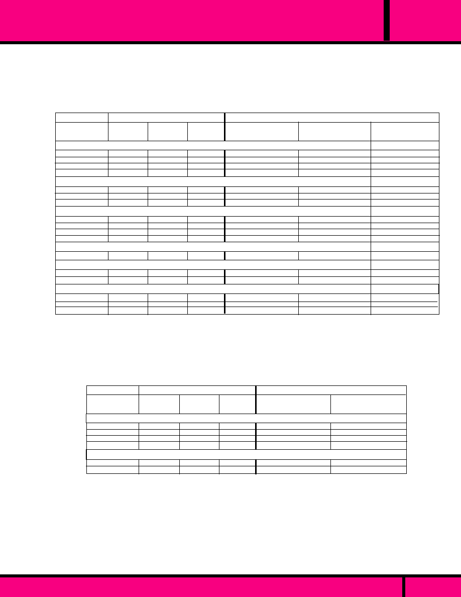
DC OPERATED COIL - SOLDER/PLUG-IN STYLE
AC OPERATED COIL - SOLDER/PLUG-IN STYLE.
W78ATCSX-2
W78ATCSX-3
W78ATCSX-5
W78ATCSX-6
W78ANTCSX-4
W78ANTCSX-5
W78ANTCSX-7
W78TCSX-1
W78TCSX-2
W78TCSX-3
W78TCSX-5
AC OPERATED COIL - SOLDER/PLUG-IN WITH
INDICATOR LAMP.
W78NTCSX-5
Nominal
Input
Voltage
Nominal
Resistance
(Ohms)
Nominal
Power
(Approx.)
12 VAC
24VAC
120 VAC
240 VAC
24 VAC
120VAC
240 VAC
46
180
4430
15,700
180
4430
15,700
Coil measured @ 25�C
0.9W
0.9W
0.9W
1.1W
0.9W
1.2VA
1.2VA
1.2VA
1.2VA
1.2VA
1.2VA
1.2VA
40
160
650
11,000
650
6 VDC
12 VDC
24VDC
110 VDC
24 VDC
DC OPERATED COIL - SOLDER/PLUG-IN WITH
INDICATOR LAMP
KHAU17A96-12
KHAU17A96-24
KHAU17A96-120
KHAU17A96-240
KHAU17A96N-120
KHAU17D96-6
KHAU17D96-12
KHAU17D96-24
KHAU17D96-110
KHAU17D96L-24
RY42S-U-AC12V
RY42S-U-AC24V
RY42S-U-AC110/120V
RY42S-U-AC220/240V
RY42S-UL-AC24V
RY42S-UL-AC110/120V
RY42S-UL-AC220/240V
RY42S-U-DC6V
RY42S-U-DC12V
RY42S-U-DC24V
RY42S-U-DC100/110V
RY42S-UL-DC24V
IDEC
POTTER & BRUMFIELD
MY4Z-UA-AC12
MY4Z-UA-AC24
MY4Z-UA-AC120
MY4Z-UA-AC240
MY4ZN-UA-AC12
MY4ZN-UA-AC24
MY4ZN-UA-AC240
MY4Z-UA-DC6
MY4Z-UA-DC12
MY4Z-UA-DC24
MY4Z-UA-DC110
MY4ZN-UA-DC24
OMRON
CROSS REFERENCE TO
CONTACTS
BIFURCATED
1 AMP
4PDT RELAYS
N E W !
N E W !
N E W !
N E W !
N E W !
1 AMP
WIRING DIAGRAM
FOR 4PDT RELAY
ALL INDICATOR LAMP STYLE RELAYS
HAVE AN ADDITIONAL LAMP CIRCUIT
INSTALLED ACROSS COIL.
P.C MOUNTING HOLE LAYOUT
( BOTTOM VIEW )
.17 (4.32)
.25
(6.35)
.25
(6.35)
.15
(3.81)
.17
(4.32)
.16 (4.06)
.50 (12.7)
.05 dia. (1.27)
14 holes
.51
(12.95)
PART NUMBERS SHOWN ALSO AVAILABLE THRU STOCKING DISTRIUBUTION.
SEE SECTION 10 FOR MATING SOCKETS
1.72 Max.
(43.7)
1.40 Max.
(35.56) 1.65 Max.
(41.91)
1.40 Max. P.C. Style
(35.56)
Q.C.
STYLE
.020
(.51)
.020 Typ.
(.51)
1.10 Max.
(27.9)
1.33
(33.8)
.858 Max.
(21.8)
.51
(12.95)
P.C.
STYLE
.079
(2.0)
.040 Max.
(1.02)
.100
(2.54)
.140
(3.56)
.138Typ.
(.3.51)
Optional FLANGED COVER available on special order as Non-Stock.
.250 max
(6.35)
ARC
BARRIER
ALL 4 POLE RELAYS HAVE
OPPOSITE POLARITY ARC
BARRIERS AS A STANDARD
FEATURE. ARC BARRIERS
PROVIDE GREATER VOLT-
AGE PROTECTION BETWEEN
ADJACENT POLES
C L A S S
ICE CUBE STYLE SOLDER/PLUG-IN OR PC BOARD RELAY
PAGE 9
78
DC OPERATED COIL - SOLDER/PLUG-IN STYLE
AC OPERATED COIL - SOLDER/PLUG-IN STYLE.
AC OPERATED COIL - SOLDER/PLUG-IN WITH
INDICATOR LAMP.
W78ACSX-2
W78ACSX-3
W78ACSX-5
W78ACSX-6
W78ANCSX-24
W78ANCSX-25
W78ANCSX-26
W78CSX-1
W78CSX-2
W78CSX-3
W78CSX-6
DC OPERATED COIL - SOLDER/PLUG-IN WITH
INDICATOR LAMP
W78NCSX-23
W78APCX-3
W78APCX-5
W78PCX-2
W78PCX-3
W78PCX-6
AC OPERATED - PRINTED CIRCUIT STYLE
DC OPERATED - PRINTED CIRCUIT STYLE
Nominal
Input
Voltage
Nominal
Resistance
(Ohms)
Nominal
Power
(Approx.)
12 VAC
24VAC
120 VAC
240 VAC
24 VAC
120VAC
240 VAC
46
180
4430
15,700
180
4430
15,700
1.2VA
1.2VA
1.2VA
1.2VA
1.2VA
1.2VA
1.2VA
Coil measured @ 25�C
6 VDC
12 VDC
24VDC
110 VDC
24 VDC
24 VAC
12 0 VAC
12 VDC
24 VDC
110 VDC
40
160
650
11,000
650
180
4430
160
650
11,000
0.9W
0.9W
0.9W
1.1W
0.9W
1.2VA
1.2VA
0.9W
0.9W
1.1W
KHAU17A91-12
KHAU17A91-24
KHAU17A91-120
KHAU17A91-240
KHAU17A91N-120
KHAU17A91N-240
KHAU17D91-6
KHAU17D91-12
KHAU17D91-24
KHAU17D91-110
KHAU17D91N-24
KHAE17A11-24
KHAE17A11-120
KHAE17D11-12
KHAE17D11-24
KHAE17D11-110
3 AMP
POTTER & BRUMFIELD
IDEC
RY4S-U-AC12V
RY4S-U-AC24V
RY4S-U-AC110/120V
RY4S-U-AC220/240V
RY4S-UL-AC24V
RY4S-UL-AC110/120V
RY4S-UL-AC220/240V
RY4S-U-DC6V
RY4S-U-DC12V
RY4S-U-DC24V
RY4S-U-DC100/110V
RY4S-UL-DC24V
RY4V-U-AC24V
RY4V-U-AC110/120V
RY4V-U-DC12V
RY4V-U-DC24V
RY4V-U-DC100/110V
MY4-UA-AC12
MY4-UA-AC24
MY4-UA-AC120
MY4-UA-AC240
MY4N-UA-AC12
MY4N-UA-AC24
MY4N-UA-AC240
MY4-UA-DC6
MY4-UA-DC12
MY4-UA-DC24
MY4-UA-DC110
MY4N-UA-DC24
MY4-02-UA-AC24
MY4-02-UA-AC120
MY4-02-UA-DC12
MY4-02-UA-DC24
MY4-02-UA-DC110
OMRON
CROSS REFERENCE TO
CONTACTS
4PDT RELAYS - 3 AMP
RY4S-U-AC12V
RY4S-U-AC24V
RY4S-U-AC110/120V
RY4S-U-AC220/240V
RY4S-U-DC12V
RY4S-U-DC24V
AC OPERATED COIL - SOLDER/PLUG-IN STYLE.
W78KACSX-15
W78KACSX-17
W78KACSX-18
Nominal
Input
Voltage
Nominal
Resistance
(Ohms)
Nominal
Power
(Approx.)
12 VAC
24VAC
120 VAC
240 VAC
46
180
4430
15,700
1.2VA
1.2VA
1.2VA
1.2VA
Coil measured @ 25�C
DC OPERATED COIL - SOLDER/PLUG-IN STYLE
W78KCSX-12
W78KCSX-13
12 VDC
24VDC
160
650
0.9W
0.9W
KHAU17D21-12
KHAU17D21-24
KHAU17A21-12
KHAU17A21-24
KHAU17A21-120
KHAU17A21-240
CROSS REFERENCE TO
IDEC
POTTER & BRUMFIELD
5 AMP
CONTACTS
PART NUMBERS SHOWN ALSO AVAILABLE THRU STOCKING DISTRIUBUTION.
SEE SECTION 10 FOR MATING SOCKETS
WEBSITE: www.magnecraft.com EMAIL:info@magnecraft.com FAX ON DEMAND 1-800/891-2957, DOCUMENT 100
PAGE 10
ICE CUBE STYLE SOLDER/PLUG-IN OR PC BOARD RELAY
C L A S S
4PDT RELAYS - 5 AMP
78

Q.C.
STYLE
.12 Dia.
(3.04 )
Typ.
.040
(1.02)
.079
(2.0)
.020 Typ.
(.31)
1.10 Max.
(27.9)
1.33
(33.8)
.18
(4.57)
.080 Typ.
(2.03)
.138Typ.
(.3.51)
P.C.
STYLE
1.72 Max.
(43.7)
.858 Max.
(21.8)
.291 Max.
(7.39)
.187 Typ.
(4.75)
Optional FLANGED COVER available on special order as Non-Stock.
1.375 Max.
(34.92)
1.375 Max. P.C. Style
(34.92)
OUTLINE DIMENSIONS
Dimensions shown in INCHES and (MILLIMETERS)
PAGE 11
ICE CUBE STYLE SOLDER/PLUG-IN OR PC BOARD RELAY
C L A S S
6
7
8
(-)
(+)
5
OR
1
3
4
2
7
8
P.C MOUNTING HOLE LAYOUT
( BOTTOM VIEW )
.52 (13.21)
.28
(7.11)
.18 (4.57)
.39 (9.91)
.13 (3.30)
.16 (4.06)
0.10 dia.(2.54)
8 holes
.560
(14.2)
AC STYLES
DC STYLES
DOUBLE POLE DOUBLE THROW
Observe polarity
when L.E.D. Indicator
is installed across
coil. ( DC Styles Typ.)
ALL INDICATOR LAMP STYLE RELAYS
HAVE AN ADDITIONAL LAMP CIRCUIT
INSTALLED ACROSS COIL.
W78ARCSX-7
W78ARCSX-9
W78ARCSX-11
W78ARCSX-12
W78ARNCSX-6
W78ARNCSX-5
W78ARNCSX-7
W78RCSX-6
W78RCSX-7
W78RCSX-8
W78RCSX-9
W78RCSX-10
W78RNCSX-6
W78ARPCX-5
W78ARPCX-6
W78RPCX-1
W78RPCX-2
W78RPCX-3
STANDARD
COVER
AC OPERATED COIL - SOLDER/PLUG-IN STYLE.
AC OPERATED COIL - SOLDER/PLUG-IN WITH
INDICATOR LAMP.
DC OPERATED COIL - SOLDER/PLUG-IN STYLE
AC OPERATED COIL -P.C. TERMINAL STYLE
DC OPERATED COIL -SOLDER/PLUG-IN WITH
INDICATOR LAMP
DC OPERATED COIL -P.C. TERMINAL STYLE
TOP FLANGE
COVER
78ARCSX-1
78ARCSX-3
78ARCSX-5
78ARCSX-6
78RCSX-1
78RCSX-2
78RCSX-3
78RCSX-4
78RCSX-5
DPDT, 10 AMP
Coil measured @ 25�C
Nominal
Input
Voltage
6 VDC
12 VDC
24VDC
48 VDC
110 VDC
24 VDC
120 VAC
240 VAC
6VDC
12 VDC
24 VDC
6 VAC
24VAC
120 VAC
240 VAC
24 VAC
120VAC
240 VAC
Nominal
Resistance
(Ohms)
40
160
650
2,600
11,000
650
4430
15,700
40
160
650
12.2
180
4430
15,700
180
4430
15,700
0.9W
0.9W
0.9W
0.9W
1.1W
0.9W
1.2VA
1.2VA
0.9W
0.9W
0.9W
Nominal
Power
(Approx.)
1. VA
1.2VA
1.2VA
1.2VA
1.2VA
1.2VA
1.2VA
K10P11A15-6
K10P11A15-24
K10P11A15-120
K10P11A15-240
K10L11A15-120
K10P11D15-6
K10P11D15-12
K10P11D15-24
K10P11D15-48
K10P11D15-110
K10P11A55-120
K10P11A55-240
K10P11D55-6
K10P11D55-12
K10P11D55-24
POTTER &
BRUMFIELD
RH2B-U-AC6V
RH2B-U-AC24V
RH2B-U-AC110/120V
RH2B-U-AC220/240V
RH2B-UL-AC24V
RH2B-UL-AC110/120V
RH2B-UL-AC220/240V
RH2B-U-DC6V
RH2B-U-DC12V
RH2B-U-DC24V
RH2B-U-DC48V
RH2B-UL-DC100/110V
RH2B-UL-DC24V
RH2V2-U-AC110/120V
RH2V2-U-AC220/240V
RH2V2-U-DC6V
RH2V2-U-DC12V
RH2V2-U-DC24V
IDEC
LY2-UA-AC6
LY2-UA-AC24
LY2-UA-AC120
LY2-UA-AC240
LY2N-UA-AC24
LY2N-UA-AC120
LY2N-UA-AC240
LY2-UA-DC6
LY2-UA-DC12
LY2-UA-DC24
LY2-UA-DC48
LY2-UA-DC110
LY2N-UA-DC24
LY2-0-UA-AC120
LY2-0-UA-AC240
LY2-0-UA-DC6
LY2-0-UA-DC12
LY2-0-UA-DC24
OMRON
CROSS REFERENCE TO*
*
Applies to Standard Cover
DPDT RELAYS - 10 AMPS
PART NUMBERS SHOWN ALSO AVAILABLE THRU STOCKING DISTRIUBUTION.
SEE SECTION 10 FOR MATING SOCKETS
78
WEBSITE: www.magnecraft.com EMAIL:info@magnecraft.com FAX ON DEMAND 1-800/891-2957, DOCUMENT 100
PAGE 12
78
C L A S S
ICE CUBE STYLE SOLDER/PLUG-IN OR PC BOARD RELAY
P.C MOUNTING HOLE LAYOUT
( BOTTOM VIEW )
.52 (13.21)
.28
(7.11)
.18 (4.57)
.39 (9.91)
.13 (3.30)
.16 (4.06)
0.10 dia.(2.54)
8 holes
.560
(14.2)
7
8
7
8
(-)
(+)
OR
1
2
6
5
3
4
AC STYLES
DC STYLES
SINGLE POLE DOUBLE THROW
Observe polarity
when L.E.D. Indicator
is installed across
coil. (DC Styles Typ.)
ALL INDICATOR LAMP STYLE RELAYS
HAVE AN ADDITIONAL LAMP CIRCUIT
INSTALLED ACROSS COIL.
Q.C.
STYLE
.12 Dia.
(3.04 )
Typ.
.040
(1.02)
.079
(2.0)
.020 Typ.
(.31)
1.10 Max.
(27.9)
1.33
(33.8)
.18
(4.57)
.080 Typ.
(2.03)
.138Typ.
(.3.51)
P.C.
STYLE
1.72 Max.
(43.7)
.858 Max.
(21.8)
.291 Max.
(7.39)
.187 Typ.
(4.75)
Optional FLANGED COVER available on special order as Non-Stock.
1.375 Max.
(34.92)
1.375 Max. P.C. Style
(34.92)
Dimensions shown in INCHES and (MILLIMETERS)
OUTLINE DIMENSIONS
DC OPERATED COIL - SOLDER/PLUG-IN STYLE
AC OPERATED COIL - SOLDER/PLUG-IN WITH
INDICATOR LAMP
AC OPERATED COIL -P.C. TERMINAL STYLE
DC OPERATED COIL -P.C. TERMINAL STYLE
AC OPERATED COIL - SOLDER/PLUG-IN STYLE.
DC OPERATED COIL - SOLDER/PLUG-IN WITH
INDICATOR LAMP
W78ARCSX-108
W78ARCSX-109
W78ARCSX-111
W78ARCSX-112
W78ARNCSX-8
W78ARNCSX-9
W78ARNCSX-10
W78RCSX-96
W78RCSX-97
W78RCSX-98
W78RCSX-100
W78RNCSX-10
W78ARPCX-81
W78ARPCX-82
W78ARPCX-84
W78RPCX-79
W78RPCX-83
W78RPCX-85
STANDARD
COVER
SPDT, 15 AMP
TOP FLANGE
COVER
78ARCSX-33
78ARCSX-34
78ARCSX-36
78ARCSX-37
78RCSX-31
78RCSX-32
78RCSX-33
78RCSX-35
6 VDC
12 VDC
24VDC
110 VDC
24 VDC
12 VAC
24 VAC
120 VAC
12 VDC
24 VDC
110 VDC
12 VAC
24VAC
120 VAC
240 VAC
24 VAC
120VAC
240 VAC
Nominal
Input
Voltage
Coil measured @ 25�C
0.9W
0.9W
0.9W
1.1W
0.9W
1.2VA
1.2VA
1.2VA
0.9W
0.9W
1.1W
1.2VA
1.2VA
1.2VA
1.2VA
1.2VA
1.2VA
1.2VA
Nominal
Power
(Approx.)
46
180
4430
15,700
180
4430
15,700
Nominal
Resistance
(Ohms)
40
160
650
11,000
650
46
180
4430
160
650
11,000
SPDT RELAYS - 15 AMPS
PART NUMBERS SHOWN ALSO AVAILABLE THRU STOCKING DISTRIUBUTION.
SEE SECTION 10 FOR MATING SOCKETS
OMRON
LY1-UA-AC12
LY1-UA-AC24
LY1-UA-AC120
LY1-UA-AC240
LY1N-UA-AC24
LY1N-UA-AC120
LY1N-UA-AC240
LY1-UA-DC6
LY1-UA-DC12
LY1-UA-DC24
LY1-UA-DC110
LY1N-UA-DC24
LY1-0-UA-AC12
LY1-0-UA-AC24
LY1-0-UA-AC120
LY1-0-UA-DC12
LY1-0-UA-DC24
LY1-0-UA-DC110
CROSS REFERENCE TO *
*
Applies to Standard Cover
WEBSITE: www.magnecraft.com EMAIL:info@magnecraft.com FAX ON DEMAND 1-800/891-2957, DOCUMENT 100

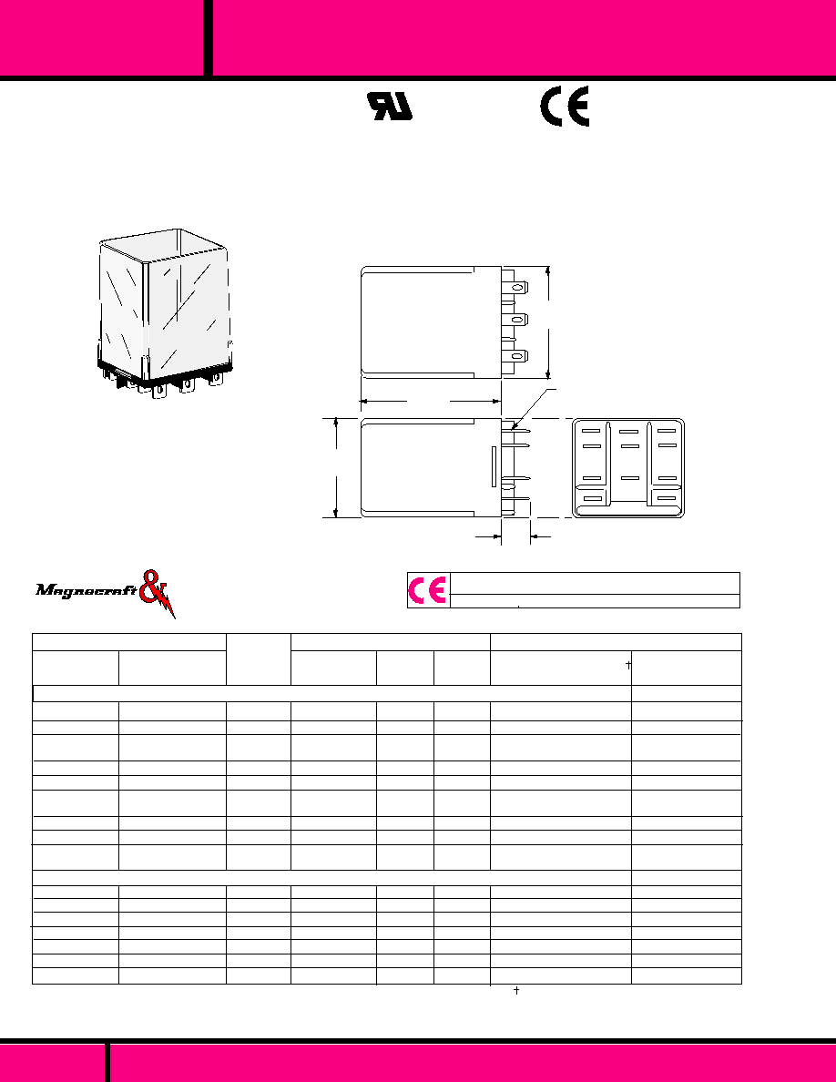
Standard Class 67 miniature industrial relays are designed
for applications requiringDPDT to 8PDT contacts where
space and weight are of prime importance.
Shatter resistant, see-thru plastic covers are utilized to
protect against dust, tampering and electrical shock.
The 67T models have Bifurcated Contacts and
are designed for low level switching applications.
SEE SECTION 10 FOR MATING SOCKETS.
CONTACT MATERIAL: SILVER GOLD OVERLAY
RATED 3 or 5 AMPS @ 32VDC/120VAC
DIELECTRIC STRENGTH
Contact to coil:
Across open contacts:
Coil to frame:
Contacts to frame:
Insulation resistance:
TEMPERATURE
Operating:
Storage:
MISCELLANEOUS
Solder-bath temperature:
Enclosure Material:
Operating Position:
Weight:
1500 V rms
500 V rms
1000 V rms
1500 V rms
1000 megohms @ 25�C & 50% R.H.
-55�C to + 70�C
-55�C to +105�C
+525�F (260�C) 10 seconds max.
Polycarbonate see thru plastic cover.
Any
0.77 to 1.4 oz. (22 to 40 grams)
SPECIFICATIONS CLASS 67
OPTIONS:
Other options such as other coil voltages, sensitivities, contact arrangements
and epoxy sealing are available on special order. Consult Factory for special
requirements.
The Class 67 Relays have combination
solder/plug-in terminals with a 3-48UNC
stud or printed circuit terminals.
8PDT
6PDT
4PDT
DPDT
4
3
2
1
WIRING DIAGRAM
Bottom View
80% of nominal voltage or less.
10% of nominal or more.
�
10% measured @ 25�C
2.2 watts
30�C per watt
105�C
Silver, Gold overlay
50 milliohms max. initial
2 pf, typ.
2 pf, typ.
30 pf, typ.
COIL
Pickup voltage:
Dropout voltage:
Coil resistance:
Maximum coil dissipation:
Coil Temperature rise:
Maximum coil temperature:
CONTACTS
Contact material:
Contact resistance:
CAPACITANCE
Between contacts:
Contact to coil:
Coil to frame:
UL RECOGNIZED
FILE NO. E52197
Load
Current
5.0A
5.0A
2.0A
1.0A
0.5A
0.1A
0.1A
50mA
30mA
1mA
10A
28 VDC
120VAC
28VDC/120VAC
28VDC/120VAC
28VDC/120VAC
28VDC/120VAC
6 VDC
6 VDC
6 VDC
6 VDC
10mVDC
Standard
adjustment
8
PDT
.018
.008
Measured at Nominal Voltage @ 25�C
4
PDT
.014
.008
POLES
OPERATE TIME
RELEASE TIME
DPDT
012
.008
6
PDT
.016
.008
CLASS 67 TYPICAL TIMING VALUES
Number of
Operations
Load
Voltage
5 X 10
4
5 X 10
4
1.5 X 10
6
1.2 X 10
7
-
5 X 10
7
-
5 X 10
7
-
-
5 X 10
7
TYPICAL CONTACT LIFE EXPECTANCY FOR SWITCHING
RESISTIVE LOADS @ 25�C
PAGE 13
WEBSITE: www.magnecraft.com EMAIL:info@magnecraft.com FAX ON DEMAND 1-800/891-2957, DOCUMENT 100
67
C L A S S
MINIATURE ENCLOSED INDUSTRIAL RELAY
.170
(4.3)
"A"
1.20 Max.
(30.3)
.200 Max.
(5.1)
3-48UNC-2A Thd.
.094
(2.3)
.098
(2.48)
Typ.
CONTACT
TERMINALS
.040
(1.0)
Typ.
.135
(3.42)
.053
(1.35)
COIL
TERMINALS
.735 Max.
(18.7)
.165
(4.19) Typ.
.400
(10.2)
.200
(5.1)
.450
(11.43)
.225
(5.7)
.210
(5.3)
.110
(2.7)
.320
(8.1)
.420
(10.6)
.530
(13. 4)
.630
(16.0)
.740
(18.8)
.060
�
.002 Dia.
(1.5)
�
(.05)
.550
(13..97)
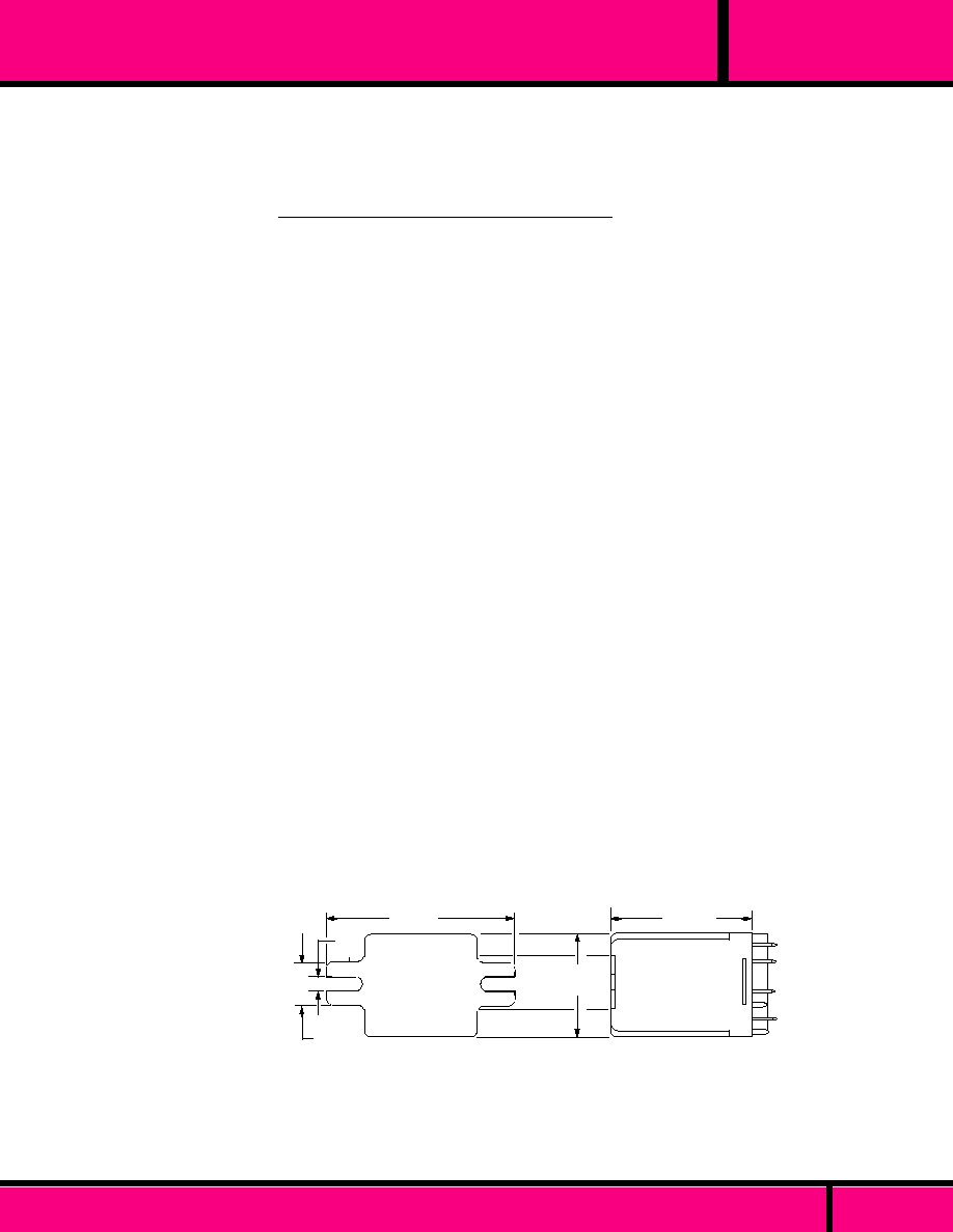
P.C RELAY PIN LAYOUT
SUGGESTED PRINTED CIRCUIT BOARD LAYOUT
FOR RELAYS WITH PRINTED CIRCUIT TERMINALS
OUTLINE DIMENSIONS
Dimensions shown in INCHES and (MILLIMETERS)
Elongated Hole .100 x .040 ( 2 x .1)
CONTACT
CONFIGU-
RATION
"A"
DIM.
.978
(24.8)
1.156
(29.4)
1.374
(34.9)
1.592
(40.4))
DPDT
4PDT
6PDT
8PDT
"A"
1.20 Max.
(30.3)
Tolerances
�
.010 Inches
DIMENSIONS
C L A S S
MINIATURE ENCLOSED INDUSTRIAL RELAY
.032
(0.80)
All Contact Terminals are .010 Thick.
All Coil Terminals are .018 Thick.
All Contact Terminals are .010 Thick
all coil terminals are .018 Thick.
PAGE 14
WEBSITE: www.magnecraft.com EMAIL:info@magnecraft.com FAX ON DEMAND 1-800/891-2957, DOCUMENT 100
67

5 AMPS
5 AMPS
5 AMPS
5 AMPS
5 AMPS
5 AMPS
5 AMPS
5 AMPS
5 AMPS
5 AMPS
5 AMPS
5 AMPS
5 AMPS
5 AMPS
5
12
24
48
115
5
12
24
48
115
12
24
12
24
1/2W
3/4W
1W
1W
1W
1/2W
3/4W
1W
1W
1W
1.5W
1.5W
2W
2W
DPDT
DPDT
DPDT
DPDT
DPDT
4PDT
4PDT
4PDT
4PDT
4PDT
6PDT
6PDT
8PDT
8PDT
3 AMPS
3 AMPS
3 AMPS
3 AMPS
3 AMPS
3 AMPS
3 AMPS
3 AMPS
52
185
700
2500
15,000
52
185
700
2500
15,000
90
430
72
350
W67RCSX-1
W67RCSX-2
W67RCSX-3
W67RCSX-4
W67RCSX-5
W67RCSX-6
W67RCSX-7
W67RCSX-8
W67RCSX-9
W67RCSX-10
W67RCSX-12
W67RCSX-13
W67RCSX-17
W67RCSX-18
W67TRCSX-2
W67TRCSX-3
W67TRCSX-7
W67TRCSX-8
W67TRCSX-12
W67TRCSX-13
W67TRCSX-17
W67TRCSX-18
CONTACT
RATING
NOMINAL
INPUT
VOLTAGE
NOMINAL
RESISTANCE
(OHMS)
NOMINAL
POWER
(WATTS)
STANDARD CONTACTS
DC OPERATED - SOLDER TERMINAL or PLUG-IN STYLE
PART NUMBERS
CROSS REFERENCE
TO
POTTER & BRUMFIELD
185
700
185
700
90
430
72
350
12
24
12
24
12
24
12
24
CONTACT
CONFIGU-
RATION
COIL
Measured @ 25�C
DC OPERATED - BIFURCATED CONTACTS - FOR LOW LEVEL SWITCHING APPLICATIONS
DPDT
DPDT
4PDT
4PDT
6PDT
6PDT
8PDT
8PDT
3/4W
1W
3/4W
1W
1.5W
1.5W
2W
2W
1.5VA
2.5VA
2.5VA
5 AMPS
5 AMPS
5 AMPS
DPDT
4PDT
6PDT
-
-
-
CONTACT
RATING
NOMINAL
INPUT
VOLTAGE
NOMINAL
POWER
(WATTS)
NOMINAL
RESISTANCE
(OHMS)
120 VAC
120 VAC
120 VAC
W67ARCSX-5
W67ARCSX-10
W67ARCSX-15
CLASS 67 - AC OPERATED RELAYS - SOLDER TERMINAL or PLUG-IN STYLE 50/60 Hz
COIL
Measured @ 25�C
STANDARD CONTACTS
PART NUMBERS
CROSS REFERENCE
TO
POTTER & BRUMFIELD
CONTACT
CONFIGU-
RATION
CONTACT
RATING
5 AMPS
5 AMPS
5 AMPS
5 AMPS
5 AMPS
5 AMPS
12 VDC
24 VDC
12 VDC
24 VDC
12 VDC
24 VDC
185
700
185
700
90
430
DPDT
DPDT
4PDT
4PDT
6PDT
6PDT
W67RPCX-2
W67RPCX-3
W67RPCX-7
W67RPCX-8
W67RPCX-12
W67RPCX-13
STANDARD CONTACTS
DC OPERATED - PRINTED CIRCUIT STYLE
PART NUMBERS
COIL
Measured @ 25�C
CROSS REFERENCE
TO
POTTER & BRUMFIELD
NOMINAL
INPUT
VOLTAGE
NOMINAL
RESISTANCE
(OHMS)
1W
1W
1W
1W
1.5W
1.5W
NOMINAL
POWER
(WATTS)
CONTACT
CONFIGU-
RATION
R10E1(X or Y)2-V28
R10E1(X or Y)2-V185
R10E1(X or Y)2-V700
R10E1(X or Y)2-V2.5K
R10E1(X or Y2-V15.0K
R10E1(X or Y)4-V28
R10E1(X or Y)4-V185
R10E1(X or Y)4-V700
R10E1(X or Y)4-V2.5K
R10E1(X or Y)4-V15.0K
R10E1(X or Y)6-V185
R10E1(X or Y)6-V700
R10E1(X or Y)8-V185
R10E1(X or Y)8-V700
R10E1(P or Z)2-V185
R10E1(P or Z)2-V700
R10E1(P or Z)4-V185
R10E1(P or Z)4-V700
R10E1(P or Z)6V185
R10E1(P or Z)6-V700
R10E1(P or Z)8-V185
R10E1(P or Z)8-V700
R10E1(X or Y)2-120V
R10E1(X or Y)4-120V
R10E1(X or Y)6-120V
R10E2(X or Y)2-V185
R10E2(X or Y)2-V700
R10E2(X or Y)4-V185
R10E2(X or Y)4-V700
R10E2(X or Y)6-V185
R10E2(X or Y)6-V700
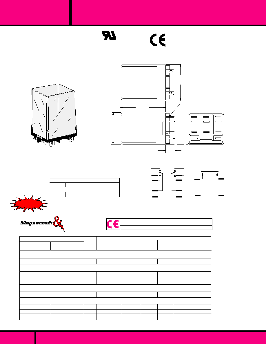
MINIATURE ENCLOSED INDUSTRIAL RELAY
C L A S S
Part numbers shown also available thru Stocking Distribution.
SEE SECTION 10 FOR MATING SOCKETS
BIFURCATED CONTACTS
( LOW LEVEL APPLICATIONS)
(5 AMP CROSS BAR)
STANDARD CONTACTS
WEBSITE: www.magnecraft.com EMAIL:info@magnecraft.com FAX ON DEMAND 1-800/891-2957, DOCUMENT 100
PAGE 15
67

WEBSITE: www.magnecraft.com - EMAIL:info@magnecraft.com - FAX ON DEMAND 1-800/891-2957 - DOCUMENT 100
PAGE 16
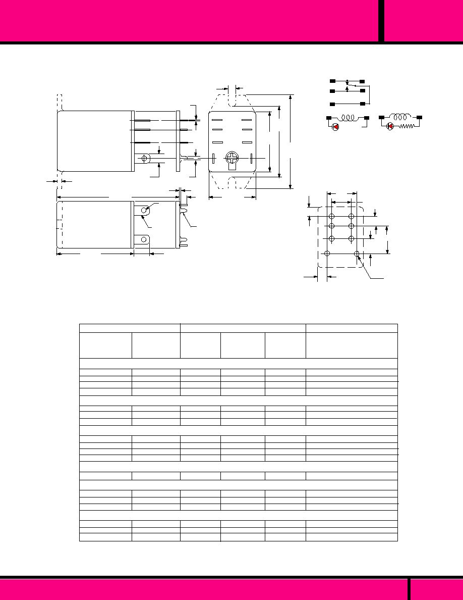
A314 & 250
CLASS
OCTAL STYLE 10 AMP GENERAL PURPOSE RELAY
FEATURES
Plug-in, 8 or 11 pin "Octal Style Base" with see thru plastic dust cover.
Standard SPDT, DPDT or 3PDT contact arrangements. Other contact
arrangements available on special order.
Dielectric Strength to 1500 Vrms.
8 or 11 pin octal style plug-in are standard and Interchangeable with
other general purpose relays of this type.
Available with combinations of Indicator lamps, push to test button and
Blow-out Magnets for DC switching applications.
MANUFACTURED UNDER QUALITY SYSTEM
ISO 9002 & QS 9000
SEE SECTION 10
FOR
MATING SOCKETS
Recognized Component mark for
Canada and the United States.
C US
UL Recognized
File No. E43641
DPDT
(+)
(-)
WIRING DIAGRAM
VIEWED FROM PIN END
SPDT
3
PDT
(+)
(-)
ALL INDICATOR LAMP STYLE RELAY HAVE AN ADDITIONAL LAMP CIRCUIT
INSTALLED ACROSS COIL. OBSERVE COIL POLARITY WHEN L.E.D. INDICA-
TOR IS INSTALLED ACROSS COIL (DC STYLES TYP.).
1.37
(34.79)
1.37
(34.79)
1
5
2
6
3
7
4
8
OUTLINE DIMENSIONS
Dimensions are shown in Inch and (Millimeter).
2.25 max.
(57.2)
Artwork marking side
2.81 max.
(71.4)
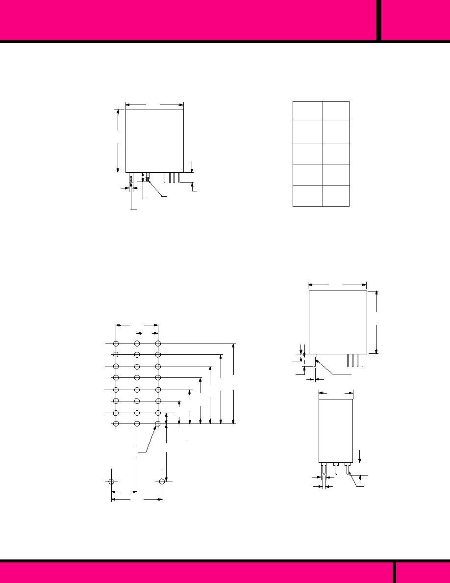
POLES
120 VAC
240 VAC
28 VDC
12 AMP
1/3 HP
12 AMP
1/3 HP
10 AMP
1/3 HP
12 AMP
1/2 HP
10 AMP
1/2 HP
10 AMP
1/2 HP
10 AMP
10 AMP
10 AMP
SPDT
DPDT
3PDT
CONTACT RATINGS TABLE

PAGE 17
A314 & 250
OCTAL STYLE 10 AMP GENERAL PURPOSE RELAY
SEE SECTION 10
FOR
MATING SOCKETS
80% of nominal voltage or less. for DC coils
85% of nominal voltage or less for AC coils.
10% of nominal voltage or more.
�
10 % measured @ 25 �C
125 milliwatts per pole
1.2 Watts for DC coils, 2 VA-2.75VA for AC coils
Capability of DC coils 3.0 Watts max.
Continuous
3/16" silver cadmium oxide, gold flashed Std.
Gold Diffused also available.
50 milliohms maximum initial resistance at rated current
12 V @ 100 Milliamps
15 mS or less at nominal voltage.
10 mS or less at nominal Voltage.
1500 V rms
500 V rms
1500 V rms
1500 V rms
1,000 Megohms min. @ 500 VDC
-45�C to +55�C (AC), -45�C to +70�C (DC)
-45�C to +105�C
5 G's,
20 G's
5 G's, 10 Hz to 55 Hz
Plastic dust cover with octal plug.
Molded plastic
Any
8 or 11 pin octal plug-in
3 1/2 ozs. 99.2 g approx.
COIL
Pull-in voltage:
Drop-out:
Coil resistance:
Minimum sensitivity:
Nominal power:
Maximum coil dissipation:
Duty:
CONTACTS
Contact material:
Contact resistance:
Minimum Load:
TIMING
Operate time:
Release time:
DIELECTRIC STRENGTH
Contacts to coil:
Across open contacts:
Pole to pole:
Contacts to frame:
Insulation resistance:
TEMPERATURE
Ambient Temperature (Operating):
Non operating storage:
SHOCK RESISTANCE
Operating:
Non operating:
VIBRATION RESISTANCE
Operating:
MISCELLANEOUS
Enclosure:
Insulation material:
Operating Position:
Terminals:
Weight:
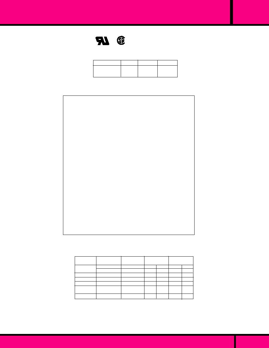
SPECIFICATIONS SERIES A314 & 250 RELAYS
CLASS A314 & 250
8 OR 11 PIN OCTAL PLUG-IN WITH SEE THRU DUST COVER.
Enclosure is a clear high impact plastic (polycarbonate)
dust cover that is screwed to the base to protect against dust,
damage and tampering.
C US
UL Recognized
File No. E43641
Recognized Component mark for
Canada and the United States.
WEBSITE: www.magnecraft.com - EMAIL:info@magnecraft.com - FAX ON DEMAND 1-800/891-2957 - DOCUMENT 100
CLASS

OCTAL STYLE 10 AMP GENERAL PURPOSE RELAY
A314XAX48P-24A
A314XAX48P-120A
A314XBX48P-24A
A314XBX48P-120A
A314XBX48P-240A
A314XCX48P-24A
A314XCX48P-120A
A314XCX48P-240A
A314XBX48PL-24A
A314XBX48PL-120A
A314XBX48PL-240A
A314XCX48PL-24A
A314XCX48PL-120A
A314XCX48PL-24OA
A314XAX48P-12D
A314XAX48P-24D
A314XBX48P-12D
A314XBX48P-24D
A314XCX48P-12D
A314XCX48P-24D
A314XBX48PL-24D
A314XCX48PL-24D
W250ACPX-3
W250ACPX-4
W250ACPX-8
W250ACPX-9
W250ACPX-10
W250ACPX-13
W250ACPX-14
W250ACPX-15
W250ANCPX-26
W250ANCPX-27
W250ANCPX-28
W250ANCPX-29
W250ANCPX-30
W250ANCPX-31
W250CPX-2
W250CPX-3
W250CPX-6
W250CPX-7
W250CPX-10
W250CPX-11
W250NCPX-20
W250NCPX-21
DC OPERATED
AC OPERATED WITH
INDICATOR LAMP
AC OPERATED
CONTACT
CONFIGU-
RATION
SPDT
SPDT
DPDT
DPDT
DPDT
3PDT
3PDT
3PDT
DPDT
DPDT
DPDT
3PDT
3PDT
3PDT
SPDT
SPDT
DPDT
DPDT
3PDT
3PDT
DPDT
3PDT
CROSS REFERENCE TO
Measured @ 25�C
COIL
24 VAC
120VAC
24 VAC
120VAC
240 VAC, 60 Hz
220 VAC, 50 Hz
24 VAC
120 VAC
240 VAC. 60 Hz
220 VAC, 50 Hz
24 VAC
120 VAC
240 VAC. 60 Hz
220 VAC, 50 Hz
24 VAC
120 VAC
240 VAC. 60 Hz
220 VAC, 50 Hz
12 VDC
24 VDC
12VDC
24 VDC
12 VDC
24 VDC
24 VDC
24 VDC
NOMINAL
INPUT
VOLTAGE
NOMINAL
RESIS-
TANCE
-
-
-
-
-
-
-
-
120
472
120
472
120
472
472
472
NOMINAL
POWER
2.0VA
2.0VA
2.75VA
2.75VA
2.75VA
2.75VA
2.75VA
2.75VA
2.0VA
2.0VA
2.75VA
2.0VA
2.0VA
2.75VA
1.2W
1.2W
1.2W
1.2W
1.2W
1.2W
1.2 W
1.2 W
KRPA5AG (or GF) -24
KRPA5AG (or GF) -120
KRPA11AG (or GF) -24
KRPA11AG (or GF) -120
KRPA11AG (or GF) -240
KRPA14AG (or GF) -24
KRPA14AG (or GF) -120
KRPA14AG (or GF) -240
KRPA11AN (or NF) -24
KRPA11AN (or NF) -120
KRPA11AN (or NF) -240
KRPA14AN (or NF) -24
KRPA14AN (or NF) -120
KRPA14AN (or NF) -240
KRPA5DG (or GF) -12
KRPA5DG (or GF) -24
KRPA11DG (or GF) -12
KRPA11DG (or GF) -24
KRPA14DG (or GF) -12
KRPA14DG (or GF) -24
KRPA11DN (or NF) -24
KRPA14DN (or NF) -24
POTTER &
BRUMFIELD
*
IDEC
-
-
RR2P-U-AC24V
RR2P-U-AC120V
RR2P-U-AC240V
RR3PA-U-AC24V
RR3PA-U-AC120V
RR3PA-U-AC240V
RR2P-UL-AC24V
RR2P-UL-AC120V
RR2P-UL-AC240V
RR3PA-UL-AC24V
RR3PA-UL-AC120V
RR3PA-UL-AC240V
-
-
RR2P-U-DC12V
RR2P-U-DC24V
RR3PA-U-DC12V
RR3PA-U-DC24V
RR2P-UL-DC24V
RR3PA-UL-DC24V
DC OPERATED WITH
INDICATOR LAMP
WEBSITE: www.magnecraft.com - EMAIL:info@magnecraft.com - FAX ON DEMAND 1-800/891-2957 - DOCUMENT 100
PAGE 18
-
-
DPDT
DPDT
DPDT
DPDT
DPDT
A314XBX48P69-24A
A314XBX48P69-120A
A314XBX48P69-12D
A314XBX48P69-24D
A314XBX48P69-110D
DC OPERATED WITH
BLOW-OUT MAGNET
-
-
120
472
10,000
8 PIN
8 PIN
8 PIN
8 PIN
8 PIN
2.0 VA
2.0 VA
1.2 W
1.2 W
1.2 W
24 VAC
120VAC
12 VDC
24 VDC
110 VDC
CONTACT
CONFIGU-
RATION
COIL
Measured @ 25�C
NOMINAL
INPUT
VOLTAGE
NOMINAL
POWER
NOMINAL
RESISTANCE
(OHMS)
NO. OF PINS
OCTAL
STYLE
AC OPERATED WITH
BLOW-OUT MAGNET
DUAL MARKED PART NUMBERS
SERIES A314
CLASS 250CP
Struthers-Dunn
PART NUMBERS SHOWN ALSO AVAILABLE THRU STOCKING DISTRIBUTION
*
F = GOLD FLASHED
POLES
120 VAC
240 VAC
30 VDC
12 AMP
1/3 HP
10 AMP
1/2 HP
10 AMP
DPDT
150 VDC
CONTACT RATINGS WITH
BLOW-OUT MAGNET
3 AMP
RELAYS FOR DC SWITCHING
RELAYS USING MAGNETIC BLOW-OUT MAGNETS ARE NOT AGENCY APPROVED.
PART
NUMBERS
A314 & 250
CLASS
RELAYS CAN BE ORDERED EITHER BY MAGNECRAFT OR STRUTHERS-DUNN PART NUMBERS LISTED BELOW
Struthers-Dunn

PAGE 19
WEBSITE: www.magnecraft.com - EMAIL:info@magnecraft.com - FAX ON DEMAND 1-800/891-2957 - DOCUMENT 100
1.50
(38.1)
1.31
(33.3)
0.218
(5.53)
1.87
(47.4)
0.28
(7.11)
1.93
(49.0)
MANUAL PUSH
B U T T O N
ACTUATOR (OPTIONAL)
0.187 Typ.
(4.74)
0.020 Typ.
(.508)
ORDERING CODE
Typical Type No.
Series
284 3 way terminals
10 Amp, 4 pole
Contact Arrangements
XDX (4PDT)
Construction Style
Open, with tapped 6-32 hole - NO CODE
Open, with 6-32 Stud - CODE S
Enclosed, 3 way terminals - CODE C
Options
10 Amp contacts Standard - NO CODE
Gold diffused contacts - CODE G
Indicator Lamp - CODE L
Manual Actuator - CODE M
Printed Circuit Terminals - CODE T
5 Amp contacts (Silver) - CODE Y
Coil Voltage
AC: 6, 12, 24, 48, 120, 240 (Add "A")
DC: 6, 12, 24, 48, 115, 125 (Add "D")
284 XDX C GLM -240A
Struthers-Dunn
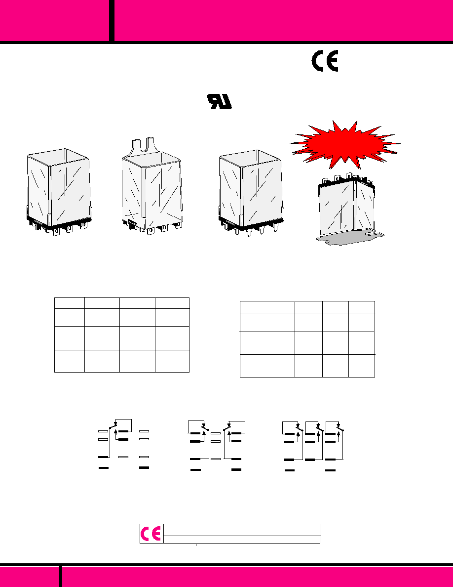
9
5
1
13
4
8
12
14
3
7
11
10
6
2
WIRING DIAGRAM
(VIEWED FROM TERMINAL END)
SEE NEXT PAGE FOR RATINGS & SPECIFICATIONS
OUTLINE DIMENSIONS
Dimensions shown are in INCHES and (millimeters)
SERIES
The series 284 relay is a extension of the Class 388/283
style relay except it provides for 4PDT contacts, any
one set of contacts capable of switching 10 Amps (total
load of 30 Amps at 120 VAC and 20 Amps at 240 VAC).
This relay has the 3 way terminal design for greater flexibility
in making connections. The 0.187 Spade terminals can be
soldered, plugged into sockets or connected using 3/16"
Q.C. Female connectors.
UL Recognized
File No. E13224
284
GENERAL PURPOSE 4 POLE 10 AMP PLUG-IN RELAY
CONTACT RATINGS
LOAD
Resistive Motor
Load 80% pF.
30VDC
120VAC
240VAC
10A
10A
1/3Hp
10A
1/2Hp
Maximum total load for 4 pole relay is 30 Amps @
120VAC, 20Amps @ 240VAC
UL Recognized
File No. E13224
GENERAL SPECIFICATIONS
NOTE: * For 220-250VDC coils use a 8,200
, 5 Watt resistor in series with
110-125 VDC relays
Nominal
Voltage
Resistance
Ohms
�
10%
Resistance
Ohms
�
10%
Current (MA)
6
12
24
48
120AC or
115-125DC
240AC*
3
12
48
-
870
4700
560
230
115
-
31
12
200
100
50
25
13-15
-*
3.4VA
3.4VA
3.4VA
3.4VA
3.4VA
3.4VA
1.2W
1.2W
1.2W
1.2W
1.2W
1.2W
AC
DC
AC
DC
AC
DC
30
120
480
1920
8200
-*
Power
Consumption
COIL
Pull-in Voltage:
Dropout Voltage:
Max. allowed voltage:
Coil Resistance:
CONTACTS
Contact Material:
TIMING
Operate Time:
Release Time:
DIELECTRIC STRENGTH
All Mutually Insulated Points:
Insulation Resistance:
TEMPERATURE
Temperature Rating:
LIFE EXPECTANCY
Mechanical:
Electrical:
MISCELLANEOUS
Enclosure:
Weight:
COIL SPECIFICATIONS @ 25�C
AC: 85%, DC: 75% of nominal voltage
measured at 25�C
10% of nominal voltage or more @ 25�C
110% of nominal voltage
�
10% Measured @ 25�C
Silver Cadmium Oxide.
15 mS Max. @ Nominal Voltage.
10 mS Max. @ Nominal Voltage.
500 V rms across open contacts
1500 V rms between current carrying
parts
1000 Megohms.min. @ 500 VDC
AC: -45�C to +50�C @ Rated Operation.
(+65�C for open style)
DC: -45�C to +70 �C
+85�C for open style)
10 Million Operations no load
100,000 Operations @ Rated Load.
Clear polycarbonate
5.0 oz. approx..
SERIES
284
GENERAL PURPOSE 4 POLE 10 AMP PLUG-IN RELAY
PAGE 20
WEBSITE: www.magnecraft.com - EMAIL:info@magnecraft.com - FAX ON DEMAND 1-800/891-2957 - DOCUMENT 100
PAGE 21
WEBSITE: www.magnecraft.com - EMAIL:info@magnecraft.com - FAX ON DEMAND 1-800/891-2957 - DOCUMENT 100
GENERAL SPECIFICATIONS
*
RELEVANT IEC CONTACT UTILIZATION CATEGORIES
AC-1, AC-3, DC-1, AC-15
(SEE SECTION 11 FOR RELEVANT UTILIZATION CATEGORIES.)
SEE SECTION 10 FOR MATING SOCKETS
The Class 388 & 283 general purpose relays are available in
a wide choice of AC or DC voltages with Indicator Lamp, Push to test
button and other options. Plug-in style relays have 3-way pierced
terminals. While spaced for standard plug-in Socket mounting.
The flat terminals (0.187 x 0.020) also accept quick connect
receptacles or direct soldering.
MANUFACTURED UNDER
QUALITY SYSTEM
ISO 9002 & QS 9000
COMPLIES WITH
REQUIREMENTS OF
IEC STANDARDS
947-4-1 AND 947-5-1
LOW VOLTAGE DIRECTIVE
IEC = INTERNATIONAL
ELECTROTECHNICAL COMMISSION
*
*
FLANGE MOUNT
NEW!
NEW!
NEW!
NEW!
NEW!
TOP FLANGE MOUNT
P.C. MOUNT
PLUG-IN
POLES
120 VAC
240 VAC
28 VDC
13 AMP
1/3 HP
13 AMP
1/3 HP
13 AMP
1/3 HP
13 AMP
1/2 HP
12 AMP
1/2 HP
11 AMP
1/2 HP
13 AMP
12 AMP
11 AMP
1 POLE
2 POLE
3 POLE
3PDT
DPDT
SPDT
POLES
125
18.0
30.0
250
20.0
28.0
MIN. OPERATE
mW
(SENSITIVITY)
OPERATE TIME
(Milliseconds
maximum.)
RELEASE TIME
(Milliseconds
Maximum.)
375
24.0
26.0
3
6
7
9
4
8
5
2
1
A
B
DPDT
Viewed from terminal end
WIRING DIAGRAMS
3
6
7
9
4
8
5
2
1
A
B
SPDT
3
6
7
9
4
8
5
2
1
A
B
3PDT
CONTACT RATINGS TABLE
TYPICAL OPERATING CHARACTERISTICS
(For DC Voltage types only).
C L A S S
Recognized Component mark for
Canada and the United States.
C US
UL Recognized
File No. E43641
388 & A283
SEE SECTION 10 FOR MATING SOCKETS
GENERAL SPECIFICATIONS
PAGE 22
WEBSITE: www.magnecraft.com - EMAIL:info@magnecraft.com - FAX ON DEMAND 1-800/891-2957 - DOCUMENT 100
C L A S S
SPECIFICATIONS CLASS 388 & 283 RELAYS
COIL
Pull-in voltage:
Dropout voltage:
Resistance:
Coil power
Insulation System:
Maximum coil dissipation:
Duty:
CONTACTS
Contact material:
Contact resistance:
DIELECTRIC STRENGTH
Contacts to coil:
Across open contacts:
Pole to pole
Contacts to frame:
Insulation resistance:
TEMPERATURE
Operating:
Storage
LIFE EXPECTANCY
Electrical:
Mechanical:
MISCELLANEOUS
Operating Position:
Insulation material:
Enclosure:
Terminals:
Weight:
80% of nominal voltage or less. for DC coils.
85% of nominal voltage or less for AC coils.
10% of nominal voltage or more.
�
10 % Measured at 25�C
1.2 Watts for DC coils, 2 VA to 2.75 VA for AC coils
Class "B" (130�C per UL std. 1446)
Capability of DC coils 3.0 Watts max.
Continuous
3/16" silver cadmium oxide, gold flashed.
50 Milliohms maximum initial resistance
at rated current
2000 V rms
500 V rms
2000 V rms
2000 V rms
1000 Megohms @ 500 VDC
-30�C to +50�C (AC), -30�C to +65�C (DC)
-30�C to 100�C
100,000 Operations @ rated AC load
5,000,000 Operations @ No load
Any
Molded plastic
Clear Polycarbonate dust cover
3/16" solder/plug-in, Printed Circuit terminals
other terminals available: .205 x .032, .250 x .032
on special order. Consult Factory.
3.1 oz.. (88 g approx. with cover).
OPTIONAL
TOP FLANGE COVER
IS AVAILABLE ON
SPECIAL ORDER.
CONSULT FACTORY.
1.90Max.
(48.4)
1.40Max.
(35.5)
2.53
(64.29)
1.41
(35.8)
.500
(12.7)
388 & A283
C L A S S
CLASS 388 & 283 RELAY
13 AMP CONTACT RATING
MANUFACTURED UNDER
QUALITY SYSTEM
ISO 9002 & QS 9000
.28 Typ.
(7.1)
1
2
3
4
5
6
.187 x .020
(4.76 x 0.51)
QC Terminals Typical
B
A
8
7
9
1.90Max.
(48.4)
1.53 Max.
(38.8)
Dimensions shown are in "INCH" and (Millimeter)
OUTLINE DIMENSIONS
1.40Max.
(35.5)
C US
UL Recognized
File No. E43641
Recognized Component mark for
Canada and the United States.
COMPLIES WITH
REQUIREMENTS OF
IEC STANDARDS
947-4-1 AND 947-5-1
LOW VOLTAGE DIRECTIVE
IEC = INTERNATIONAL
ELECTROTECHNICAL COMMISSION
*
*
OPTIONAL INDICATOR LAMP AND PUSH TO TEST
BUTTON AVAILABLE ON SPECIAL ORDER.
SEE SECTION 10 FOR MATING SOCKETS
W388ACPX-3
W388ACPX-4
W388ACPX-5
W388ACPX-8
W388ACPX-9
W388ACPX-10
W388ACPX-13
W388ACPX-14
W388ACPX-15
W388CPX-2
W388CPX-3
W388CPX-6
W388CPX-7
W388CPX-8
W388CPX-10
W388CPX-11
A283XAXC-24A
A283XAXC-120A
A283XAXC-240A
A283XBXC-24A
A283XBXC-120A
A283XBXC-240A
A283XCXC-24A
A283XCXC-120A
A283XCXC-240A
A283XAXC-12D
A283XAXC-24D
A283XBXC-12D
A283XBXC-24D
A283XBXC-110D
A283XCXC-12D
A283XCXC-24D
SPDT
SPDT
SPDT
DPDT
DPDT
DPDT
3PDT
3PDT
3PDT
SPDT
SPDT
DPDT
DPDT
DPDT
3PDT
3PDT
CONTACT
CONFIGU-
RATION
AC OPERATED
NOMINAL
INPUT
VOLTAGE
24 VAC
120VAC
240 VAC, 60 Hz
220 VAC, 50 Hz
24 VAC
120 VAC
240 VAC. 60 Hz
220 VAC, 50 Hz
24 VAC
120 VAC
240VAC, 60Hz
220 VAC, 50Hz
12 VDC
24 VDC
12 VDC
24 VDC
110VDC
12 VDC
24 VDC
Measured @ 25�C
COIL
-
-
-
-
-
-
-
-
-
-
120
472
120
472
10,000
120
472
2.0VA
2.0VA
2.0VA
2.0VA
2.0VA
2.0VA
2.75VA
2.75VA
2.75VA
2.75VA
1.2W
1.2W
1.2W
1.2W
1.2W
1.2W
1.2W
NOMINAL
POWER
NOMINAL
RESIS-
TANCE
CROSS REFERENCE TO
KUP5A15 (or F) - 24
KUP5A15 (or F) - 120
KUP5A15 (or F) - 240
KUP11A15 (or F) - 24
KUP11A15 (or F) - 120
KUP11A15 (or F) - 240
KUP14A15 (or F) - 24
KUP14A15 (or F) - 120
KUP14A15 (or F) - 240
KUP5D15 (or F) - 12
KUP5D15 (or F) - 24
KUP11D15 (or F) - 12
KUP11D15 (or F) - 24
KUP11D15 (or F) - 110
KUP14D15 (or F) - 12
KUP14D15 (or F) - 24
POTTER & BRUMFIELD
DUAL MARKED PART NUMBERS
CLASS 388CP
F = GOLD FLASHED
IDEC
DC OPERATED
Struthers-Dunn
CLASS A283
Struthers-Dunn
RELAYS CAN BE ORDERED EITHER BY MAGNECRAFT OR STRUTHERS-DUNN PART NUMBERS LISTED BELOW
*
RELEVANT IEC CONTACT UTILIZATION CATEGORIES
AC-1, AC-3, DC-1, AC-15
(SEE SECTION 11 FOR RELEVANT UTILIZATION CATEGORIES.)
PART NUMBERS SHOWN ALSO AVAILABLE THRU STOCKING DISTRIBUTION.
SEE GENERAL SPECIFICATIONS & WIRING DIAGRAMS FOR CLASS 388 & A283 RELAYS.
RR1BA-U-AC24V
RR1BA-U-AC120V
RR1BA-U-AC240V
RR2BA-U-AC24V
RR2BA-U-AC120V
RR2BA-U-AC240V
RR3B-U-AC24V
RR3B-U-AC120V
RR3B-U-AC240V
RR1BA-U-DC12V
RR1BA-U-DC24V
RR2BA-U-DC12V
RR2BA-U-DC24V
RR2B-U-DC110V
RR3B-U-DC12V
RR3B-U-DC24V
388 & A283
SQUARE BASE RELAY, SOLDER/PLUG-IN
PAGE 23
WEBSITE: www.magnecraft.com - EMAIL:info@magnecraft.com - FAX ON DEMAND 1-800/891-2957 - DOCUMENT 100

FLANGE MOUNT RELAY
13 AMP CONTACT RATING
.187 Q.C. /SOLDER TERMINALS
TOP FLANGE COVER AVAILABLE ON
SPECIAL ORDER. CONSULT FACTORY
OPTIONAL INDICATOR LAMP AND PUSH TO TEST
BUTTON AVAILABLE ON SPECIAL ORDER.
MANUFACTURED UNDER
QUALITY SYSTEM
ISO 9002 & QS 9000
C US
UL Recognized
File No. E43641
Recognized Component mark for
Canada and the United States.
COMPLIES WITH
REQUIREMENTS OF
IEC STANDARDS
947-4-1 AND 947-5-1
LOW VOLTAGE DIRECTIVE
IEC = INTERNATIONAL
ELECTROTECHNICAL COMMISSION
*
*
.187
(4.76)
1.53 Max.
(38.8)
.625 Typ.
(15.8)
2.90Max.
(73.8)
2.50
(63.5)
.187 x .020
(4.76 x 0.51)
QC Terminals Typical
4
1
2
3
6
5
A
B
8
9
7
.28 Typ.
(7.1)
1.40Max.
(35.5)
1.90Max.
(48.4)
.156
(3.9)
A283XAXC1-120A
A283XAXC1-240A
A283XBXC1-120A
A283XBXC1-240A
A283XCXC1-120A
A283XCXC1-240A
A283XAXC1-12D
A283XAXC1-24D
A283XBXC1-12D
A283XBXC1-24D
A283XCXC1-24D
W388ACQX-4
W388ACQX-5
W388ACQX-9
W388ACQX-10
W388ACQX-14
W388ACQX-15
W388CQX-2
W388CQX-3
W388CQX-6
W388CQX-7
W388CQX-11
-
-
-
-
-
120
472
120
472
472
SPDT
SPDT
DPDT
DPDT
3PDT
3PDT
SPDT
SPDT
DPDT
DPDT
3PDT
COIL
Measured @ 25�C
NOMINAL
INPUT
VOLTAGE
NOMINAL
RESIS-
TANCE
(OHMS)
2.0VA
2.0VA
2.0VA
2.0VA
2.75VA
2.75VA
1.2W
1.2W
1.2W
1.2W
1.2W
NOMINAL
POWER
120 VAC
240 VAC, 60Hz
220 VAC, 50 Hz
120 VAC
240 VAC. 60 Hz
220 VAC, 50 Hz
120 VAC
240VAC, 60Hz
220 VAC, 50Hz
12 VDC
24 VDC
12 VDC
24 VDC
24 VDC
CONTACT
CONFIGURATION
KUP5A55 (or F) - 120
KUP5A55 (or F) - 240
KUP11A55 (or F) - 120
KUP11A55 (or F) - 240
KUP14A55 (or F) - 120
KUP14A55 (or F) - 240
KUP5D55 (or F) - 12
KUP5D55 (or F) - 24
KUP11D55 (or F) - 12
KUP11D55 (or F) - 24
KUP14D55 (or F) - 24
RR1BA-US-AC120V
RR1BA-US-AC240V
RR2BA-US-AC120V
RR2BA-US-AC240V
RR3B-US-AC120V
RR3B-US-AC240V
RR1BA-US-DC12V
RR1BA-US-DC24V
RR2BA-US-DC12V
RR2BA-US-DC24V
RR3B-US-DC24V
POTTER &
BRUMFIELD
IDEC
AC OPERATED
DC OPERATED
CROSS REFERENCE TO
F = GOLD FLASHED
DUAL MARKED PART NUMBERS
RELAYS CAN BE ORDERED EITHER BY MAGNECRAFT OR STRUTHERS-DUNN PART NUMBERS LISTED BELOW
W388CQ
A283
Struthers-Dunn
Struthers-Dunn
*
RELEVANT IEC CONTACT UTILIZATION CATEGORIES
AC-1, AC-3, DC-1, AC-15
(SEE SECTION 11 FOR RELEVANT UTILIZATION CATEGORIES.)
PART NUMBERS SHOWN ALSO AVAILABLE THRU STOCKING DISTRIBUTION.
SEE GENERAL SPECIFICATIONS & WIRING DIAGRAMS FOR CLASS 388 & A283 RELAYS.
388 & A283
C L A S S
SQUARE BASE FLANGE MOUNT RELAYS
PAGE 24
WEBSITE: www.magnecraft.com - EMAIL:info@magnecraft.com - FAX ON DEMAND 1-800/891-2957 - DOCUMENT 100
CLASS 388B & 388DB
SQUARE BASE PLUG-IN STYLE
WITH MAGNETIC BLOWOUT FOR
DC SWITCHING.
RATED 3 & 10 AMPS AT 150 VDC
TOP FLANGE COVER AVAILABLE ON
SPECIAL ORDER. CONSULT FACTORY
MANUFACTURED UNDER
QUALITY SYSTEM
ISO 9002 & QS 9000
C US
UL Recognized
File No. E43641
& E13224
Recognized Component mark for
Canada and the United States.
PAGE 25
WEBSITE: www.magnecraft.com - EMAIL:info@magnecraft.com - FAX ON DEMAND 1-800/891-2957 - DOCUMENT 100
C L A S S
388B & A283
SQUARE BASE RELAYS WITH MAGNETIC BLOWOUT
WIRING
DIAG.
FIG.
120 VAC
12 VDC
24VDC
110 VDC
120 VAC
12 VDC
24 VDC
110 VDC
CONTACT
CONFIGU-
RATION
W388ABCPX-5
W388BCPX-2
W388BCPX-3
W388BCPX-5
W388ADBCPX-5
W388DBCPX-2
W388DBCPX-3
W388DBCPX-5
DPDT
DPDT
DPDT
DPDT
SPST-NO (DM)
SPST-NO (DM)
SPST-NO (DM)
SPST-NO (DM)
"A"
"A"
"A"
"A"
'B'
'B'
'B'
'B'
A283XBX69C-120A
A283XBX69C-12D
A283XBX69C-24D
A283XBX69C-110D
A283HXX69C-120A
A283HXX69C-12D
A283HXX69C-24D
A283HXX69C-110D
-
120
472
10,000
-
120
472
10,000
2.0VA
1.2W
1.2W
1.2W
2.OVA
1.2W
1.2W
1.2W
NOMINAL
INPUT
VOLTAGE
NOMINAL
RESISTANCE
(OHMS)
NOMINAL
POWER
CROSS REFERENCE
T O
P O T T E R / B R U M F I E L D
KUEP-11A15-120
KUEP-11D15-12
KUEP-11D15-24
KUEP-11D15-110
KUEP-3A15-120
KUEP-3D15-12
KUEP-3D15-24
KUEP-3D15-110
DC OPERATED WITH
BLOWOUT MAGNET
(3 AMP CONTACTS)
AC OPERATED WITH
BLOWOUT MAGNET
(10 AMP CONTACTS)
DC OPERATED WITH
BLOWOUT MAGNET
(10 AMP CONTACTS)
COIL Measured @ 25�C
RELAYS CAN BE ORDERED EITHER BY MAGNECRAFT OR STRUTHERS-DUNN PART NUMBERS LISTED BELOW
DUAL MARKED PART NUMBERS
A283
Struthers-Dunn
W388B
AC OPERATED WITH
BLOWOUT MAGNET
(3 AMP CONTACTS)
PART NUMBERS SHOWN ALSO AVAILABLE THRU STOCKING DISTRIBUTION.
SEE SECTION 10 FOR MATING SOCKETS
3
6
7
9
4
1
A
B
6
4
A
B
DPDT
FIG. "A"
SPST-NO-DM
FIG. "B"
Viewed from terminal end
WIRING DIAGRAM
*
RELEVANT IEC CONTACT UTILIZATION CATEGORIES
AC-1, AC-3, DC-1, AC-15
(SEE SECTION 11 FOR RELEVANT UTILIZATION CATEGORIES.)
COMPLIES WITH
REQUIREMENTS OF
IEC STANDARDS
947-4-1 AND 947-5-1
LOW VOLTAGE DIRECTIVE
IEC = INTERNATIONAL
ELECTROTECHNICAL COMMISSION
*
*
1
2
3
4
5
6
.28 Typ.
(7.1)
1.40Max.
(35.5)
.187 x .020
(4.76 x 0.51)
QC Terminals Typical
B
A
8
7
9
1.90Max.
(48.4)
1.53 Max.
(38.8)
Dimensions shown are in "INCHES" and (Millimeters)
OUTLINE DIMENSIONS
Struthers-Dunn
The Class 388B/388DB style relays have the same load
specifications as the 388/283 enclosed plug-in style relays
plus the additional load ratings charted on this page.
See 388& A283 General specifications.
3 AMPS
10 AMPS
DPDT FIG. "A"
SPDT-N.O. -DM FIG. "B"
150VDC
RESISTIVE
RESISTIVE
150VDC
DC LOAD RATINGS
DPST-NO & DPST-NC CONTACT VERSIONS
WITH BLOWOUT MAGNETS NOW UL APPROVED
@ 5 AMPS, 150 VDC.
ALSO
AVAILABLE
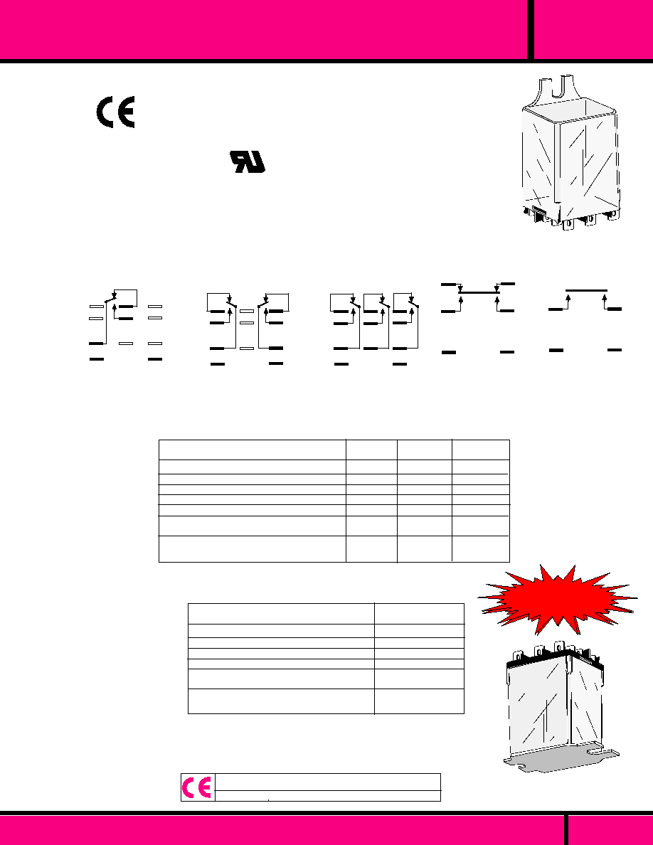
WEBSITE: www.magnecraft.com - EMAIL:info@magnecraft.com - FAX ON DEMAND 1-800/891-2957 - DOCUMENT 100
GENERAL SPECIFICATIONS
389
C L A S S
*
RELEVANT IEC CONTACT UTILIZATION CATEGORIES
AC-1, AC-3, DC-1, AC-15
(SEE SECTION 11 FOR RELEVANT UTILIZATION CATEGORIES.)
*
*
COMPLIES WITH
REQUIREMENTS OF
IEC STANDARDS
947-4-1 AND 947-5-1
LOW VOLTAGE DIRECTIVE
IEC = INTERNATIONAL
ELECTROTECHNICAL COMMISSION
C US
UL Recognized
File No. E43641
Recognized Component mark for
Canada and the United States.
3
6
7
9
4
8
5
2
1
A
B
3PDT
3
6
7
9
4
8
5
2
1
A
B
DPDT
3
6
7
9
4
8
5
2
1
A
B
SPDT
6
4
A
B
SPDT-NC-NO-
(DB-DM)
3
1
6
4
A
B
SPST-NO-(DM)
Viewed from terminal end
WIRING DIAGRAMS
POINTS WHERE VOLTAGE IS APPLIED
ACROSS OPEN CONTACTS
POLE- TO- ADJACENT POLE
COIL TO FRAME
COIL TO CONTACTS
CONTACT TO FRAME
CONTACTS TO METAL
MOUNTING PLATE ( COVER INSTALLED)
COIL TO METAL MOUNTING PLATE
(COVER INSTALLED)
SPDT
DPDT
3PDT
1000
1600
1600
1600
1600
1600
2200
CLASS 389 DIELECTRIC WITHSTANDING VOLTAGES (VRMS)
1, 2 & 3 POLE STYLE RELAYS
POINTS WHERE VOLTAGE IS APPLIED
ACROSS OPEN CONTACTS
COIL TO FRAME
COIL TO CONTACTS
CONTACT TO FRAME
CONTACTS TO METAL
MOUNTING PLATE ( COVER INSTALLED)
COIL TO METAL MOUNTING PLATE
(COVER INSTALLED)
ENCLOSED STYLE
1500
1600
2200
1600
2200
2200
CLASS 389D DIELECTRIC WITHSTANDING VOLTAGES VRMS)
SPDT-NC-NO (DB-DM), SPST-NO - (DM)
1000
2200
1600
2200
1600
2200
2200
1000
-
1600
2200
1600
2200
2200
The Class 389 relays are high quality general purpose relays, designed to switch
larger loads without increasing overall size. One, two and three pole relays are
available with a choice of Indicator lamp, Push to test button and various contact
combinations. Double make and double break styles are available only with a one
pole style but is capable of switching larger loads and are especially well suited for
switching motor loads. These relays are available in the 30 Amp contact range.
MANUFACTURED UNDER
QUALITY SYSTEM
ISO 9002 & QS 9000
NEW!
NEW!
NEW!
NEW!
NEW!
TOP FLANGE MOUNT
FLANGE MOUNT
PAGE 26

GENERAL SPECIFICATIONS
COIL
Pull-in voltage:
Dropout voltage:
Coil resistance:
Nominal power:
Maximum coil dissipation:
Duty:
Insulation System:
CONTACTS
Contact material:
Contact Gap:
Contact resistance:
TIMING
Operate time, (excluding bounce):
Release time, (excluding bounce):
DIELECTRIC STRENGTH
Insulation resistance:
TEMPERATURE
Operating:
Storage:
LIFE
Electrical:
Mechanical:
MISCELLANEOUS
Enclosure:
Operating Position:
Insulation material:
Terminals:
Weight:
80% of nominal voltage or less. for DC coils.
85% of nominal voltage or less for AC coils.
10% of nominal voltage or more.
�
10 % Measured at 25�C
1.44 Watts for DC coils, 2VA to 3.5VA for AC coils
Capability of DC coils 2.5 Watts max.
Continuous
Class "B" coil system. (130�C per UL std. 1446).
1/4" silver cadmium oxide, gold flashed.
.015 min. is standard.
50 Milliohms maximum initial resistance at rated current
20 milliseconds max.at nominal voltage.
20 milliseconds max.at nominal voltage.
1,000 Megohms min. @ 500 VDC
-30�C to +50�C (AC), -30�C to +65�C (DC)
-30�C to 100�C
100,000 at rated load.
5 Million Operations no load
Clear Polycarbonate dust cover
Any
Molded plastic
1/4" x .032 Q.C. Terminals suitable for solder or Q.C. connectors,
also available with Printed Circuit terminals. (.090 x .032)
3.3 oz.. (94 g approx. with cover).
389
C L A S S
PAGE 27
WEBSITE: www.magnecraft.com - EMAIL:info@magnecraft.com - FAX ON DEMAND 1-800/891-2957 - DOCUMENT 100
OPTIONAL
TOP FLANGE COVER
IS AVAILABLE ON
SPECIAL ORDER.
CONSULT FACTORY.
1.90Max.
(48.4)
1.40Max.
(35.5)
2.53
(64.29)
1.41
(35.8)
.500
(12.7)
SPECIFICATIONS CLASS 389 RELAYS
The 300 series was developed as a 600 Volt relay that would accept 1/4" booted
terminals. Its extra spacing permits contact gaps to 2 millimeters when required.
This increases dielectric strength across open contacts to 2500 Volts RMS.
Consult factory for details or additional information.
ALSO
AVAILABLE
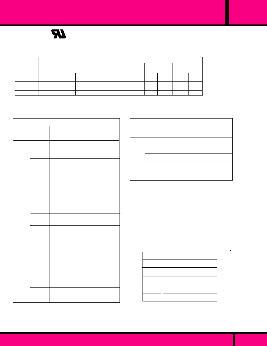
GENERAL CONTACT RATINGS
C US
UL Recognized
File No. E43641
Recognized Component mark for
Canada and the United States.
A 6 0 0
B 3 0 0
B 6 0 0
1 0
5
5
1, 2 & 3 POLE NEMA PILOT DUTY CONTACT RATINGS
MAXIMUM
V O L T - A M P E R E S
720
360
360
BREAK
MAKE
7200
3600
3600
600 VOLTS
50/60Hz
BREAK
MAKE
BREAK
1.50
0.75
MAKE
1 5
0.75
480 VOLTS
50/60Hz
BREAK
MAKE
3.00
1.50
1.50
3 0
1 5
1 5
240 VOLTS
50/60Hz
120 VOLTS
50/60Hz
BREAK
6.00
3.00
3.00
MAKE
6 0
3 0
3 0
THERMAL
CONTINUOUS
TEST CURRENT
AMPERES
NEMA
CONTACT
CODE
DESIGNATION
1 2
6
1.20
0.06
MAXIMUM CURRENT, AMPERES
NO. OF
P O L E S
C U R R E N T
O R
H O R S E -
P O W E R
13A
20A
25A
5A
1HP
1-1/2HP
1HP
660VA
915VA
960VA
765VA
B600
DC
DC (NO)
DC
50/60 Hz
50/60 Hz
50/60 Hz
50/60 Hz
50/60 Hz
50/60Hz
50/60 Hz
50/60 Hz
50/60Hz
RESISTIVE
RESISTIVE
RESISTIVE
RESISTIVE
RESISTIVE
RESISTIVE
MOTOR
MOTOR
MOTOR
PILOT DUTY
PILOT DUTY
PILOT DUTY
28
28
15
150
250
300
120/208/240
240
120
120/240
208
13A
15A
20A
20A
**15A
*10A
1/2HP
1HP
3/4HP
470VA
445VA
B300
ENCLOSED STYLE 1, 2 and 3 POLE
RESISTIVE
RESISTIVE
RESISTIVE
RESISTIVE
MOTOR
MOTOR
MOTOR
PILOT DUTY
PILOT DUTY
PILOT DUTY
PILOT DUTY
PILOT DUTY
28
15
300
600
120
208/240
480/600
120
208
240
480/600
13A
20A
25A
5A
1HP
1-1/2HP
1HP
660VA
915VA
960VA
765VA
B600
28
15
300
600
120
208/240
480/600
120
208
240
460/600
DC
DC
50/60 Hz
50/60 Hz
50/60 Hz
50/60 Hz
50/60 Hz
50/60 Hz
50/60 Hz
50/60 Hz
50/60 Hz
50/60Hz
3
P
O
L
E
2
P
O
L
E
1
P
O
L
E
DC
DC
50/60 Hz
50/60 Hz
50/60 Hz
50/60 Hz
50/60 Hz
50/60 Hz
50/60 Hz
50/60 Hz
50/60 Hz
50/60Hz
L O A D
V O L T A G E
F R E Q U E N C Y
L O A D
V O L T A G E
T Y P E
O F
L O A D
CLASS 389 LOAD RATINGS
RESISTIVE
RESISTIVE
RESISTIVE
RESISTIVE
MOTOR
MOTOR
MOTOR
PILOT DUTY
PILOT DUTY
PILOT DUTY
PILOT DUTY
PILOT DUTY
1
P
O
L
E
ENCLOSED STYLE
NO. OF
P O L E S
30A
30A
10A
1HP
1-1/2HP
765VA
915VA
960VA
A600
T Y P E
O F
L O A D
LOAD
VOLTAGE
FREQUENCY
DC
50/60 Hz
50/60 Hz
50/60 Hz
50/60 Hz
50/60 Hz
50/60 Hz
50/60 Hz
50/60 Hz
L O A D
V O L T A G E
28
300
600
120
200 thru 600
120
208
240,480,600
C U R R E N T
O R
H O R S E -
P O W E R
RESISTIVE
RESISTIVE
RESISTIVE
MOTOR
MOTOR
PILOT DUTY
PILOT DUTY
PILOT DUTY
PILOT DUTY
CLASS 389D LOAD RATINGS
Not CSA rated with ** are UL Appliance rated.
All other ratings not so marked are industrial rated
* CSA rating only, not UL
389
C L A S S
PAGE 28
WEBSITE: www.magnecraft.com - EMAIL:info@magnecraft.com - FAX ON DEMAND 1-800/891-2957 - DOCUMENT 100
NO. OF
P O L E S
1 POLE
2 POLE
3 POLE
1 POLE
ENCLOSED STYLE
20 AMPS, 277VAC, 50/60Hz
20 AMPS, 277VAC, 50/60Hz
20 AMPS,150VAC, 50/60Hz
6-2/3 AMPS, 277VAC, 50/60Hz
25 AMPS, 277VAC, 50/60Hz
DOUBLE BREAK DOUBLE MAKE (1 FORM "X" & "Z")
CLASS 389 BALLAST LOAD RATINGS

C L A S S
389
SQUARE BASE, 30 AMP POWER RELAY
CLASS 389D
1/4" Q.C. MALE TAB TERMINALS
FOR USE WITH FEMALE QUICK
CONNECT TERMINALS OR
SUITABLE FOR SOLDERING.
TOP FLANGE COVER AVAILABLE ON
SPECIAL ORDER. CONSULT FACTORY
OPTIONAL INDICATOR LAMP AND PUSH TO TEST
BUTTON AVAILABLE ON SPECIAL ORDER.
MANUFACTURED UNDER
QUALITY SYSTEM
ISO 9002 & QS 9000
.250 x .032
(6.35 x .891)
QC Terminals Typical
4
1
2
3
6
5
A
B
8
9
7
1.53 Max.
(38.8)
1.90Max.
(48.4)
1.40Max.
(35.5)
.28 Typ.
(7.1)
.625 Typ.
(15.8)
.156
(3.9)
2.90Max.
(73.8)
2.50
(63.5)
.187
(4.76)
FLANGE COVER
OUTLINE DIMENSIONS
Dimensions shown in Inches and (millimeters).
*
*
COMPLIES WITH
REQUIREMENTS OF
IEC STANDARDS
947-4-1 AND 947-5-1
LOW VOLTAGE DIRECTIVE
IEC = INTERNATIONAL
ELECTROTECHNICAL COMMISSION
UL Recognized
File No. E43641
Recognized Component mark for
Canada and the United States.
C US
COIL
CONTACT
CONFIGU-
RATION
SPST-NO-(DM)
SPST-NO-(DM)
S P D T - N O - N C
(DM-DB)
S P D T - N O - N C
(DM-DB)
SPST-NO-(DM)
SPST-NO-(DM)
S P D T - N O - N C
(DM-DB)
S P D T - N O - N C
(DM-DB)
30 AMP
30 AMP
30 AMP
30 AMP
30 AMP
30 AMP
30 AMP
30 AMP
120 VAC
240VAC, 60Hz
220 VAC, 50Hz
24 VAC
120VAC
12 VDC
24 VDC
12 VDC
24VDC
-
-
-
-
100
400
100
400
2.75VA
2.75VA
3.75VA
3.75VA
1.44W
1.44W
1.44W
1.44W
W389ADCX-4
W389ADCX-5
W389ADZCX-3
W389ADZCX-4
W389DCX-2
W389DCX-3
W389DZCX-2
W389DZCX-3
DC OPERATED
AC OPERATED
Measured @ 25�C
CONTACT
RATING
NOMINAL
RESISTANCE
(OHMS)
NOMINAL
POWER
CROSS REFERENCE
TO
POTTER & BRUMFIELD
KUMP3A5G-120
KUMP3A5G-240
KUMP6A5G-24
KUMP6A5G-120
KUMP3D5G-12
KUMP3D5G-24
KUMP6D5G-12
KUMP6D5G-24
NOMINAL
INPUT
VOLTAGE
EXCEPTION TO CROSS REFERENCE:
MAGNECRAFT RELAYS ARE RATED AT 3O AMPS , P&B 15 AMPS
PART NUMBERS SHOWN ALSO AVAILABLE THRU STOCKING DISTRIBUTION.
PART
NUMBERS
*
RELEVANT IEC CONTACT UTILIZATION CATEGORIES
AC-1, AC-3, DC-1, AC-15
(SEE SECTION 11 FOR RELEVANT UTILIZATION CATEGORIES.)
SEE CLASS 389 GENERAL SPECIFICATIONS AND WIRING DIAGRAMS.
WEBSITE: www.magnecraft.com - EMAIL:info@magnecraft.com - FAX ON DEMAND 1-800/891-2957 - DOCUMENT 100
PAGE 29

C L A S S
389
SQUARE BASE, 25 AMP POWER RELAY
CLASS 389 RELAY
1/4" MALE TAB TERMINALS FOR
USE WITH FEMALE QUICK CONNECT
TERMINALS OR SUITABLE FOR SOLDERING
TOP FLANGE COVER AVAILABLE ON
SPECIAL ORDER. CONSULT FACTORY
OPTIONAL INDICATOR LAMP AND PUSH TO TEST
BUTTON AVAILABLE ON SPECIAL ORDER.
MANUFACTURED UNDER
QUALITY SYSTEM
ISO 9002 & QS 9000
C US
UL Recognized
File No. E43641
Recognized Component mark for
Canada and the United States.
*
*
COMPLIES WITH
REQUIREMENTS OF
IEC STANDARDS
947-4-1 AND 947-5-1
LOW VOLTAGE DIRECTIVE
IEC = INTERNATIONAL
ELECTROTECHNICAL COMMISSION
4
1
2
3
6
5
A
B
8
9
7
1.53 Max.
(38.8)
1.90Max.
(48.4)
1.40Max.
(35.5)
.28 Typ.
(7.1)
.187
(4.76)
.625 Typ.
(15.8)
.156
(3.9)
2.90Max.
(73.8)
2.50
(63.5)
.250 x .032
(6.35 x .891)
QC Terminals Typical
Dimensions shown are in INCH and (Millimeter)
OUTLINE DIMENSIONS
DC OPERATED
CONTACT
RATING
COIL
Measured @ 25�C
NOMINAL
RESISTANCE
(OHMS)
NOMINAL
POWER
NOMINAL
INPUT
VOLTAGE
CONTACT
CONFIGU-
RATION
FLANGE COVER
PART NUMBERS
W389ACX-4
W389ACX-8
W389ACX-9
W389ACX-10
W389ACX-14
W389ACX-15
W389CX-2
W389CX-3
W389CX-7
W389CX-8
W389CX-12
W389CX-13
S P D T
D P D T
D P D T
D P D T
3 P D T
3 P D T
S P D T
S P D T
D P D T
D P D T
3 P D T
3 P D T
25 AMP
25 AMP
25 AMP
25 AMP
20 AMP
20 AMP
25 AMP
25 AMP
25 AMP
25 AMP
20 AMP
20 AMP
120 VAC
24VAC
120 VAC
240 VAC, 60 Hz
220 VAC, 50 Hz
120 VAC
240 VAC. 60 Hz
220 VAC, 50 Hz
12 VDC
24 VDC
12VDC
24VDC
12 VDC
24 VDC
2.75VA
2.75VA
2.75VA
2.75VA
2.75VA
2.75VA
1.44W
1.44W
1.44W
1.44W
1.44W
1.44W
-
-
-
-
-
-
100
400
100
400
100
400
AC OPERATED
KUHP5A51-120
KUHP11A51-120
KUHP11A51-120
KUHP11A51-120
-
-
KUHP5D51-12
KUHP5D51-24
KUHP11D51-12
KUHP11D51-24
-
-
CROSS REFERENCE
TO
POTTER & BRUMFIELD
PART NUMBERS SHOWN ALSO AVAILABLE THRU STOCKING DISTRIBUTION.
*
RELEVANT IEC CONTACT UTILIZATION CATEGORIES
AC-1, AC-3, DC-1, AC-15
(SEE SECTION 11 FOR RELEVANT UTILIZATION CATEGORIES.)
SEE CLASS 389 GENERAL SPECIFICATIONS AND WIRING DIAGRAMS.
PAGE 30
WEBSITE: www.magnecraft.com - EMAIL:info@magnecraft.com - FAX ON DEMAND 1-800/891-2957 - DOCUMENT 100
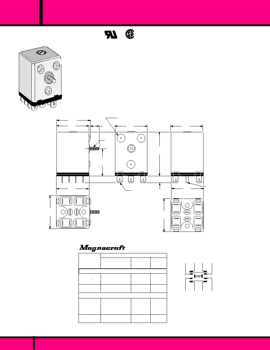
C L A S S
2.06 Max.
(52.3)
1.52
(38.6)
1.60
(40.6)
0.40
(10.1)
8-32
Stud
1.21
(30.7)
.310
(7.8)
1.52
(38.6)
1.52
(38.6)
PLUG-IN,
PLAIN COVER,
NO STUD
3 Standoffs on Stud Mount
Covers only. (Typical)
STUD MOUNT
.250 x .030 Q.C.
Terminal (Typical)
1.56
(39.7)
1.56
(39.7)
3
4
5
6
7
8
9
10
1
2
1.56
(39.7)
1.56
(39.7)
1
2
7
8
3
4
9
10
6
5
.110 x .010 Q.C.
Coil Terminal (Typical)
W97ACSX-3
W97ACSX-4
W97CSX-1
W97CSX-2
W97ACPX-2
W97ACPX-3
W97ACPX-4
W97CPX-1
W97CPX-2
COIL Measured @ 25�C
Nominal
Input
Voltage
PLAIN COVER, PLUG-IN (NO STUD)
STUD MOUNTING STYLE
PART
NUMBERS
-
-
50
200
-
-
-
50
200
8 VA
8 VA
2.5 W
2.5 W
8 VA
8 VA
8 VA
2.5 W
2.5 W
120 VAC
240 VAC, 60 HZ
220 VAC, 50 HZ
12 VDC
24 VDC
24 VAC
120 VAC
240 VAC, 60 HZ
220 VAC, 50 HZ
12 VDC
24 VDC
Nominal
Resistance
(Ohms)
PART NUMBERS SHOWN ALSO AVAILABLE THRU STOCKING DISTRIBUTION.
1
2
CLASS 97 POWER RELAY
PLUG-IN OR SIDE STUD MOUNT
25 AMPS METAL ENCLOSED POWER RELAY
PAGE 31
10
9
8
7
3
4
5
6
WIRING SCHEMATIC
Viewed from Terminal End
OUTLINE DIMENSIONS
Dimensions shown in Inch & (Millimeter)
Nominal
Power
UL Recognized
File No. E43641
97
WEBSITE: www.magnecraft.com - EMAIL:info@magnecraft.com - FAX ON DEMAND 1-800/891-2957 - DOCUMENT 100

WEBSITE: www.magnecraft.com - EMAIL:info@magnecraft.com - FAX ON DEMAND 1-800/891-2957 - DOCUMENT 100
PAGE 32
97
C L A S S
METAL ENCLOSED, 25 AMP - 2 FORM "Z" CONTACTS
SPECIFICATIONS FOR CLASS 97
COIL
Pull-in Voltage:
Dropout Voltage:
Max. allowed voltage:
Maximum Power
Minimum Power:
Duty
Resistance
CONTACTS
Contact Configuration:
Contact Material:
Contact Resistance:
Contact Rating:
TIMING
Operate Time:
Release Time:
DIELECTRIC STRENGTH
Coil to Contacts:
Across Open Contacts:
Pole to Pole:
Contact to Frame:
Insulation Resistance:
TEMPERATURE
Operating:
VIBRATION RESISTANCE
Functional:
SHOCK RESISTANCE
Functional:
LIFE EXPECTANCY
Mechanical (No Load):
Electrical (Rated Load):
Max. Cycle Rate:
MISCELLANEOUS
Terminals:
Enclosure:
Operating Position:
Weight:
AC, 85% of Nominal Voltage or less
DC, 75% of Nominal Voltage or less
110% of nominal voltage
3 Watts
1.6 Watts
Continuous
�
10%
DPDT-NC-NO (DB-DM)
Silver Alloy
50 Milliohms max. (Initial)
25 Amps @ 240 VAC Resistive.
25 Amps @ 277 VAC Resistive.
1 HP @ 120 VAC, 2Hp @ 240 VAC
25 Amps Resistive @ 28 VDC.
35 mS Max. @ Nominal Voltage.
35mS Max. @ Nominal Voltage.
2000 V rms
1500 V rms
2000 V rms
2000 V rms
500 VDC Exceeds 100 Megohms min.
-35�C to +70�C @ Rated Operation.
5g's; 10 to 55 Hz,
10 g's
1 Million Operations
100,000 Operations
1800 per hour
All Terminals on Stud mounted relays are
1/4" x .032 Quick Connect Tabs. Plug-in
relays have 1/4" x .032 Quick Connect
Tabs and .110 Taper Coil Terminals.
Plated Steel
Any
259.4 grams
SEE SECTION 10 FOR MATING SOCKETS

PAGE 33
WEBSITE: www.magnecraft.com - EMAIL:info@magnecraft.com - FAX ON DEMAND 1-800/891-2957 - DOCUMENT 100
1
7
8
14
219DXBP
(4P-NO + 2P-NC )
LOCKING
CLIP
1.468
(37.2)
2.593
(65.5)
.435
(11)
3.406
(86.5)
219BBXP
219XBXP
219ABAP
DPDT + 2 NO
DPDT
DPDT + 1 NO & 1 NC
219XDXP
219FXXP
219DXBP
4PDT
6P-NO
4P-NO + 2P-NC
CONTACTS
12 PIN
CONTACTS
14 PIN
2.593
(65.5)
.435
(11)
.250
(6.35)
3.406
(86.5)
LOCKING
CLIP
3.062
(77.77)
OPTIONAL MANUAL ACTUATOR
13
11
12
14
10
9
8
1
6
5
2
3
4
7
1.468
(37.2)
MODELS AVAILABLE
.250
(6.35)
OPTIONAL MANUAL ACTUATOR
2.625
(66.6)
Make before break and other Contact configurations available
limited only by the number of terminal pins.Contact Factory.
5
2
3
4
6
7
10
8
9
11
12
0.10 Dia. x .435 (2.54 x 11)
Typical of all Pin Dimensions
THE SERIES 219 GENERAL PURPOSE INDUSTRIAL PLUG-IN RELAYS FEATURE
12 PIN AND 14 PIN BASES. THE COIL IS ENCAPSULATED FOR PROTECTION.
NUCLEAR QUALIFIED VERSIONS ARE AVAILABLE. CONSULT FACTORY.
SERIES
219
300 VOLT GENERAL PURPOSE PLUG-IN RELAY
219XDXP
(4PDT )
1
7
8
14
219FXXP
(6P-NO )
1
7
8
14
6
1
7
12
219ABAP
(DPDT + 1NO & 1 NC )
6
1
7
12
219BBXP
(DPDT + 2 N.O.)
6
1
7
12
219XBXP
(DPDT )
WIRING DIAGRAMS
BOTTOM VIEW
UL Recognized
File No. E13224
1
0.10 Dia. x .435 (2.54 x 11)
Typical of all Pin Dimensions

219 XBX P L -24D
Series
219 Industrial plug-in style
Contact Arrangements
XBX (DPDT)
ABA (DPDT + 1 Pole-NO & 1 Pole NC)
BBX (2 Pole-NO & DPDT)
XDX (4 PDT)
FXX (6 Pole-NO)
DXB (4 Pole-NO & 2 Pole-NC)
Standard Features
Polycarbonate Cover- CODE "P"
Optional Features
Indicator Lamp - CODE "L"
Manual Actuator- CODE "M"
130�C Coil - CODE "U"
Bifurcated Contacts - CODE "33"
Perm. Magnet Blowout- CODE "69"
Coil Voltage
AC: 6, 12, 24, 120, 240 (Add "A")
DC: 6, 12, (24-28), 32, 115/125 (Add "D")
Coil Voltages & Frequencies must be specified.
ORDERING CODE
Typical Type No.
* Note: Stock 24 Vdc and 115 Vac relays have nameplates stamped 24-28
and 115-125 Vdc respectively. These relays operate at 80% of the lower
voltages and operate within allowable temperature rises at higher voltages.
250 Vdc - Use 125 Vdc relay and series resistor (6000
, 5 W) not supplied.
Milliamperes
Cold Hot
AC RELAYS 50/60 HZ (COIL DATA @ 60HZ Voltage
6
12
24
120
240
Resistance
Ohms
�
10%
1.1
4.2
15.5
540
2100
1500
750
375
75
32
Milliamperes
Cold Hot
840
410
200
40
17
Impedance
Ohms
7.2
27
120
2700
13,400
Nominal
Voltage
Nominal
Voltage
Resistance
Ohms
�
10%
15.5
63.5
250
375
6200
385
189
96
86
20
304
147
77
62
16
6
12
24 (28)*
32
115/125*
10A
3A
1A
3A
0.1A
0.5A
1.5A
150 mA
0.5A
24 VDC
120 VAC
240 VAC
28 VDC
125 VDC
125 VDC SM
125 VDC DM
250 VDC SM
250 VDC DM
VOLTS
MAKE
30A
30A
30A
30A
30A
30A
30A
30A
30A
10A
10A
10A
10A
10A
10A
10A
10A
10A
10A
10A
5A
10A
0.5A
1.5A
4A
0.5A
1.5A
RESISTIVE
INDUCTIVE
CARRY
DC RELAYS, 1.8 WATTS (2.5 W @ 125VDC)
BREAK
For versions with suffix "69"
Permanent Magnet Blowouts
PAGE 34
WEBSITE: www.magnecraft.com - EMAIL:info@magnecraft.com - FAX ON DEMAND 1-800/891-2957 - DOCUMENT 100
COIL SPECIFICATIONS @ 25�C
CONTACT RATINGS
Struthers-Dunn
SERIES
219
300 VOLT GENERAL PURPOSE PLUG-IN RELAY
SEE SECTION 10
FOR
MATING SOCKETS
COIL
Pull-in, min. AC
Pull-in min. DC
Overvoltage, max.
CONTACTS
Contact Material:
TIMING
Operate Time:
Release Time:
DIELECTRIC STRENGTH
All Mutually Insulated Points:
Insulation :
TEMPERATURE
Rated Operation:
LIFE EXPECTANCY
Mechanical:
Electrical:
MISCELLANEOUS
Enclosure:
Operating Position:
Weight:
85% of Nominal Voltage
80 % of Nominal Voltage
110% of nominal, voltage
Silver Cadmium Oxide, Gold diffused
(Standard)
25 mS Max. @ Nominal Voltage.
20 mS Max. @ Nominal Voltage.
1500 V rms
1/4" over surface, 1/8" thru Air
-10�C to +60�C
10 Million Operations no load
100,000 Operations @ Rated Load.
Clear polycarbonate.
Vertical, Contacts Up
8.5 oz. (241 g) approx.
219 GENERAL SPECIFICATIONS

PAGE 35
RSX 1800
SERIES
INDUSTRIAL PLUG-IN ALARM RELAY 5 AMP, 2 POLE
RSX1800 S 120A
Series
219 Industrial plug-in style Alarm relay
5 Amp, 2 Pole
Design for Trouble Contacts
Operate from N.C. trouble contact- CODE S*
Operate from N.O. Trouble contact- CODE Z*
Coil Voltage
AC: 6, 12, 24, 120, (Add "A")
DC: 6, 12, 24 110-125 (Add "D")
ORDERING CODE
Typical Type No.
* Codes "S" & "Z" are 120 VAC only. All other codes are
"AD" for NC input or "ZZ" for NO input.
Struthers-Dunn
SEE SECTION 10 FOR MATING SOCKETS
The RSX1800 Series Alarm Relay consists of a pair of 2 pole or 3 pole
relays enclosed in a clear plastic cover. Wired to a 12 Pin Industrial plug.
The relay is wired so that it performs the basic functions of Interfacing between
a alarm point and an alarm light and/or an acoustic sounding device.
The RSX1800 operates from a normally closed trouble contact, while the
RSX1800Z operates from a normally open trouble contact. Either a sustained
or momentary alarm condition will energize the relay when signalled by an
external trouble contact. The Alarm can be allowed to continue until the
trouble has been corrected, at which time it automatically resets.
2.625
(66.6)
11
12
1
5
2
3
4
6
7
8
9
10
LOCKING
CLIP
2.593
(65.5)
.435
(11)
3.406
(86.5)
0.10 Dia. x .435 (2.54 x 11)
Typical of all Pin Dimensions
mA
Volts Ohms mA
AC Coils, 50/60Hz
Volts
AC Coils, 50/60Hz
Ohms
6
12
24
120
10.7
41.1
170
4500
200
100
59
10
6
12
24
115-125
35
150
560
11,000
170
80
43
10.5
Measured at 25�C
COIL DATA
1.468
(37.2)
WEBSITE: www.magnecraft.com - EMAIL:info@magnecraft.com - FAX ON DEMAND 1-800/891-2957 - DOCUMENT 100

RSX 1800
SERIES
INDUSTRIAL PLUG-IN ALARM RELAY 5 AMP, 2 POLE
6
1
12
K1
K2
K2
K1
K2
K1
5
2
3
K2
K1
4
K1
DS
Horn
K2
L1
N
L1
Lamp
Test
Alarm
Lamp
M
Flasher
Motor
K1
K2
9
8
7
Reset
No trouble
contact
R
S F T
A
N
Flasher
Contact
Acknowledge
1- Normal
2- Alarm
3- Acknowledge
4- Alarm Contact
Recloses
5- Lamp Out
Automatic
Reset Sequence.
K1 K2 Flasher Horn Lamp
ON
OFF
OFF
On
ON
ON
ON
OFF
On
ON
OFF
ON
OFF
OFF
OFF
OFF
ON
OFF
OFF
OFF
OFF
Flashing
ON
OFF
ON
PAGE 36
WEBSITE: www.magnecraft.com - EMAIL:info@magnecraft.com - FAX ON DEMAND 1-800/891-2957 - DOCUMENT 100
Automatic or Manual
1- Normal
2- Alarm
3- Acknowledge
4- Trouble Contact
Reopens. Auto reset
Manual reset
5- Reset
6- Lamp Test
* External Jumper supplied be Customer.
K1 K2 Flasher Horn Lamp
OFF
ON
ON
OFF
ON
OFF
OFF
ON
ON
OFF
ON
OFF
ON
ON
OFF
ON
OFF
OFF
OFF
OFF
OFF
OFF
ON
OFF
OFF
OFF
OFF
OFF
OFF
Flashing
ON
OFF
ON
OFF
ON
1- Normal
2- Alarm
3- Acknowledge
4- Alarm Contact
Recloses
5- Reset
6- Lamp Test
K1
ON
ON
OFF
OFF
ON
ON
K2 Flasher
OFF
ON
OFF
OFF
OFF
OFF
Horn
OFF
ON
OFF
OFF
OFF
OFF
OFF
Flashing
ON
ON
OFF
ON
ON
OFF
OFF
OFF
ON
ON
Manual (Push-button)
Reset Sequence.
AUTO or MANUAL RESET
RSX1800Z
6
7
8
1
12
K1
K2
K2
K1
K2
K2
K1
5
2
3
K2
K1
4
K1
DS
Horn
N
A
K2
L1
N
L1
Lamp
Test
Flasher
Contact
T
F
S
Alarm
Lamp
M
Flasher
Motor
K1
K2
9
External Jumper
NC Alarm cont.
Acknowledge
6
7
8
1
12
K1
K2
K2
K1
K2
K2
K1
5
2
3
K2
K1
4
K1
DS
Horn
N
A
K2
NC Alarm contact
L1
N
L1
Lamp
Test
Reset
Acknowledge
Flasher
Contact
T
F
S
R
Alarm
Lamp
M
Flasher
Motor
K1
K2
9
MANUAL RESET
RSX1800S
AUTOMATIC RESET
RSX1800S
* OMIT for RESET (RSX1800Z)
MANUAL RESET (RSX1800S)
Lamp
AUTOMATIC RESET (RSX1800S)
CONTACTS
Contact Material:
Rating:
TIMING
Operate Time:
Release Time:
DIELECTRIC STRENGTH
Across open contacts:
Between all mutually
insulated current
carrying parts:
TEMPERATURE
Rated Operation:
LIFE EXPECTANCY
Mechanical:
Electrical:
MISCELLANEOUS
Enclosure:
Operating Position:
Weight:
Silver Cadmium Oxide.
5 AMP, 120Vac/30Vdc Resistive
20 mS Max. @ Nominal Voltage.
25 Milliseconds max.
20 milliseconds max.
500 V rms
1500 V rms
-10�C to +70�C
20 Million Operations no load
500,000 Operations @ Rated Load.
Clear polycarbonate.
Any
8.8 oz (250 g) approx.
GENERAL SPECIFICATIONS
K1 - Alarm/Silencing Relay.
K2 - Alarm/Silencing Relay.
A - Horn & optional Flasher.
TT - Lamp test (optional).
L1 - Line voltage.
R - Reset (optional for
manual reset only.
S - Horn Silence (acknowledge).
F - Flasher (Optional).
N - Neutral.
Relays are supplied only with the
items and wiring shown within the
rectangles in schematics.
NOTE: For additional alarms,
jumper to like terminals as shown.
LEGEND
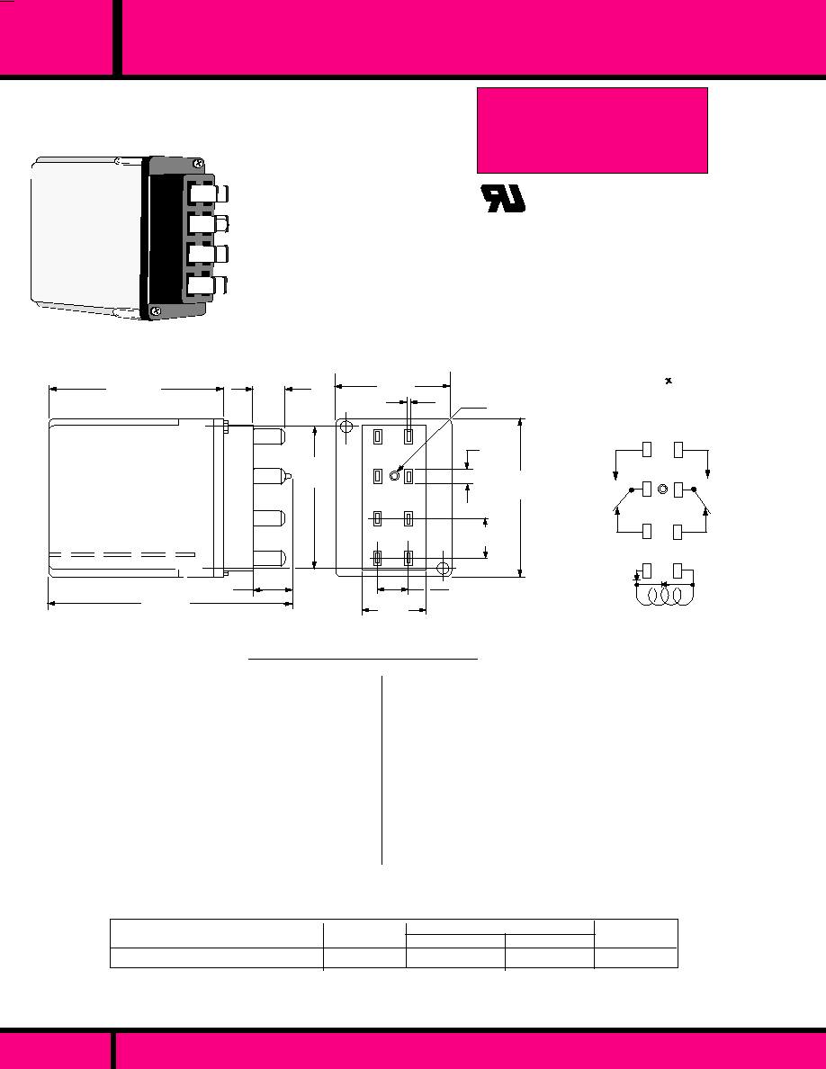
C L A S S
FLASH TRANSFER RELAY SWITCHES TUNGSTEN LOADS
PAGE 37
WEBSITE: www.magnecraft.com - EMAIL:info@magnecraft.com - FAX ON DEMAND 1-800/891-2957 - DOCUMENT 100
Type
Contact
Configuration
Coil Measured at 25�C
W21ACPX-2 /W21ACPXD-5
DPDT
4.0 VA
120VAC
*
Rectified
Dual Marked Part Number
Nominal Voltage
Nominal Power
*
Rectified type coil provides:
1. Chatter Free operation in Brownout conditions down to 85VAC and will not overheat up to 130VAC.
2. Less Power consumption and less Heating.
PART NUMBERS SHOWN ALSO AVAILABLE THRU STOCKING DISTRIBUTION.
COIL
Pull-in Voltage:
Dropout Voltage:
Coil Insulation :
CONTACTS
Contact Material:
Contact Configuration:
Contact Rating:
DIELECTRIC STRENGTH
Across open contacts
Contact to Coil:
Contact to Frame:
TEMPERATURE
Operating:
LIFE EXPECTANCY
Electrical:
Mechanical:
MISCELLANEOUS
Enclosure:
Operating Position:
Weight:
SPECIFICATIONS CLASS 21 RELAY
1
2
3
4
5
v
Rectified Coil
7
8
VIEWED FROM PIN END
WIRING DIAGRAM
6
2.84 Max.
(72.2)
.500
(12.7)
1.85 Max.
(46.9)
.060
(1.5)
.500 Typ.
(12.7)
1.00
(25.4)
2.12.
(53.9)
.600
(15.4)
3.90 Max.
(99.2)
.250 Typ.
(6.35)
.437 Typ.
(11.09)
Polarizing
Pin
2.47 Max.
(62.7)
DIMENSIONS SHOWN ARE IN INCHES AND (MILLIMETERS)
OUTLINE DIMENSIONS
C US
UL Recognized
File No. E43641
Recognized Component mark for
Canada and the United States.
AC: 70% of Nominal @ 20�C or less
10% of Nominal Voltage or more
Class "B" System (130�C) per UL 1446
Silver alloy 3/8" dia.
DPDT
20Amps, 28VDC (Resistive).
1-1/2 HP, 120VAC (Motor)
2HP, 240VAC (Motor)
20Amps, 120VAC (Tungsten Lamp)
10Amps, 240VAC (Tungsten Lamp)
21
CLASS 21
PLUG-IN BASE WITH POLARIZING PIN
DPDT CONTACT CONFIGURATION
SWITCHES TUNGSTEN LAMP LOADS
UP TO 20 AMPS
MEETS NEMA STD. TS 2- 1992
APPROVED BY D.O.T FOR:
California Minnesota Georgia
New York Illinois Texas
Oregon Colorado Missouri
500 V rms
1500 V rms
1500 V rms
-40�C to +84�C
200,000 Operations min. at 20 Amps
Tungsten, 120VAC.
5 Million Operations MIN. (No Load)
Clear Polycarbonate
Vertical contacts up or horizontal
7.2 oz.. 204.7 Grams

10 AMP, HERMETICALLY SEALED, STEEL CAN RELAY
C L A S S
88HP
80% of nominal voltage or less. For DC coils
85% of nominal voltage or less. For AC coils.
10% of nominal voltage or more.
�
10 % measured @ 25 �C
1.5 Watts for DC coils, 3VA for AC coils
DC coils 3.0 Watts max.
Continuous
3/16" silver cadmium oxide, gold flashed.
50 Milliohms maximum initial resistance at rated current
25mS or less at nominal voltage.
20mS or less at nominal Voltage.
1500 V rms
1000 V rms
1500 V rms
1500 V rms
10,000 megohms min. @ 500 VDC
-10�C to +50�C (AC), -10�C to +60�C (DC)
-30�C to 105�C
5 G's
20 G's
5 G's, 10 Hz to 55 Hz
5 G's, 10 Hz to 55 Hz
Hermetically Sealed Steel
Can with octal plug.
8 or 11 pin octal plug-in
Any
5 ozs. 141.7 g approx.
SPECIFICATIONS CLASS 88HP RELAY
COIL
Pull-in voltage:
Dropout:
Coil resistance
Nominal power:
Max.coil Dissipation:
Duty:
CONTACTS
Contact material:
Contact resistance:
TIMING
Operate time:
Release time:
DIELECTRIC STRENGTH
Contacts to coil:
Across open contacts:
Pole to pole
Contacts to frame:
Insulation resistance:
TEMPERATURE
Operating:
Storage:
SHOCK RESISTANCE
Operating:
Non operating:
VIBRATION RESISTANCE
Operating:
Non operating:
MISCELLANEOUS
Enclosure:
Terminals
Operating Position:
Weight:.
NO. OF PINS
OCTAL
STYLE
3.0VA
3.0VA
1.5W
1.5W
1.5W
COIL
Measured @ 25�C
NOMINAL
INPUT
VOLTAGE
NOMINAL
POWER
NOMINAL
RESISTANCE
(OHMS)
8 PIN
11 PIN
8 PIN
8 PIN
11PIN
-
-
100
400
400
120VAC
120VAC
12 VDC
24 VDC
24 VDC
DPDT
3PDT
DPDT
DPDT
3PDT
50/60Hz Operation.
DC OPERATED
W88AHPX-24
W88AHPX-36
W88HPX-33
W88HPX-34
W88HPX-51
PART NUMBERS SHOWN ALSO AVAILABLE THRU STOCKING DISTRIBUTION
SPDT and other special contact combinations along with other coil voltages up to 240VAC are available. Consult Factory.
KR11AGE (or GF) 120
KR14AGE (or GF) 120
KR11DGE (or GF) 12
KR11DGE (or GF) 24
KR14DGE (or GF) 24
CROSS REFERENCE
TO
POTTER & BRUMFIELD
*
*
GF = GOLD FLASHED
AC OPERATED
CONTACT
CONFIGU-
RATION
PART NUMBERS
SEE SECTION 10 FOR MATING SOCKETS
POLES
120 VAC
240 VAC
28 VDC
12 AMP
1/3 HP
10 AMP
1/3 HP
8 AMP
1/2 HP
6 AMP
1.2 HP
10 AMP
10 AMP
CONTACT RATINGS TABLE
2.03
(51.5)
1.53
(38.8)
1.68
(42.8)
OUTLINE DIMENSIONS
Dimensions are shown in Inch and (Millimeter).
DPDT
3PDT
VIEWED FROM PIN END
WIRING DIAGRAM
CLASS 88HP
8 OR 11 PIN OCTAL BASE
HERMETICALLY SEALED STEEL CAN
Enclosure is filled with dry nitrogen,solder sealed and
then electronically leak checked to prevent contamination
of Internal parts. The case is painted gray to protect
against the elements.
PAGE 38
WEBSITE: www.magnecraft.com - EMAIL:info@magnecraft.com - FAX ON DEMAND 1-800/891-2957 - DOCUMENT 100
2 POLE
3 POLE

PRINTED CIRCUIT BOARD
RELAYS
1 TO 30 AMPERES
2
S E C T I O N
2
Page 39

90
91
HI-CURRENT P.C. BOARD RELAYS
H W L
2000 V rms
.394 X .50 X .787
276
SUBMINIATURE EPOXY SEALED
IMMERSION CLEANABLE
STANDARD 0.1 GRID
PATTERN
SINGLE SIDE STABLE DESIGN
5KV SURGE RESISTANCE
COIL TO FRAME.
MEETS 4mm INTERNATIONAL
SPACING COIL TO CONTACT.
SPST-NO, SPDT
(SPST-NO)
10A, 250 VAC/30 VDC
(SPDT)
7 A, 250 VAC/30 VDC
SILVER ALLOY
100 MILLIOHMS (INITIAL)
PAGE 44
NOT AVAILABLE
5, 6, 12, & 24VDC
-
200 MILLIWATTS
- 40� C to + 70� C
10 MILLISECONDS
10 MILLISECONDS
20 MILLION OPERATIONS
100,000 OPERATIONS
H W L
1500 V rms
- 55� C to + 105� C
- 55� C to + 130� C
15 MILLISECONDS
10 MILLISECONDS
10 MILLION OPERATIONS
100,000 OPERATIONS
.805 X 1.08 X 1.30
SILVER CADMIUM OXIDE
50 MILLIOHMS (INITIAL)
2500 V rms
- 55� C to + 85� C
- 55� C to + 130� C
20 MILLISECONDS
20 MILLISECONDS
10 MILLION OPERATIONS
100,000 OPERATIONS
H W L
1.10 X 1.08 X 1.27
SILVER CADMIUM OXIDE
50 MILLIOHMS (INITIAL)
EPOXY SEALED IMMERSION
CLEANABLE.
STANDARD 0.1 GRID PATTERN
CLASS "B" OR "F" INSULATION
SYSTEM
MEETS UL 508 & UL 873 SPACING
EPOXY SEALED IMMERSION
CLEANABLE.
P.C. BOARD OR FLANGE
MOUNT STYLES.
CLASS "F" INSULATION
SYSTEM.
SPADE TERMINALS ACCEPT
1/4" Q.C. CONNECT TERMI-
NALS. & 3/16'" COIL Q.C.
TERMINALS.
S P D T
20 A 240 VAC (NO)
S P D T
20 A 240 VAC (NO)
15 A,240 VAC (NC)
10A, 30 VDC
NOT AVAILABLE
5, 12, 24 & 110 VDC
-
930 MILLIWATTS
24, 120 & 240 VAC
NOT AVAILABLE
2 VA
-
FEATURES
CONTACT DATA
COIL DATA
GENERAL DATA
DIMENSIONS
APPROVALS
CONTACT CONFIGURATION:
MAXIMUM ALLOWABLE
CONTACT LOAD:
CONTACT MATERIAL:
CONTACT RESISTANCE:
AC - VOLTAGE:
DC - VOLTAGE:
P O W E R :
VA,: (AC)
WATTS,: (DC)
AMBIENT TEMPERATURE
OPERATIONAL:
STORAGE:
TIMING VALUES
OPERATE:
RELEASE:
L I F E
MECHANICAL:
ELECTRICAL:
INSULATION
CHARACTERISTICS
DIELECTRIC STRENGTH
RELAY SERIES
PAGE NUMBER
S P S T - N O
30A, 240 VAC
20A, 30 VDC
15 A,240 VAC (NC)
10A, 30 VDC
S P S T - N O
30A, 240 VAC
20A, 30 VDC
Pending
C US
PAGE 45, 46
WEBSITE: www.magnecraft.com EMAIL:info@magnecraft.com FAX ON DEMAND 1-800/891-2957 - DOCUMENT 100
PAGE 47,48
PAGE 40
Magnecraft
Struthers-Dunn

NEW!
H W L
2 A, 24 VDC
1 A, 100 VAC (DPDT)
2A, 120 VAC (SPDT)
50uA, 50mV MIN.
24, 120 & 240 VAC
12, 24 48 & 110 VDC
4 VA
1.7 WATTS
2500 V rms
SILVER CADMIUM OXIDE
100 MILLIOHMS (INITIAL)
EPOXY SEALED IMMERSION
CLEANABLE WITH TAPE SEAL.
PC BOARD OR FLANGE
MOUNT STYLES.
CLASS "F" INSULATION
SYSTEM.
1/4" SPADE TERMINALS
ACCEPT 1/4' Q.C. CONNEC-
TORS.
S P S T - N O
30A, 277 VAC
20A, 28 VDC
D P D T
30A, 277 VAC
20A, 28 VDC (NO)
3A, 277 VAC
3A, 28 VDC (NC)
DC,- 40� C to + 85�C -AC,- +65�C
15 MILLISECONDS
10 MILLISECONDS
5 MILLION OPERATIONS
100,000 OPERATIONS
1.10 X 1.36 X 1.27
H W L
MICRO MINIATURE SIZE
CONFORMS TO FCC PART
68.302, 1500V SURGE
RESISTANCE, FCC 68.304
1000V DIELECTRIC STRENGTH.
EXCELLENT R.F. SWITCHING
CHARACTERISTICS
HIGH SHOCK & VIBRATION
RESISTANCE
PC BOARD MOUNTING
ON 0.1 GRID PATTERN
94V-0 PLASTIC, EPOXY SEALED
SPDT, DPDT
GOLD CLAD SILVER
PALLADIUM CROSS BAR
50 MILLIOHMS, (INITIAL)
500 V rms
- 35� C to + 70� C
4.0 MILLISECONDS
5.0 MILLISECONDS
100 MILLION OPERATIONS
100,000 OPERATIONS
NOT AVAILABLE
5, 12, & 24 VDC
-
330-370 MILLIWATTS
7
NOT AVAILABLE
5, 12, 24 48 & 110 VDC
1 WATT
H W L
2500 V rms
- 55� C to + 85� C
- 55� C to + 130� C
15 MILLISECONDS
15 MILLISECONDS
10 MILLION OPERATIONS
100,000 OPERATIONS
1.10 X 1.08 X 1.27
SILVER CADMIUM OXIDE
75 MILLIOHMS (INITIAL)
EPOXY SEALED IMMERSION
CLEANABLE WITH TAPE SEAL.
P.C. BOARD OR FLANGE
MOUNT STYLES.
CLASS "F" INSULATION SYSTEM.
SPADE TERMINALS ACCEPT
INSULATED 1/4" Q.C. CONNECT
TERMINALS. & 3/16'" COIL
Q.C.TERMINALS.
S P S T - N O
30A, 240 VAC
20A, 30 VDC
SPDT
20 A 240 VAC
20A, 28 VDC (NO)
15A,240 VAC
10A, 28 VDC (NC)
FEATURES
CONTACT DATA
COIL DATA
GENERAL DATA
DIMENSIONS
APPROVALS
CONTACT CONFIGURATION:
MAXIMUM ALLOWABLE
CONTACT LOAD:
CONTACT MATERIAL:
CONTACT RESISTANCE:
AMBIENT TEMPERATURE
OPERATIONAL:
STORAGE:
TIMING VALUES
OPERATE:
RELEASE:
L I F E
MECHANICAL:
ELECTRICAL:
INSULATION
CHARACTERISTICS
DIELECTRIC STRENGTH
RELAY SERIES
PAGE NUMBER
AC - VOLTAGE:
DC - VOLTAGE:
P O W E R :
VA,: (AC)
WATTS,: (DC)
NEW!
9A
92
C US
C US
PAGE 49, 50
PAGE 51, 52
PAGE 53, 54
C US
WEBSITE: www.magnecraft.com EMAIL:info@magnecraft.com FAX ON DEMAND 1-800/891-2957 - DOCUMENT 100
HI-CURRENT & MICRO MINIATURE P.C. RELAYS
.428 X .410 X .410
PAGE 41
Magnecraft
Struthers-Dunn

PAGE 42
1500 V rms
- 40� C to +70� C (272)
20 MILLISECONDS
10 MILLISECONDS
10 MILLION OPERATIONS
100,000 OPERATIONS
H W L
178
.620 X .650 X .890
SPDT
5 AMP @ 125/250VAC, 30VDC
(CLASS 178RE1-)
12 AMP @ 120VAC, 28VDC
10AMP @ 125/250 VAC, 30 VDC
(CLASS 178URE1-)
NOT AVAILABLE
5, 12, & 24 VDC
400 MILLIWATTS
MINIATURE EPOXY SEALED.
P.C. BOARD MOUNTING.
SWITCHES UP TO 12 AMP
LOADS.
CLASS "B" OR "F" INSULATION
SYSTEM
IMMERSION CLEANABLE.
DISPLACES APPROXIMATELY
.43 CUBIC INCH.
NOT AVAILABLE
3, 5, 6, 12, & 24 VDC
400 MILLIWATTS
DUST COVERED
DISPLACES APPROXIMATELY
1.1 CUBIC INCH.
VARIETY OF MOUNTING
CONFIGURATIONS.
TV-5 RATINGS AVAILABLE.
49
H W L
1.14 X .759 X 1.25
- 55� C to + 85� C
- 55� C to + 130� C
10 MILLISECONDS
7 MILLISECONDS
50 MILLION OPERATIONS
100,000 OPERATIONS
SILVER, GOLD PLATED,
SILVER CADMIUM OXIDE
100 MILLIOHMS (INITIAL)
1500 V rms
SPDT
3 AMPS @ 120 VAC/ 28 VDC
5 & 10 AMP @ 240VAC/28VDC
H W L
.570 X .895 X 1.10
NOT AVAILABLE
5, 12, & 24 VDC
-
330-370 MILLIWATTS
- 35� C to + 70� C
4.0 MILLISECONDS
5.0 MILLISECONDS
100 MILLION OPERATIONS
100,000 OPERATIONS
MINIATURE SIZE
CONFORMS TO FCC PART
68.302, 1500V SURGE
RESISTANCE, FCC 68.304
1000V DIELECTRIC STRENGTH.
EXCELLENT R.F. SWITCHING
CHARACTERISTICS
HIGH SHOCK & VIBRATION
RESISTANCE
PC BOARD MOUNTING ON 0.1
GRID PATTERN.
SPDT, DPDT
GOLD CLAD SILVER
PALLADIUM CROSS BAR
50 MILLIOHMS MAX (INITIAL)
500 V rms
2 A, 24 VDC
1 A, 100 VAC (DPDT)
2A, 120VAC )SPDT)
50uA, 50mV MIN.
60
C US
C US
PAGE 57, 58
PAGE 59 , 60
PAGE 55, 56
MINIATURE P.C. BOARD RELAYS
SILVER CADMIUM OXIDE
100 MILLIOHMS (INITIAL)
Magnecraft
Struthers-Dunn
WEBSITE: www.magnecraft.com EMAIL:info@magnecraft.com FAX ON DEMAND 1-800/891-2957 - DOCUMENT 100

FEATURES
CONTACT DATA
COIL DATA
GENERAL DATA
DIMENSIONS
APPROVALS
CONTACT CONFIGURATION:
MAXIMUM ALLOWABLE
CONTACT LOAD:
CONTACT MATERIAL:
CONTACT RESISTANCE:
AC - VOLTAGE:
DC - VOLTAGE:
P O W E R :
VA,: (AC)
WATTS,: (DC)
AMBIENT TEMPERATURE
OPERATIONAL:
STORAGE:
TIMING VALUES
OPERATE:
RELEASE:
L I F E
MECHANICAL:
ELECTRICAL:
INSULATION
CHARACTERISTICS
DIELECTRIC STRENGTH
RELAY SERIES
PAGE NUMBER
MINIATURE SIZE
ENCLOSED SEE THRU COVER
WITH P.C. TERMINALS.
AC OR DC OPERATION
5 AMP RESISTIVE OR 3 AMP
INDUCTIVE SWITCHING.
H W L
1500 V rms
24, 120 VAC
12, 24 VDC
1.2 VA
1.2 W
- 45� C to + 70� C
20 MILLISECONDS
20 MILLISECONDS
AC, 50 M. DC, 100M OPERATIONS
100,000 OPERATIONS
D P D T
.905 X .728 X 1.07
PAGE 63
H W L
.811 X .512 X 1.14
4000 V rms
SILVER CADMIUM OXIDE
50 MILLIOHMS (INITIAL)
- 20� C to + 70� C
15 MILLISECONDS
10 MILLISECONDS
20 MILLION OPERATIONS
150,000 OPERATIONS
76
SPECIAL ORDER
5,6, 12, 24 & 48 VDC
520 MILLIWATTS
SPDT, DPDT
10 AMPS @
250 VAC/
30 VDC
SPDT
16AMPS @
240 VAC/
24 VDC
PAGE 43
WEBSITE: www.magnecraft.com EMAIL:info@magnecraft.com FAX ON DEMAND 1-800/891-2957 - DOCUMENT 100
UL RATED - 5A, 120VAC, NON
UL RATED - 5A, 30 VDC
3A, 120VAC INDUCTIVE.
1/8 HP, 120 VAC
SEE SECTION 10
FOR
MATING SOCKETS
NEW!
1330 & 1335
EPOXY SEALED IMMERSION
CLEANABLE.
MEETS 8 MILLIMETER
SPACING COIL TO CONTACTS
MEETS 4KV DIELECTRIC
WITHSTANDING VOLTAGE.
C US
PAGE 61, 62
LIMITED RATINGS
MINIATURE P.C. BOARD RELAYS
SILVER CADMIUM OXIDE
100 MILLIOHMS MAX.
(INITIAL)
Magnecraft
Struthers-Dunn

-40�C to +70�C
10g's 10 to 55Hz, .06" DA
100g's no damage
100,000 Operations
20 Million Operations
A n y
Plastic Cover, Epoxy sealed,
0.2 oz. ( 5.5 grams) approx.
C O I L
Pull-in Voltage:
Dropout Voltage:
Max. allowed voltage:
Coil Resistance:
Nominal Power:
C O N T A C T S
Contact Material:
Contact Resistance:
TIMING
Operate Time:
Release Time:
DIELECTRIC STRENGTH
Contacts to Coil:
Across open contacts:
Surge voltage resistance:
Insulation Resistance:
75% of Nominal Voltage or less
10% of nominal voltage or more
110% of nominal voltage.
�
10%
200mW Approx.
Silver Alloy
100 Milliohms initial @ 6VDC, 1 Amp
10 mS Max. @ Nominal Voltage.
10 mS Max. @ Nominal Voltage.
2000 V rms
1000 V rms
5000 V rms between coil and contacts
500 VDC Exceeds 1000 Megohms min..
SPST-NO
.015 x .030
(.4 x .8) 3 Places
0.50
(12.7)
.138
(3.5)
OUTLINE DIMENSIONS
Dimensions shown are in "Inch" and ( Millimeter)
.787 Max.
(20)
.394
Max.
(10)
0.20 Dia.
(0.5) 2 Coil Terminals
CIRCUIT BOARD SPACING
Layout shown is on a 0.100 Grid
ACTUAL SIZE
BOTTOM VIEW
-
+
SPDT
+
-
.051 Dia.
(1.3)
5 Places
SERIES 276
DTL COMPATIBLE
SINGLE SIDE STABLE DESIGN
5KV SURGE RESISTANCE COIL TO CONTACT
MEETS INTERNATIONAL SPACING -4 mm COIL TO CONTACT
SPECIFICATIONS SERIES 276
T E M P E R A T U R E
Operating::
VIBRATION RESISTANCE
Functional:
SHOCK RESISTANCE
Functional:
L I F E
Electrical (Rated Load):
Mechanical ( No Load):
M I S C E L L A N E O U S
Operating Position:
Enclosure:
Weight:
WIRING DIAGRAM
BOTTOM VIEW
WEBSITE: www.magnecraft.com EMAIL:info@magnecraft.com FAX ON DEMAND 1-800/891-2957 - DOCUMENT 100
276
SERIES
MINIATURE POWER RELAY 10 AMP, P.C. MOUNTABLE
SPST-NO
SPST-NO
SPST-NO
SPST-NO
SPDT
SPDT
SPDT
SPDT
Nominal
Resis-
tance
(Ohms)
Nominal
Input
Voltage
5 VDC
6 VDC
12 VDC
24 VDC
5 VDC
6 VDC
12 VDC
24 VDC
125
180
720
2880
125
180
720
2880
Nominal
power
(mW)
200
200
200
200
200
200
200
200
COIL - Measured at 25�C
276AXXH-5D
276AXXH-6D
276AXXH-12D
276AXXH-24D
276XAXH-5D
276XAXH-6D
276XAXH-12D
276XAXH-24D
Part Numbers
Contact
Configuration
Struthers-Dunn
PAGE 44
SPST-NO
10 AMPS @ 250 VAC
10 AMPS @ 30 VDC
300 WATTS (DC)
2500 VA (AC)
10 AMPERES
125 VDC
380 VAC
1/6 HP @ 120 VAC
B300
SPDT
7 AMPS @ 250 VAC
7 AMPS @ 30 VDC
210 WATTS (DC)
1750 VA (AC)
7 AMPERES
125 VDC
380 VAC
1/10 HP @ 120 VAC
B300
NOTE: Coil polarity must be observed. Relay is polarized with a permanent magnet and will not
be damaged with reverse polarity but will not operate with reverse polarity.
PART NUMBERS SHOWN ALSO AVAILABLE THRU STOCKING DISTRIBUTION.
CONTACT LOAD RATINGS
LOAD CONDITION
RESISTIVE LOADS:
* MAX. SWITCHING POWER:
* MAX. SWITCHING CURRENT:
* MAX. SWITCHING VOLTAGE:
MOTOR:
PILOT DUTY:
* Voltage current, and power ratings in the table above are
independent maximums and no single value is to be exceeded.
LOW LEVEL LOADS: NOT SUITABLE BELOW
20 WATTS

30 AMP MINIATURE P.C. BOARD RELAY
90
.500
(12.7)
.400
(10.1)
.550
(13.9)
.700
(17.8)
.350
(8.9)
.600
(15.2)
.150
(3.8)
.100
(2.54)
A B A
B A
NOT USED
ON
CLASS "F"
STYLES
FIG. "A"
FIG. "C"
FIG."B"
FIG."D"
1.08 MAX.
(27.4)
.693
(17.6)
.78
(19.8)
.96
(24.3)
1.30.
(33)
WIRING DIAGRAM
BOTTOM VIEW
PC BOARD LAYOUT
(Bottom View )
.100
(2.54)
.208 Max.
(5.28)
.025 x .025
(.64 x .64)
.045 x .045
(1.1 x 1.1)
.031 x .062
(.8 x 1.6)
.150
(3.8)
Pin removed
on Class "F"
styles.
OUTLINE DIMENSIONS
(Actual Size)
Dimensions are in Inchs and (Millimeters)
Drill "A" Holes .086 (2.19).
Drill "B" Holes .046 (1.17).
.830 MAX.
(21.08)
Stand0ff
(qty. 5)
C L A S S
SPDT
SPDT
SPST-NO
SPST-NO
C US
UL Recognized
File No. E13224
Recognized Component mark for
Canada and the United States.
Pending
VENT HOLE NIB
CLASS 90 RELAY
SPST-N.O. or SPDT
CLASS "B" OR "F" INSULATION
EPOXY SEALED.
BREAKAWAY NIB
OVER VENT HOLE
(REMOVED AFTER
CLEANING).
WEBSITE: www.magnecraft.com - EMAIL:info@magnecraft.com - FAX ON DEMAND 1-800/891-2957 - DOCUMENT 100
PAGE 45
Class 90 printed circuit board relays provide
an inexpensive means of switching loads up to
30 amps. Designed primarily for the appliance
industry and HVAC markets, they are also well
suited for load management, automotive and
other applications.
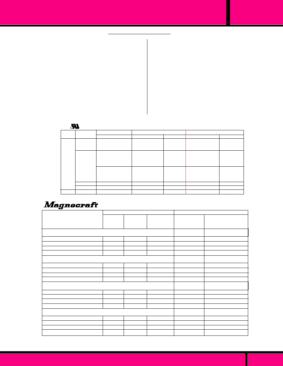
SPECIFICATIONS CLASS 90
SILVER CADMIUM OXIDE CONTACT RATINGS
30A @ 240VAC
20A @ 277 VAC
12A @ 277 VAC
1HP @ 125VAC
3/4 HP @ 125VAC
2HP @ 240/250VAC
470VA @ 125/240VAC
30FLA/96LRA, 125VAC
30FLA/80LRA, 240VAC
20FLA/60LRA, 277VAC
27FLA/82.8LRA,125VAC
N.O.
20A @ 240VAC
20A @ 277 VAC
12A @ 277 VAC
1HP @ 125VAC
3/4HP @ 125VAC
2HP @ 240/250VAC
470VA @ 125/240VAC
30FLA/96LRA, 125VAC
30FLA/80LRA, 240VAC
20FLA/60LRA, 277VAC
27FLA/82.8LRA,125VAC
100,000
100,000
6,000
30,000
100,000
1,000
100,000
30,000
30,000
100,000
100,000
25,000
6,000
100,000
TV 3 @ 250VAC
TV 3 @ 250VAC
6Amp @ 277VAC
6Amp @ 277VAC
20A @ 5-30VDC
20A @ 5-30VDC
Motor
SPST
N.O.
100,000
100,000
6,000
30,000
30,000
30,000
100,000
100,000
6,000
100,000
OPERATIONS
10A @ 5-30VDC
3 AMP@ 277VAC
TV 3 @ 250VAC
R
30 AMP MINIATURE P.C. BOARD RELAY
TEMPERATURE
Operating:
Storage:
Relative Humidity:
Atmospheric Pressure:
VIBRATION RESISTANCE
Functional:
SHOCK RESISTANCE
Functional:
Mechanical:
LIFE
Electrical (Rated Load):
Mechanical (No Load):
MISCELLANEOUS
Operating position:
Enclosure:
Weight:
-55�C to +105�C
-55�C to +130�C
Up to 93% @ 40�C.
650 to 800 mmHg.
10 to 55 Hz @ Double Amplitude of 1 mm.
10 g's for 11 mS, no Contact Opening > 100uS,
100 g's
Operations: See Table Below
10 million Operations .
Any
94V-0 Flammability rating, Epoxy sealed
Immersion cleanable.
27 Grams approximately.
COIL
Pull-in Voltage:
Dropout Voltage:
Coil Power:
Duty:
Insulation System:
Coil Resistance:
CONTACTS
Contact Configuration:
Contact Material:
Contact Resistance:
TIMING
Operate Time:
Release Time:
DIELECTRIC STRENGTH
Across open Contacts
Contacts to Coil:
Insulation Resistance:
75% of Nominal Voltage or less
10% of Nominal Voltage or more.
2.8 Watts Max.
Continuous
Class "B" (130�C) or Class "F" (155�C
�
10% measured at 25�C
SPST-N.O., SPDT
Silver Cadmium Oxide.
50 Milliohms Max. Initial Value.
15 mS Max. @ Nominal Voltage.
10mS Max. @ Nominal Voltage.
1000 V rms
1500 V rms
500 Megohms under normal conditions
100 Megohms High Temp, High humidity.
FIGURE "C" & "D" MEETS UL 508 & UL 873 SPACING .
SPDT
OPERATIONS
1/4HP @ 125VAC
1/2HP @ 250VAC
275VA @ 125/240VAC
10FLA/33LRA, 125VAC
10FLA/33LRA,240VAC
2-10A @ 240VAC, (i&R)
15 AMP @ 240 (i)
6A @ 277VAC, I&R
N.C.
SPDT
AC
Voltage
DC
Load Type
Resistive
Resistive
Ind. & Res.
Tungsten
Ballast
Resistive
PAGE 46
WEBSITE: www.magnecraft.com - EMAIL:info@magnecraft.com - FAX ON DEMAND 1-800/891-2957 - DOCUMENT 100
5VDC
12VDC
24VDC
110VDC
5VDC
12VDC
24VDC
110VDC
5 VDC
12 VDC
24 VDC
110VDC
5 VDC
12 VDC
24 VDC
110VDC
NOMINAL
INPUT
VOLTAGE
NOMINAL
RESISTANCE
(Ohms)
27
155
660
13,450
27
155
660
13,450
27
155
660
13,450
27
155
660
13,450
NOMINAL
POWER
(mW)
930
930
870
900
930
930
870
900
930
930
870
900
930
930
870
900
W90S1D12-5
W90S1D12-12
W90S1D12-24
W90S1D12-110
W90S5D12-5
W90S5D12-12
W90S5D12-24
W90S5D12-110
W90S1D42-5
W90S1D42-12
W90S1D42-24
W90S1D42-110
W90S5D42-5
W90S5D42-12
W90S5D42-24
W90S5D42-110
SPST-NO , ( 30 AMP ) CLASS "B" INSULATION, FIG "A" WIRING
SPDT, ( 20 AMP ) CLASS "F" INSULATION, FIG "D" WIRING
SPST-NO, ( 30 AMP ) CLASS "F" INSULATION, FIG "C" WIRING
SPDT, ( 20 AMP ) CLASS "B" INSULATION, FIG "B" WIRING
CROSS REFERENCE
POTTER &
BRUMFIELD
T90S1D12-5
T90S1D12-12
T90S1D12-24
T90S1D12-110
T90S5D12-5
T90S5D12-12
T90S5D12-24
T90S5D12-110
T90S1D42-5
T90S1D42-12
T90S1D42-24
T90S1D42-110
T90S5D42-5
T90S5D42-12
T90S5D42-24
T90S5D42-110
OMRON
G8P1114PB1USDC5
G8P1114PB1USDC12
G8P1114PB1USDC24
G8P1114PB1USDC110
G8P114PB1USDC5
G8P114PB1USDC12
G8P114PB1USDC24
G8P114PB1USDC110
G8P1114PCFUSDC5
G8P1114PCFUSDC12
G8P1114PCFUSDC24
G8P1114PCFUSDC110
G8P114PCFUSDC5
G8P114PCFUSDC12
G8P114PCFUSDC24
G8P114PCFUSDC110
COIL Measured @ 25�C
PART NUMBERS
PART NUMBERS SHOWN ALSO AVAILABLE THRU STOCKING DISTRIBUTION.
90
C L A S S

30 AMP PC or FLANGE MOUNT MINIATURE RELAY
1.270 Max.
(32.26)
N.C.
N.O.
A1
A1
COM.
A1
1.27 Max.
(32.26)
1.713
�
.010
(43.51
�
.25)
1.980 Max.
(50.29)
N.C.
N.O.
A1
A1
COM.
A1
B1
B1
.071Rad. (1.80) For #6 screw ( 2 places)
A1 = .250 x .032 (6.35 x .81) Quick Connect Terminal
B1 = .187 x .020 (4.78 x .508) Quick Connect Terminal
1.10 Max.
(27.94)
1.080 Max.
(27.43)
.250 Max.
(6.35)
.500
(12.7)
.300
(7.62)
.250 Max.
(6.35)
.100
(2.54)
.150
(3.81)
.700
(17.8)
A
A
A
B
B
.550
(13.9)
HOLE "A" = .081 (005) Dia.
HOLE "B" = .043 (003) Dia.
Dimensions are in "inches" & (Millimeters)
WIRING DIAGRAM
BOTTOM VIEWS
PC BOARD DRILL PATTERN
BOTTOM VIEWS
.032 x .62
(.81 x 1.57)
.045 x .046
(1.14 x 1.14)
.025 x .025
(.63 x .63)
2 places
.130
�
.020
(3.30
�
.51)
FIGURE
"A"
P.C.
MOUNT
FIGURE
"B"
FLANGE
MOUNT
OUTLINE DIMENSIONS
(Actual Size)
C L A S S
91
CLASS
91 RELAY
AC COIL VOLTAGES
30 AMP SWITCHING
CLASS "F" INSULATION
PC or FLANGE MOUNTED.
* REMOVABLE TAPE SEAL
OVER VENT HOLE
(REMOVED AFTER
CLEANING).
SPDT
SPST-NO
PAGE 47
*Tape over vent hole is only supplied
on the P.C. terminal versions of this
relay.
WEBSITE: www.magnecraft.com - EMAIL:info@magnecraft.com - FAX ON DEMAND 1-800/891-2957 - DOCUMENT 100
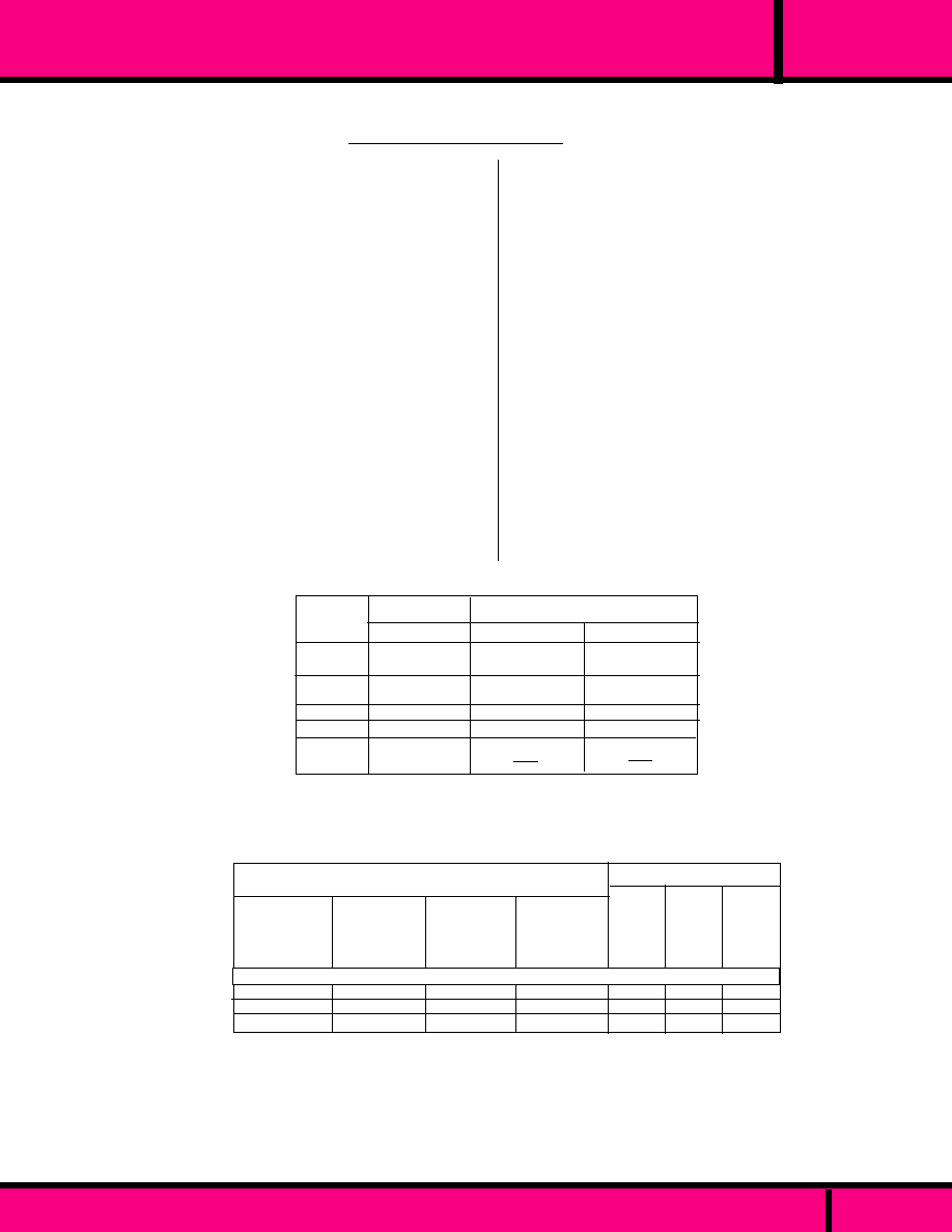
91
30 AMP PC or FLANGE MOUNT MINIATURE RELAY
C L A S S
10A @ 240VAC
10A @ 28VDC
1/4HP @ 120VAC
1/2HP @ 240VAC
hp
RATING
30A @ 240VAC
20A @ 28VDC
1 HP @120VAC
2HP @ 240VAC
20A @ 240VAC
20A @ 28 VDC
1 HP @ 125VAC
2HP @ 240VAC
TV-5, 120VAC
TV-5, 120VAC
TV-3, 120VAC
Tungsten
10A, 277VAC
Ballast
10A, 277VAC
3A, 277VAC
N.O.
N.O.
N.C.
LRA/FLA
80/30 @ 240AC
20/7 @ 240AC
50/20 @ 240AC
50/60Hz
98/22 @ 120AC
Coil measured @ 25� C
24 VAC
120 VAC
240 VAC
-
-
-
2 VA
2 VA
2 VA
NOMINAL
RESIS-
TANCE
(Ohms)
NOMINAL
POWER
(VA)
NOMINAL
INPUT
VOLTAGE
SPECIFICATIONS CLASS 91
-55�C to +85�C
-55�C to +130�C
10 to 55Hz 1.5 mm max. No contact
opening >
100 uS
10 g's for 11 mS, No contact Opening
> 100 uS
100 g's
100,000 Operations
1 million Operations (AC)
10 million Operations (DC)
Any
Epoxy sealed immersion clean-
able suitable for automatic circuit board
processing. Max. exposure
to temperature is 6 sec. @ 300�C.
1/4" Q.C. Contacts, 3/16" Q.C. Coil
33 Grams, 1.2 oz approx.
TEMPERATURE
Operating:
Storage:
VIBRATION RESISTANCE
Functional:
SHOCK RESISTANCE
Functional:
Mechanical:
LIFE
Electrical (Rated Load)
Mechanical (No Load):
MISCELLANEOUS
Operating Position:
Enclosure:
Terminals:
Weight:
COIL
Pull-in Voltage AC:
Dropout voltage:
Max. coil voltage:
Power consumption:
Duty:
Insulation System:
Coil Resistance
CONTACT
Contact Configuration:
Contact Material:
Switching voltage:
Contact Resistance:
Minimum Load:
TIMING
Operate Time:
Release Time:
DIELECTRIC STRENGTH
Between Open Contacts:
Contacts to coil:
Insulation Resistance
85% of Nominal Voltage or Less
10% of Nominal voltage or More
120% Max.
2.0VA max. AC Coils
Continuous
Class "F" (155�C)
�
10% measured @ 25�C
SPST-N.O., SPDT
Silver Cadmium Oxide
277 Vac, 30VDC max.
50 Milliohms @ 100mA, 6VDC Max.
1A, 5VDC, 12VAC
20 mS max
20 mS max.
1500 V rms
2500V rms
1000 m
min. @ 500 VDC
W91S1A22-24
W91S1A22-120
W91S1A22-240
SPST-NO
30AMP
P.C. MT.
FIGURE "A"
W91S5A22-24
W91S5A22-120
W91S5A22-240
SPDT
20AMP
P.C. MT.
FIGURE "A"
W91S1A32-24
W91S1A32-120
W91S1A32-240
SPST-NO
30AMP-
FLANGE MT.
FIGURE "B"
W91S5A32-24
W91S5A32-120
W91S5A32-240
SPDT
20AMP
FLANGE MT.
FIGURE "B"
PART NUMBERS
AC OPERATED COIL
SPST-NO
SPDT
50/60Hz
RESISTIVE
LOAD
PAGE 48
PART NUMBERS SHOWN ALSO AVAILABLE THRU STOCKING DISTRIBUTION.
CONTACT RATINGS
WEBSITE: www.magnecraft.com - EMAIL:info@magnecraft.com - FAX ON DEMAND 1-800/891-2957 - DOCUMENT 100
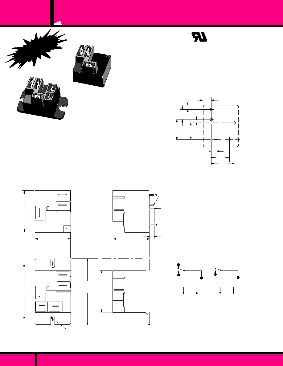
NEW!
WIRING DIAGRAM
BOTTOM VIEWS
1.270 Max.
(32.26)
1.080 Max.
(27.43)
1.10 Max.
(27.94)
OUTLINE DIMENSIONS
(Actual Size)
Dimensions are in "inches" & (Millimeters)
.032 x .62
(.81 x 1.57)
.045 x .045
(1.14 x 1.14)
.025 x .025
(.63 x .63)
2 places
.130
�
.020
(3.30
�
.51)
1.980 Max.
(50.29)
1.713
�
.010
(43.51
�
.25)
1.27 Max.
(32.26)
B1
B1
.071Rad. (1.80) For #6 screw ( 2 places)
NC
NO
COM
NC
NO
COM
FIGURE
"A"
P.C.
MOUNT
A1
B1
B1
A1
A1
A1
A1
A1
A1 = .250 X .032 (6.35 X .81) Quick Connect Terminal
B1 = .187 x .020 (4.78 x .508) Quick Connect Terminal
FIGURE
"B"
FLANGE
MOUNT
C L A S S
30 AMP PC or FLANGE MOUNT MINIATURE RELAY
C US
UL Recognized
File No. E43641
SPST-NO
SPDT
Recognized Component mark for
Canada and the United States.
9A
PAGE 49
.250 Max.
(6.35)
.500
(12.7)
.140 Max.
(3.56)
.150
(3.81)
.700
(17.8)
A
A
A
B
B
.600
(15.24)
.300
(7.62)
.100
(2.54)
.550
(13.97)
PC BOARD DRILL PATTERN
BOTTOM VIEWS
HOLE "A" = .081
�
.005 Dia.
(2.06 x .13)
HOLE "B" = .043
�
.08 Dia.
(1.09 x .08)
CLASS
9A RELAY
30 AMP SWITCHING.
CLASS "F" INSULATION.
PC or FLANGE MOUNTED.
EPOXY SEALED WITH
REMOVABLE TAPE SEAL
OVER VENT HOLE
(REMOVED AFTER
CLEANING).
WEBSITE: www.magnecraft.com - EMAIL:info@magnecraft.com - FAX ON DEMAND 1-800/891-2957 - DOCUMENT 100

Coil measured @ 25� C
W9AS1D22-5
W9ASID22-12
W9ASID22-24
W9ASID22-48
W9ASID22-110
SPST-NO
30AMP
P.C. MT.
FIGURE "A"
W9AS5D22-5
W9AS5D22-12
W9AS5D22-24
W9AS5D22-48
W9AS5D22-110
SPDT
30AMP
P.C. MT.
FIGURE "A"
W9AS1D52-5
W9ASID52-12
W9ASID52-24
W9ASID52-48
W9ASID52-110
SPST-NO
30AMP-
FLANGE MT.
FIGURE "B"
W9AS5D52-5
W9AS5D52-12
W9AS5D52-24
W9AS5D52-48
W9AS5D52-110
SPDT
30AMP
FLANGE MT.
FIGURE "B"
5
12
24
48
110
25
144
576
2,304
12,100
DC OPERATED COIL
1W
1W
1W
1W
1W
NOMINAL
RESIS-
TANCE
(Ohms)
NOMINAL
POWER
(Watts)
NOMINAL
INPUT
VOLTAGE
PART NUMBERS SHOWN ALSO AVAILABLE THRU STOCKING DISTRIBUTION.
PART NUMBERS
SPECIFICATIONS CLASS 9A
-55�C to +85�C
-55�C to +130�C
10 to 55Hz 1.65 mm
max. No contact opening >
100 uS
10 g's for 11 mS, No contact Opening
> 100
�
S
100 g's
100,000 Operations
10 million Operations Typical
Any
Epoxy sealed immersion cleanable
suitable for automatic circuit board
processing. Max. exposure soldering
temperature is 4 sec. @ 500�F.
94V-O Flammability rating.
1/4" Q.C. & safety wells accept insulated
Female Q.C. terminals.
33 Grams, 1.2 oz approx.
TEMPERATURE
Operating:
Storage:
VIBRATION RESISTANCE
Functional:
SHOCK RESISTANCE
Functional:
Mechanical:
LIFE
Electrical (Rated Load)
Mechanical (No Load):
MISCELLANEOUS
Operating Position:
Enclosure:
Enclosure:
Terminals:
Weight:
COIL
Pull-in Voltage:
Dropout voltage:
Max. coil voltage:
Power consumption:
Duty:
Insulation System:
Coil Resistance
CONTACT
Contact Configuration:
Contact Material:
Switching voltage:
Contact Resistance:
Minimum Load:
TIMING
Operate Time:
Release Time:
DIELECTRIC STRENGTH
Between Open Contacts:
Contacts to coil:
Insulation Resistance
75% of Nominal Voltage or Less
10% of Nominal voltage or More
120% Max.
2.8 Watts max.
Continuous
Class "F" (155�C)
�
10% Measured @ 25�C
SPST-N.O., SPDT
Silver Cadmium Oxide
277 VAC, 28VDC max.
75 Milliohms @ 1 min, rated current
(switched)
1A, 5VDC, 12VAC
DC:15 mS typ. including bounce
DC:15mS typ. including bounce
1500 V rms
2500V rms
1000 m
min. @ 500 VDC, 25�C 50% RH
30 AMP PC or FLANGE MOUNT MINIATURE RELAY
C L A S S
9A
PAGE 50
WEBSITE: www.magnecraft.com - EMAIL:info@magnecraft.com - FAX ON DEMAND 1-800/891-2957 - DOCUMENT 100
GENERAL PURPOSE
RESISTIVE
RESISTIVE HEATER
MOTOR (HP)
MOTOR
FLA/LRA
TUNGSTEN
BALLAST
PILOT DUTY
LOAD
VOLTAGE
N.O.
RATING
N.C.
N.O.
SPDT
N.C.
100,000
100,000
100,000
100,000
1,000
1,000
30,000
30,000
25,000
6,000
6,000
AC Measured @ 50/60Hz
10A
15A
10A
-
1/4 HP
1/2 HP
-
12/30A
-
3A
275 VA
20A
20A
20A
-
1 HP
2 HP
-
30/80A
TV-5
10A
470 VA
*15A
15A
10A
-
1/4 HP
1/2 HP
-
12/30A
-
3A
275 VA
30A
20A
20A
25A
1 HP
2 HP
22/98A
30/80A
TV-5
10A
470 VA
240 VAC
240 VAC
28 VDC
240 VAC
125 VAC
240 VAC
120 VAC
240 VAC
240 VAC
277 VAC
240 VAC
OPERATIONS
Meets UL 508, UL 873 and UL 1950 - 1/8" thru air - 1/4" over surface (See Foot notes)
* 15 Amp general purpose rating on SPST-NC contact valid only under UL 508 column B spacings and UL
873 columns B, C & D spacings. Derate to 10 Amps when used under UL 873 columns E & F spacings
and UL 1950.
15 Amp resistive rating on SPST-NC contacts and SPDT contacts (Normally closed side only) valid only
under UL 873 columns E & F spacings. Derate to 10 Amps when used under UL 508 Column B spacings,
under UL 873 columns B, C & D spacings and UL 1950.
The resistance heater rating is not a discreet UL heater rating but is a valid UL rating that is derived
from the UL general purpose category in the above table of contact ratings.
FLA = Full load Amps, LRA = Locked rotor Amps.
CONTACT RATINGS
SPST

Note: An alternate P.C. Board
layout Utilizes .076
�
.003 diameter
holes on the layout above. Use of
retangular holes is recommended
for improved solderability.
*Tape over vent hole is only supplied
on the P.C. terminal versions of this
relay.
0
1
6
8
7
2
4
3
WIRING DIAGRAM
.309
�
.005
(7.85
�
.13)
.585
�
.005
(14.8
�
.13)
1.618 TYP
(41.10
�
.51)
1.00
�
.010
(25.40)
HOLE "A" = .072 x .050 typ.
(1.83)
HOLE "B" = .052 x .050 typ.
(1.32)
.185 TYP
(4.70)
.630
�
.005
(16.00)
.162
(4.12)
.203 TYP
(5.16)
HOLE "B"
HOLE "A"
PC BOARD DRILL PATTERN
0
1
6
2
8
4
TOP VIEW
Only necessary terminals
are present on single
throw styles.
BOTTOM VIEWS
DPDT
DPST-NO
.250 TYP
(6.35)
.630
�
.005
(16.00)
.032 TYP
(0.81)
1.00
�
.010
(25.40)
.309
�
.005
(7.85
�
.13)
.585
�
.005
(14.8
�
.13)
1.618 TYP
(41.10
�
.51)
1.36 Max.
(34.54)
2.35
�
.005
(59.7
�
.13)
2.70 Max.
(68.58)
2.06 Max.
(52.32)
.309
�
.005
(7.85
�
.13)
.586
�
.005
(14.8
�
.13)
1.618 TYP
(41.10
�
.51)
.156
(3.96)
.047 TYP.
(1.19)
1.485 Max.
(37.72)
1.10 Max.
(27.94)
1.04 Max.
(26.42)
1.33 Max.
(33.78)
.250 TYP
(6.35)
FIGURE
"A"
P.C.
MOUNT
FIGURE
"B"
FLANGE
MOUNT
.090 Rad
(2.29) For
#8 screws
OUTLINE DIMENSIONS
Dimensions are in "inches" & (Millimeters)
2.06 Max.
(52.32)
PAGE 51
NEW!
CLASS
92 RELAY
30 AMP SWITCHING.
CLASS "F" INSULATION.
PC or FLANGE MOUNTED.
EPOXY SEALED WITH
* REMOVABLE TAPE SEAL
OVER VENT HOLE
(REMOVED AFTER
CLEANING).
C US
UL Recognized
File No. E43641
Recognized Component mark for
Canada and the United States.
92
C L A S S
30 AMP PC or FLANGE MOUNT 2 POLE RELAY
WEBSITE: www.magnecraft.com - EMAIL:info@magnecraft.com - FAX ON DEMAND 1-800/891-2957 - DOCUMENT 100

30 AMP PC or FLANGE MOUNT 2 POLE RELAY
PAGE 52
AC: 80% of Nominal Voltage or Less
DC: 75% of Nominal Voltage or Less
10% of Nominal voltage or More
120% Max.
14 Operations per minute
AC Coil: 4.0VA, DC Coil: 1.7W
Continuous
Class "F" (155�C)
�
10% Measured @ 25�C
DPDT Standard
Silver Cadmium Oxide
SEE CONTACT LOAD RATINGS CHART
100 Milliohms @ Initial rated
current (switched)
N.O. 500 mA @ 12 VAC/VDC
N.C. 100mA @ 6 VAC/VDC
DC:15 mS typ. 25ms w/ bounce
DC:10mS typ. 25 ms w/ bounce
1500 V rms
4000V rms
10
3
meg
min. @ 500 VDC, 25�C 50% RH
COIL
Pull-in Voltage:
Dropout voltage:
Max. coil voltage:
Max. Operating Frequency:
Nominal Power:
Duty:
Insulation System:
Coil Resistance
CONTACT
Contact Configuration:
Contact Material:
Contact Load Ratings:
Contact Resistance:
Minimum Load:
TIMING
Operate Time:
Release Time:
DIELECTRIC STRENGTH
Between Open Contacts:
Contacts to coil:
Insulation Resistance
TEMPERATURE
Operating:
VIBRATION RESISTANCE
Functional:
SHOCK RESISTANCE
Functional:
Mechanical:
LIFE
Electrical (Rated Load)
Mechanical (No Load):
MISCELLANEOUS
Operating Position:
Enclosure:
Flammability:
Weight:
AC:-40�C to +65�C, DC:-40�C to +85�C
0.065 (1.65 mm) double amplitude-10 thru 55 Hz
10 g's for 11 mS, 1/2 sign wave pulse with no
contact opening > 100
�
s
100 g for 11 ms 1/2 sine wave pulse
100,000 Operations
5 million Operations Typical
Any
Epoxy sealed immersion cleanable tape sealed plastic cover.
94V-O Flammability rating.
86 Grams, 3 oz approx.
SPECIFICATIONS CLASS 92
92
C L A S S
Hp
Tungsten
3A @ 277VAC
3A @ 28VDC
TV-10, 120VAC
30A @ 120/277 VAC
20A @ 28 VDC
1 HP @ 120VAC
2.5 HP @ 240VAC
Resistive
Load
N.O. CONTACTS
DPST-N.O. & DPDT
N.C. CONTACTS
DPDT
RATING
AC Measured @ 50/60Hz
Meets UL 873 and UL 508 spacing - (8mm) thru air, (9.5 mm) over surface.
96/22 @ 240VAC, AC Coil
110/25.3 @ 240VAC, DC Coil
Pilot Duty
3A @ 240 VAC
LRA/FLA*
Note: Vent tape must be removed to achieve listed ratings
* FLA = Full load Amps, LRA = Locked rotor Amps.
.
CONTACT RATINGS
Coil measured @ 25� C
NOMINAL
RESIS-
TANCE
(Ohms)
DPST-NO
30AMP
P.C. MT.
FIGURE "A"
DPDT
30AMP
P.C. MT.
FIGURE "A"
DPDT
30AMP
FLANGE MT.
FIGURE "B"
W92S7D12-12
W92S7D12-24
W92S7D12-48
W92S7D12-110
W92S11D12-12
W92S11D12-24
W92S11D12-48
W92S11D12-110
24 VAC
120 VAC
240 VAC
12 VDC
24 VDC
48 VDC
110 VDC
-
-
-
86
350
1,390
7,255
4 VA
4 VA
4 VA
1.7 W
1.7 W
1.7 W
1.7 W
W92S7A22-24
W92S7A22-120
W92S7A22-240
W92S7D22-12
W92S7D22-24
W92S7D22-110
W92S11A22-24
W92S11A22-120
W92S11A22-240
W92S11D22-12
W92S11D22-24
W92S11D22-110
PART NUMBERS
NOMINAL
POWER
NOMINAL
INPUT
VOLTAGE
CROSS REFERENCE TO OMRON
The relay listed below are crossed
to Magnecraft DPST-NO, 30 Amp,
Flange mount, Figure "B" only.
See Note below for Variations
between relays.
G7L-2A-TUBJ-CB-AC24
G7L-2A-TUBJ-CB-AC120
G7L-2A-TUBJ-CB-AC240
G7L-2A-TUBJ-CB-DC12
G7L-2A-TUBJ-CB-DC24
G7L-2A-TUBJ-CB-DC110
DPST-NO
30AMP-
FLANGE MT.
FIGURE "B"
DC OPERATED COIL
AC OPERATED COIL
OMRON PART NUMBERS
G7L REPLACES G5D22423T
PART NUMBERS SHOWN ALSO AVAILABLE THRU STOCKING DISTRIBUTION.
Note: The Class W92 Meets Fit and Function when replacing the Omron G7L relay. The case size ( width & lenght ) and mounting
centers on flange are Dimensionally identical except the class 92 is lower in height. The W92 has a higher contact switching
rating then the G7L and requires less coil power for operation. The 1/4" (.250) Q.C. terminals on top of the case of the Class
92 are not located in the same positions as the G7L, but wire hookup will work with existing wiring using Q.C. connectors..
WEBSITE: www.magnecraft.com - EMAIL:info@magnecraft.com - FAX ON DEMAND 1-800/891-2957 - DOCUMENT 100
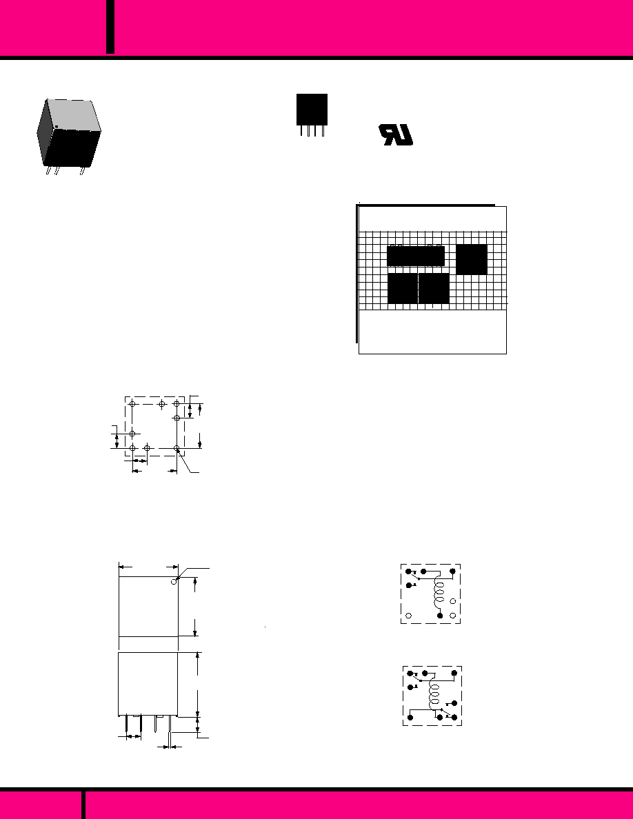
^
v
^
v
^
v
BOTTOM VIEW
.125
(3.18)
.428 Max.
(10.9)
.024 x .012
(0.6 x 0.3 )
.100 Typ
(2.54)
.410 Max.
(10.4)
.410 Max.
(10.4)
WIRING DIAGRAM
OUTLINE DIMENSIONS
Dimensions are in "INCHES" and ( MILLIMETERS )
ACTUAL SIZE
CLASS 7
2 AMP SWITCHING
IN THE WORLDS
SMALLEST PACKAGE.
SPDT, DPDT.
AVAILABLE WITH SPDT OR DPDT BIFURCATED
GOLD CLAD SILVER-PALLADIUM CROSS BAR
CONTACTS- RATED FOR LOW LEVEL TO 2.0 AMP
SWITCHING.
REQUIRES ONLY .155 SQUARE INCH OF
CIRCUIT BOARD SPACE.
TOTAL VOLUME OF LESS THAN A CUBIC
CENTIMETER.
CONFORMS TO FCC PART 68.302. 1500 V PEAK
SURGE RESISTANCE.
CONFORMS TO FCC PART 68.304. 1000 V
DIELECTRIC WITHSTANDING VOLTAGE..
.100
(2.54)
.300
(7.62)
.039 Dia.
(1.0)
.100
(2.54)
.100
(2.54)
.300
(7.62)
0.1 Grid Pattern
PC BOARD PATTERN
Drill Plan (TOP VIEW)
CLASS
7
CLASS
7
DIP
SIZE COMPARISON OF STANDARD
DIP RELAY TO CLASS 7 RELAYS
CLASS
7
TOP VIEW SHOWN AT
ACTUAL SIZE ON A 0.1 GRID
The Class 7 relays can be densely packed
together without magnetic interaction from
adjacent relays.
DPDT
SPDT
C US
UL Recognized
File No. E52197
Recognized Component mark for
Canada and the United States.
The Class 7 Subminiature high
reliability industrial grade relay
has excellent R.F. switching
characteristics.
7
C L A S S
SUBMINIATURE PC MOUNTABLE, EPOXY SEALED
PIERCE THRU
VENT HOLE
PAGE 53
WEBSITE: www.magnecraft.com EMAIL:info@magnecraft.com FAX ON DEMAND 1-800/891-2957 - DOCUMENT 100
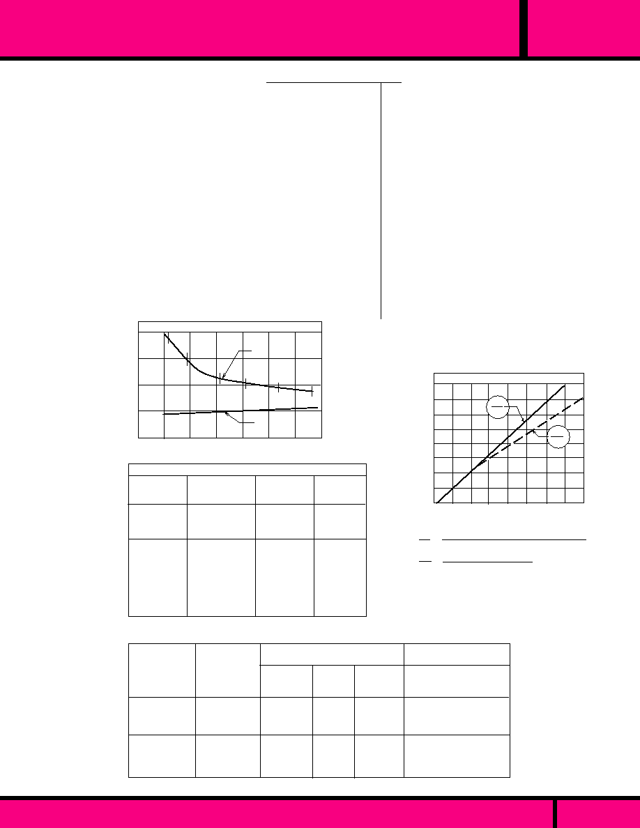
75
440
1550
75
440
1550
W7PCX-1
W7PCX-3
W7PCX-4
W7PCX-5
W7PCX-7
W7PCX-8
SPDT
SPDT
SPDT
DPDT
DPDT
DPDT
5 VDC
12 VDC
24 VDC
5 VDC
12 VDC
24 VDC
Contact
Configuration
Part
Numbers
330
330
370
330
330
370
COIL - Measured at 25�C
Nominal
Resis-
tance
(Ohms)
Nominal
Input
Voltage
Nominal
Power
(mW)
MMS105
MMS112
MMS124
MMS205
MMS212
MMS224
PART NUMBERS SHOWN ALSO AVAILABLE THRU STOCKING DISTRIBUTION.
COMMUNICATIONS
INSTRUMENTS INC / MIDTEX
(CII / MIDTEX)
CROSS REFERENCE
OPERATE TIME
RELEASE TIME
0.3
0.4
0.5
0.6
0.9
COIL APPLIED POWER
0.8
0.7
2
3
0
1
4
OPERATE/RELEASE TIME
(WATTS)
MILLISECONDS
Frequency
VSWR
(MHz)
Insertion Loss
(dB)
Common to
N.O. or N.C.
Contacts
Isolation
(dB)
Common to
N.O. or N.C.
Contacts
R.F. PERFORMANCE
10
50
100
200
300
400
500
65
50
42
35
31
29
28
1.03:1
1.04:1
1.05:1
1.06:1
1.07:1
1.08:1
1.10:1
0.05
0.10
0.30
0.50
0.60
0.65
0.75
N.O. or N.C.
Contacts to
Coil
TEMPERATURE
Operating:
VIBRATION RESISTANCE
Functional:
SHOCK RESISTANCE
Functional
Mechanical:
LIFE
Mechanical:
Electrical:
MISCELLANEOUS
Terminal Finish:
Mounting Position:
Enclosure:
Weight:
-35�C to +70�C
15 g's, 10 to 2000 Hz,
No contact opening > 10 uS
Max. contact chatter
Destructive: 50 g'S.
50g's 6mS half sine
Destructive: 150 g's.
100 Million Operations
100,000 Operations- 2 Amp
24VDC,
1.0 AMP 120VAC (Rated Load).
Terminals are solder Coated
and Epoxy free to provide excellent
solderability. Max. exposure to
soldering temperature is 5 seconds
@ 250�C.
After cleaning process, pierce a
small hole in cover for venting.
Any
UL, 94V-O Plastic, Epoxy Sealed.
2.7 Grams . (.095 oz.)
COIL
Coil Voltages
Pull-in Voltage:
Dropout:
Max. allowed coil voltage:
Nominal Power:
Max. coil dissipation
Coil Resistance range:
CONTACTS
Contact Configuration:
Contact Rating:
Contact Material:
Contact Resistance:
TIMING
Operate Time:
Release Time:
DIELECTRIC STRENGTH
All Mutually Insulated Points:
Surge Test:
Insulation Resistance:
80% of Nominal Voltage or less
10 % of Nominal Voltage or More
120% of nominal voltage, duty cycle: 100%.
327 Milliwatts max., min sensitivity: 200 milliwatts.
0.75 watts.
�
10%
SPDT, DPDT
SPDT: 50uA @ 50mV, 2A , 24VDC, 2A, 120VAC,
DPDT: 50uA @ 50mV, 2A, 24VDC, 0.6A,100VAC,
Gold Clad Silver Palladium.
Initial 50 m
100 Milliohms max @ 6VDC 10 Milliamps.
4.0 mS Max. @ Nominal Voltage. Typ.
5.0 mS Max. @ Nominal Voltage. Typ
500 VAC for 1 Minute, 1 Milliamp max.
leakage, or 600VAC for 1 Second, 1
Milliamp leakage.
Meets FCC 68.302 ( 1500V Surge )
and 68.304 ( 1000V Dielectric ).
500 VDC Exceeds 1000 Megohms.
7
C L A S S
SUBMINIATURE PC MOUNTABLE, EPOXY SEALED
SPECIFICATIONS CLASS 7
WEBSITE: www.magnecraft.com EMAIL:info@magnecraft.com FAX ON DEMAND 1-800/891-2957 - DOCUMENT 100
PAGE 54
0.8
0 . 7
0.6
0.5
0.4
0.3
0.2
0.1
40�
80�
70�
60�
50�
30�
COIL POWER CONSUMPTION
COIL TEMPERATURE RISE
E
2
Rt
E
2
R
20
=
=
COIL VOLTAGE
COIL VOLTAGE
COIL RESIST. VALUE AT 20�C
E
2
R
20
E
2
Rt
20�
10�
0
COIL RESIST. VALUE AFTER TEMP. WAS RAISED
TEMP. RISE �C
After cleaning process, pierce
0.40 (1mm) hole in cover for
venting.

.010
(0.25)
.025 SQ. PINS
(0.64)
.570Max
(14.4)
.010
(0.25)
.025 SQ. PINS
(0.64)
1.10 Max
(27.9)
.175
M a x
(4.45)
DIMENSIONS SHOWN IN "INCHES" AND (MILLIMETERS)
OUTLINE DIMENSIONS
W60HE2S
FIGURE "A"
FIGURE "B"
1.10Max
(27.9)
BOTTOM VIEW
CIRCUIT DIAGRAMS
SPDT
DPDT
ACTUAL SIZE
.105Max
(2.67)
.895 Max
(22.7)
.175 Max
(4.45)
.092
(2.34)
.600 Max
(15.2)
.570Max
(14.4)
.040 DIA
(1.01) TYP.
W60HE2S
.040 DIA
(1.01) TYP.
W60HE1S
TOP VIEW SHOWN AT
ACTUAL SIZE ON A 0.1 GRID
PAGE 55
WEBSITE: www.magnecraft.com EMAIL:info@magnecraft.com FAX ON DEMAND 1-800/891-2957 - DOCUMENT 100
60
C L A S S
MINIATURE P.C. BOARD RELAY MOUNTABLE ON 0.100 GRID
The Class 60 Miniature high
reliability industrial grade
relay has excellent RF
switching characteristics.
CLASS 60
BIFURCATED CROSS BAR CONTACTS
LOW LEVEL SWITCHING TO 2 AMPS
SPDT,DPDT CONTACTS
C US
Recognized Component mark for
Canada and the United States.
UL Recognized
File No. E52197
W60HE1S

PAGE 56
Contact
Configu-
ration
Nominal
Input
Voltage
Resis-
tance
(Ohms)
Pull-in
Power
(mW)
COIL Measured @ 25�C
CROSS REFERENCE
TO
POTTER & BRUMFIELD
PART
NUMBERS
W60HE1S-5DC
W60HE1S-12DC
W60HE1S-24DC
W60HE1S-48DC
W60HE2S-5DC
W60HE2S-12DC
W60HE2S-24DC
W60HE2S-48DC
SPDT
SPDT
SPDT
SPDT
DPDT
DPDT
DPDT
DPDT
5VDC
12VDC
24VDC
48VDC
5VDC
12VDC
24VDC
48VDC
75
440
1550
5250
75
440
1550
5250
200
200
200
200
200
200
200
200
R50E2Y1-5V
R50E2Y1-12V
R50E2Y1-24V
R50E2Y1-48V
R50E2Y2-5V
R50E2Y2-12V
R50E2Y2-24V
R50E2Y2-48V
FIGURE "A"
FIGURE "B"
SPECIFICATIONS CLASS 60
60
C L A S S
MINIATURE P.C. BOARD RELAY MOUNTABLE ON 0.100 GRID
PART NUMBERS SHOWN ALSO AVAILABLE THRU STOCKING DISTRIBUTION.
WEBSITE: www.magnecraft.com EMAIL:info@magnecraft.com FAX ON DEMAND 1-800/891-2957 - DOCUMENT 100
COIL
Pull-in Voltage:
Dropout Voltage:
Max. allowed voltage:
Nominal power:
Max. coil dissipation:
Coil Resistance
CONTACTS
Contact Material:
Contact Resistance:
Contact Rating:
TIMING
Operate Time:
Release Time:
Contact bounce:
DIELECTRIC STRENGTH
All Mutually Insulated Points:
Surge Test:
Insulation Resistance:
TEMPERATURE
Operating:
VIBRATION RESISTANCE
Functional:
SHOCK RESISTANCE
Functional:
Mechanical:
LIFE
Electrical (Rated Load):
Mechanical (No Load):
MISCELLANEOUS
Terminal Finish:
Operating Position:
Enclosure:
Weight:
80% of Nominal Voltage or less
10% of nominal voltage or more
120% of nominal voltage, duty cycle 100%
327mW max. min. sensitivity: 200 mW
0.75 Watt
�
10% Measured @ 25�C
Gold Clad Silver Palladium.
Initial 50 Milliohms @ 6VDC, 10mA
100 Milliohms max., After life: 200 m
Low Level: 50uA- 50mV,
SPDT: 2A-24VDC, 2A-120VAC,
DPDT: 2A-24VDC, 0.6A-100VAC,
4.0 mS Max. @ Nominal Voltage.
10.0 mS Max. @ Nominal Voltage.
2.5 mS operate, 5.0 mS release
500 VAC for 1 Minute, 1 Milliamp max.
leakage, or 600VAC for 1 Second,
1 Milliamp leakage.
Meets FCC 68.302 ( 1500V Surge )
and 68.304 ( 1000V Dielectric ).
500 VDC Exceeds 1000 Megohms.
-35�C to +70�C
15g's, 10 to 2000Hz, (No contact opening
greater than 10
�
S)
50g's, 6mS Max.
Contact Chatter Destructive 50g's.
100,000 Operations Rated Load.
100 Million Operations
Terminals are solder Coated to provide
excellent solderability.
Max. exposure to soldering temperature is
5 seconds @ 250�C.
Any
Plastic.
SPDT-5.5 g's, DPDT- 9 g's approx.

^
v
1
2
3
4
5
CLASS 178
5 AMP AND 12 AMP SPDT CONTACTS.
EPOXY SEALED.
CLASS "B" INSULATION SYSTEM.
.140 Typical
(3.6)
.650 Max
(16.5)
.012
(.30)
.012
(.30)
.039
(.99)
.039
(.99)
.016
(.40)
.890 Max
(22.5)
Dimensions are in "INCH" and ( MILLIMETERS )
.236
(6.0)
.100
(2.54)
.472
(12.0
.480
(12.2)
.079
(2.0)
.090
(2.29)
.044 Dia.
(1.1) (5 Holes)
AC
LOAD
6,000
100,000
100,000
100,000 N.O.
25,000
90,000 N.C.
-
25,000
-
6,000
100,000 N.C*
-
*N.0. CONTACT 25,000 @ 30 VDC
TV-5
TV-3
VA
MOTOR
DC
DC
HP
100,000
100,000
25,000
-
25,000 N.C.
25,000
-
25,000
100,000
-
100,000
OPERATIONS
12A @ 120V
10A @ 125V
10A @ 250V
10A, 1/4 @ 120V
10A, 1/4 @ 250V
10A, 1/4 @ 120V
-
125V
-
12A @ 28V
10A @ 30V
-
12 AMP RELAY STYLE
5 AMP RELAY STYLE
LOAD
LOAD
OPERATIONS
5A @125V
5A @250V
-
1/4 @ 120V
-
1/4 @ 120V
120V
-
125VA @ 120V
5A @ 30V
-
5A,120VAC,pf=0.5
.620Max.
(15.7)
WIRING DIAGRAM
( BOTTOM VIEW )
OUTLINE DIMENSIONS
UL CONTACT LOAD RATINGS
PC BOARD LAYOUT
( BOTTOM VIEW )
SPDT
PAGE 57
WEBSITE: www.magnecraft.com EMAIL:info@magnecraft.com FAX ON DEMAND 1-800/891-2957, Document 100
ACTUAL SIZE
C US
UL Recognized
File No. E164066
Recognized Component mark for
Canada and the United States.
WITHSTANDS THE VAPOR AND SPRAY
CLEANING OF MOST FLUXING SYSTEMS.
TERMINALS ARE SOLDER COATED TO
PROVIDE EXCELLENT SOLDERABILITY.
178
C L A S S
MINIATURE 12 AMP EPOXY SEALED PC BOARD RELAY
PIERCE THRU
VENT HOLE
COIL
Pull-in Voltage:
Dropout Voltage:
Maximum Voltage:
Insulation system:
Coil Resistance:
Duty:
CONTACTS
Contact Configuration:
Contact Material:
Contact Resistance:
Minimum Load:
TIMING
Operate Time:
Release Time:
Bounce Time (typical):
DIELECTRIC STRENGTH
Contacts to Coil:
Across open Contacts:
Insulation Resistance:
TEMPERATURE
Operating:
VIBRATION RESISTANCE
Functional:
SHOCK RESISTANCE
Functional:
LIFE EXPECTANCY
Electrical (Rated Load):
Mechanical (No Load):
MISCELLANEOUS
Terminal Finish:
Operating Position:
Enclosure:
Weight:
75% of Nominal Voltage or less
10% of nominal Voltage or more.
110% of nominal voltage
Class "B" (130�C per UL std. 1446)
�
10% @ 25�C
Continuous
SPDT
Silver Cadmium Oxide
100 Milliohms @ 5VDC & 1 Amp Max.
100mA @ 12VDC
20 mS Max. @ Nominal Voltage.
10mS Max. @ Nominal Voltage.
Operate: 1ms, typ., Release: 4 ms, typ.
1500 VAC for 1 Minute or 1800 VAC 1 Sec
750 VAC for 1 Minute or 800 VAC 1 Sec .
100 Megohms M in. @ 500 VDC
-40�C to +70�C
10 to 55Hz Dual Amplitude -1.5 mm
10g's for 11mS (No Contact Opening >100 uS
100,000
Operations
10 Million Operations
P.C. Terminals are solder Coated and
Epoxy free to provide excellent solderability.
Max. exposure to soldering temperature
is 6 seconds @ 300�C.
Any
Plastic, Epoxy sealed, suitable for
Automatic Circuit Board Processing.
After cleaning process, pierce a
small hole in cover for venting.
0.42 oz. (12) grams approximately.
PAGE 58
WEBSITE: www.magnecraft.com EMAIL:info@magnecraft.com FAX ON DEMAND 1-800/891-2957, Document 100
5 AMPS
5 AMPS
5 AMPS
12 AMPS
12 AMPS
12 AMPS
5VDC
12VDC
24VDC
5VDC
12VDC
24VDC
CONTACT
RATING
NOMINAL
INPUT
VOLTAGE
COIL
Measured @ 25�C
PART NUMBERS
W178RE1-5DC
W178RE1-12DC
W178RE1-24DC
W178URE1-5DC
W178URE1-12DC
W178URE1-24DC
PART NUMBERS SHOWN ALSO AVAILABLE THRU STOCKING DISTRIBUTION.
70
400
1600
70
400
1600
NOMINAL
RESISTANCE
(OHMS)
400
400
400
400
400
400
NOMINAL
POWER
(mW)
T70L5D131-5VDC
T70L5D131-12VDC
T70L5D131-24VDC
T70L5D164-5VDC
T70L5D164-12VDC
T70L5D164-24VDC
RCN1V-5G-DC5V
RCN1V-5G-DC12V
RCN1V-5G-DC24V
RCN1V-10G-DC5V
RCN1V-10G-DC12V
RCN1V-10G-DC24V
IDEC
OMRON
G5L-114P-PS-DC5
G5L-114P-PS-DC12
G5L-114P-PS-DC24
G5LE-114P-PS-DC5
G5LE-114P-PS-DC12
G5LE-114P-PS-DC24
POTTER &
BRUMFIELD
MINIATURE 12 AMP EPOXY SEALED PC BOARD RELAY
C L A S S
SPECIFICATIONS CLASS 178
178
CROSS REFERENCE TO
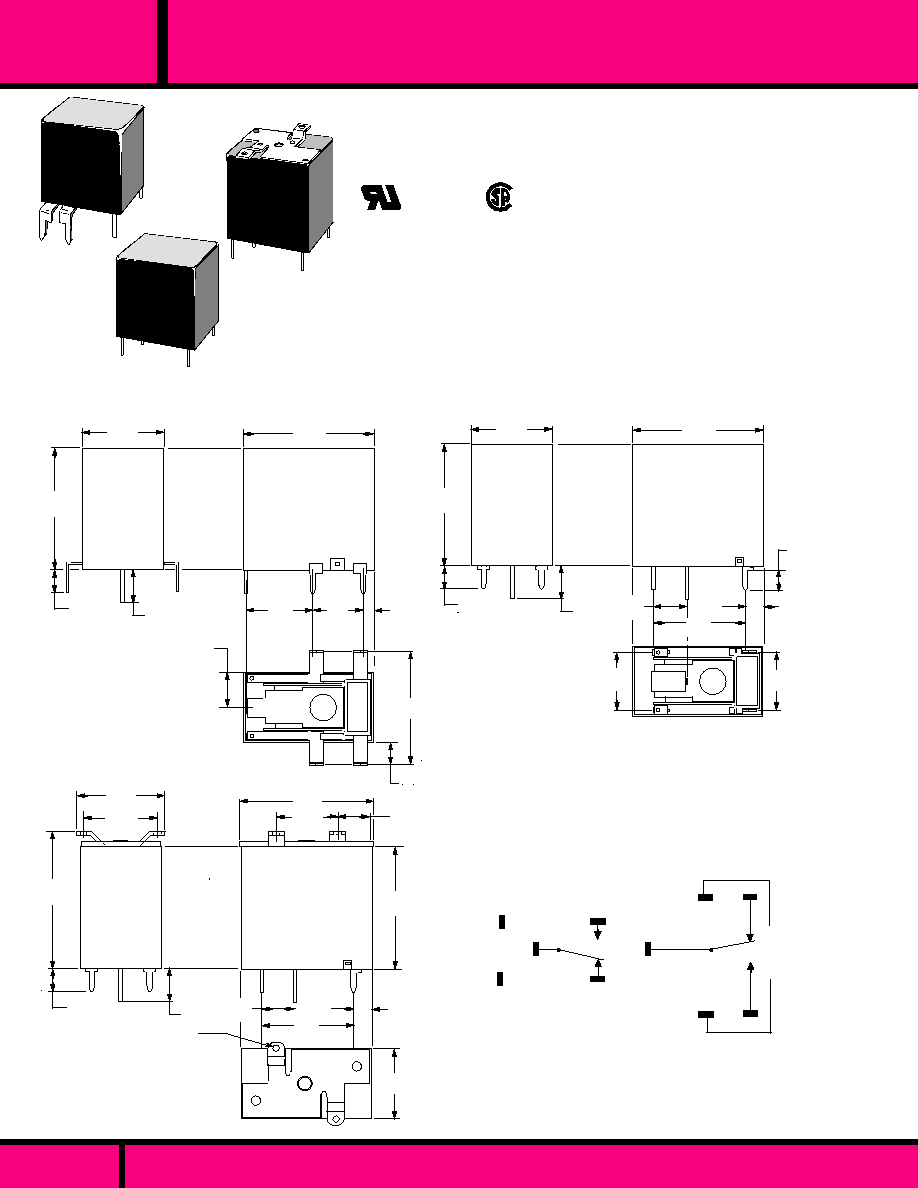
.310
(7.8)
.150
(3.8)
.843
(21.4)
.313
(7.9)
.328
(8.3)
1.14
(29.1)
.687
(17.4)
Max.
.210
(5.3)
.562
(14.2)
1.225
(31.1)
.915
(23.2)
1.34
(34.1)
Max.
4-40 Tapped holes
(2 Req.)
.759Max.
(19.3)
WIRING DIAGRAMS
(BOTTOM VIEW)
STYLE RE1C2
STYLE RE1C1
R1C4
STYLE R1C4
SPDT
SPDT
ALL DIMENSIONS ARE IN INCHES AND MILLIMETERS
Recommended P.C. board holes .067 dia.(1.7)
ALL TERMINALS ARE .056 X .025 (1.42 X 0.64)
OUTLINE DIMENSIONS
(Actual Size)
1.25 Max.
(31.7)
.210
(5.3)
.310
(7.8)
.593
(15.0)
.453
(11.5)
.379
(9.63
.097
(2.5)
1.14 Max.
(29.1)
Max.
.759
(19.3)
.131
(.33)
1.015
(25.7)
1.25 Max.
(31.7)
.310
(7.8)
.150
(3.8)
.843
(21.4)
.546
(13.8
.594
(15.0)
.313
(7.9)
Max.
.759
(19.3)
1.14
(29.1)
Max.
.210
(5.3)
.186 typ.
(4.72)
STYLE RE1C1
STYLE RE1C2
49R1C4-
49RE1C1-
49RE1C2-
WEBSITE: www.magnecraft.com EMAIL:info@magnecraft.com FAX ON DEMAND 1-800/891-2957, DOCUMENT 100
Only 1.1 cubic inches.
Variety of mounting configurations.
Printed circuit terminals.
Tapped mounting holes (49R1C4).
TV 5 rating available.
Standard pilot duty 240 VAC.
Magnetic motor controller rating
1/3 Hp at 120VAC.
CLASS 49 RELAY
LOW LEVEL TO 10 AMPS.
PRINTED CIRCUIT OR
BRACKET MOUNTING.
UL Recognized
File No. E52197
MINIATURE ENCLOSED PC BOARD RELAY - 3 TO 10 AMP
C L A S S
49
PAGE 59

PART NUMBERS
1,500 V rms
500 V rms
1,500 V rms
1000 m
min. @ 500 VDC
-55�C to +85�C
-55�C to +130�C
10 to 55 Hz @ 1.65mm Displacement
10 g's
100 g's
100,000 Operations. .
50,000, 000 Operations.
270�C (518�F) max. for 5 seconds max..
Any.
Dust cover.
42 Grams, 1.5 oz approximately.
DIELECTRIC STRENGTH
Contacts to coil:
Across open contacts:
Coil to frame:
Insulation Resistance:
TEMPERATURE
Operating:
Storage:
VIBRATION RESISTANCE
Functional:
SHOCK RESISTANCE
Functional:
Mechanical:
LIFE
Electrical (Rated Load):
Mechanical No Load):
MISCELLANEOUS
Soldering temperature:
Operating position:
Enclosure:
Weight:
COIL
Pull-in Voltage:
Dropout voltage:
Max. coil voltage
Duty:
Resistance:
CONTACTS
Contact Configuration:
Contact Material:
Contact Resistance:
Contact Rating:
Pilot Duty:
TIMING
Operate:
Release Time:
WEBSITE: www.magnecraft.com EMAIL:info@magnecraft.com FAX ON DEMAND 1-800/891-2957, DOCUMENT 100
VG, VW adj. (DC) = 75% ,
VF, VG adj. (AC) = 80%,of nominal
coil voltage or less.
10% of actual pull-in or more
120% Max.
Continuous
�
10%
SPDT
Silver Cad Oxide (5, 10 Amp), 3 Amp (Silver, Gold
Plated).
100 Milliohms Max. initial Value @ 6 Vdc, 1 Amp
5 and 10 Amp @ 120/240 AC, 3 Amp @ 120 VAC,
28 VDC resistive. Motor load: 1/3 Hp @120VAC,
10 Amp only.
TV 3 SPST-NO, SPST-NC, SPDT
TV 5 SPST-NO, (10 Amp only).
SPST-NO, SPST-NC, SPDT
B300
10 mS typical (25 mS max.)
7mS typical (10 mS max.)
W49RE1C1VG-3DC-SIL
W49RE1C1VG-5DC-SIL
W49RE1C1VG-12DC-SIL
W49RE1C2VF-6DC-SIL
W49RE1C2VF-12DC-SIL
W49RE1C2VF-24DC-SIL
W49RE1C1VG-5DC-SCO
W49RE1C1VG-12DC-SCO
W49RE1C1VG-24DC-SCO
W49RE1C2VF-6DC-SCO
W49RE1C2VF-12DC-SCO
W49RE1C2VF-24DC-SCO
W49RE1C1VW-5DC-SCO
W49RE1C1VW-12DC-SCO
W49RE1C1VW-24DC-SCO
W49R1C4VW-5DC-SCO
W49R1C4VW-24DC-SCO
W49R1C4VG-5DC-SCO
W49R1C4VG-12DC-SCO
60
60
60
56
56
56
90
235
1350
410
1640
6560
3 VDC
5/6 VDC
12 VDC
6 VDC
12 VDC
24 VDC
5/6 VDC
12 VDC
24 VDC
6 VDC
12 VDC
24 VDC
60
60
60
56
56
56
235
1350
5400
410
1640
6560
5/6 VDC
12 VDC
24 VDC
5/6 VDC
12 VDC
135
135
135
60
60
5/6 VDC
24 VDC
135
135
100
600
2400
235
1350
100
2400
PRINTED CIRCUIT BOARD MOUNTING
Nominal
Input
Voltage
Nominal
Resistance
(Ohms)
Pull-in
Power
(mW)
COIL Measured @ 25�C
SPDT, 10 AMP STYLE RE1C1
SOLDER TERMINALS, BRACKET MOUNTING
SPDT, 5 AMP STYLE RE1C1 AND RE1C2
SPDT, 5 AMP- STYLE R1C4
SPDT, 3 AMP STYLE RE1C1
SPDT,10 AMP
PAGE 60
1345-1C-5DC
1345-1C-12DC
1345-1C-24DC
CORNELL
DUBILIER
GUARDIAN
613-6B
613-12B
613-24B
603-6B
603-12B
603-24B
653-3K
653-6K
653-12K
CROSS REFERENCE
C L A S S
SPECIFICATIONS CLASS 49
49
MINIATURE ENCLOSED PC BOARD RELAY - 3 TO 10 AMP
PART NUMBERS SHOWN ALSO AVAILABLE THRU STOCKING DISTRIBUTION.
CONTACT LOAD RATINGS
UL Recognized
File No. E13224
DPDT (5 AMP)
5AMP @ 250VAC RES.
5AMP @ 30VDC
1/4HP @ 250VAC
FIGURE "A"
FIGURE "C"
FIGURE "B"
SPDT (16AMP)
16AMP @ 240VAC RES.
16AMP @ 24VDC
1/2HP @ 250VAC
SPDT (10AMP)
10AMP @ 250VAC RES.
10AMP @ 30VDC
1/3HP @ 250VAC
.811Max.
(20.6)
1.142 Max.
(29.0)
.138
(3.5)Max.
.512 Max.
(13.0)
.300
(7.62)
FIGURE "A"
.795
(20.19)
.400
(10.1)
.300
(7.62)
FIGURE "B"
.795
(20.19)
FIGURE "C"
.039 Dia.
(1.0)
.300
(7.62)
.28
(7.11)
.795
(20.19)
.059
(1.5)
.039 Dia.
(1.0)
.059
(1.5)
.039 Dia.
(1.0)
.059
(1.5)
.400
(10.1)
DRILLING PLAN
(BOTTOM VIEW)
FIGURE "C"
FOOT PRINT FOR
70-478 SOCKET
FIGURE "B"
FOOT PRINT FOR
70-475 SOCKET
FIGURE "A"
FOOT PRINT FOR
70-475 SOCKET
WIRING DIAGRAM
(BOTTOM VIEW)
CLASS 76
5, 10 and 16 AMP. CONTACT RATINGS
EPOXY SEALED, IMMERSION CLEANABLE
MEETS 8mm SPACING 5KV DIELECTRIC
C L A S S
SEE SECTION 10
FOR
MATING SOCKETS
76
MINIATURE EPOXY SEALED PC BOARD POWER RELAY
PAGE 61
WEBSITE: www.magnecraft.com EMAIL:info@magnecraft.com FAX ON DEMAND 1-800/891-2957, DOCUMENT 100
OUTLINE DIMENSIONS
(Actual Size)
All Dimensions are in inches and (millimeters)
PIERCE THRU
VENT HOLE
TEMPERATURE
Operating:
Humidity:
VIBRATION RESISTANCE
Functional:
SHOCK RESISTANCE
Functional:
Mechanical:
LIFE
Electrical (Rated Load):
Mechanical (No Load):
MISCELLANEOUS
Operating position:
Enclosure:
Weight:
COIL
Pull-in Voltage:
Dropout Voltage:
Nominal Power:
Coil Resistance
CONTACTS
Contact Material:
Contact Resistance:
Max.cycle rate:
Minimum Switching Load:
TIMING
Operate Time:
Release Time:
Bounce Time: (Mean Value)
DIELECTRIC STRENGTH
Contacts to Coil:
Across Open Contacts:
Creepage & Clearance
Insulation Resistance:
DC-75% of Nominal Voltage or less
5% of Nominal Voltage or More
600 mW(1 pole) 800 mw (2 pole )Approx..
�
10% Measured @ 20�C
Silver Cadmium Oxide
100 Milliohms Max.
30 Operations per Minute @ rated Load.
10 VDC @ 10 mA
15 mS Max. @ Nominal Voltage.
10 mS Max. @ Nominal Voltage.
1.2 mS Approx.
5000 V rms, for 1 Minute
1000 V rms, for 1 Minute
8 Millimeters Min. Coil & Contacts
500VDC Exceeds 100 Megohms
PART NUMBERS SHOWN ALSO AVAILABLE THRU STOCKING DISTRIBUTION.
10 AMP
10 AMP
10 AMP
10 AMP
10 AMP
5 AMP
5 AMP
5 AMP
5 AMP
16 AMP
16 AMP
16 AMP
16 AMP
16 AMP
PART NUMBERS
FIG.
COIL
Measured @ 20�C
W76EURCPCX-14
W76EURCPCX-15
W76EURCPCX-16
W76EURCPCX-17
W76EURCPCX-18
W76EURCPCX-61
W76EURCPCX-62
W76EURCPCX-63
W76EURCPCX-64
W76EURCPCX-146
W76EURCPCX-147
W76EURCPCX-148
W76EURCPCX-149
W76EURCPCX-150
5 VDC
6 VDC
12 VDC
24 VDC
48 VDC
5 VDC
6 VDC
12 VDC
24 VDC
5 VDC
6 VDC
12 VDC
24 VDC
48 VDC
47
68
275
1,100
4,170
47
68
275
1,100
47
68
275
1,100
4,170
SPDT
SPDT
SPDT
SPDT
SPDT
DPDT
DPDT
DPDT
DPDT
SPDT
SPDT
SPDT
SPDT
SPDT
NOMINAL
INPUT
VOLTAGE
CONTACT
CONFIGU-
RATION
CONTACT
RATING
"C"
"C"
"C"
"C"
"C"
"A"
"A"
"A"
"A"
"B"
"B"
"B"
"B"
"B"
Nominal
Resistance
(Ohms)
RKS-5DG-05
RKS-5DG-06
RKS-5DG-12
RKS-5DG-24
RKS-5DG-48
RKS-11DG-05
RKS-11DG-06
RKS-11DG-12
RKS-11DG-24
RKS-5DW-05
RKS-5DW-06
RKS-5DW-12
RKS-5DW-24
RKS-5DW-48
POTTER &
BRUMFIELD
G2R-14-DC5
G2R-14-DC6
G2R-14-DC12
G2R-14-DC24
G2R-14-DC48
G2R-24-DC5
G2R-24-DC6
G2R-24-DC12
G2R-24-DC24
G2R-1-E-DC5
G2R-1-E-DC6
G2R-1-E-DC12
G2R-1-E-DC24
G2R-1-E-DC48
CROSS REFERENCE
JW1FEN-DC5V
JW1FEN-DC6V
JW1FEN-DC12V
JW1FEN-DC24V
JW1FEN-DC48V
JW2EN-DC5V
JW2EN-DC6V
JW2EN-DC12V
JW2EN-DC24V
C L A S S
MINIATURE EPOXY SEALED PC BOARD POWER RELAY
-30�C to +70�C
45 - 85% RH
10 to 55 Hz Dual Amplitude 1.5mm
10 g's Min
100 g Min.
100,000 Operations min.
10,000,000 Operations min.
Any
Epoxy sealed for protection during
automatic wave soldering & cleaning
process. After cleaning process, pierce
a small hole in cover for venting.
13 Grams approx
.
OMRON
AROMAT
SPECIFICATIONS CLASS 76
WEBSITE: www.magnecraft.com EMAIL:info@magnecraft.com FAX ON DEMAND 1-800/891-2957, DOCUMENT 100
PAGE 62
76
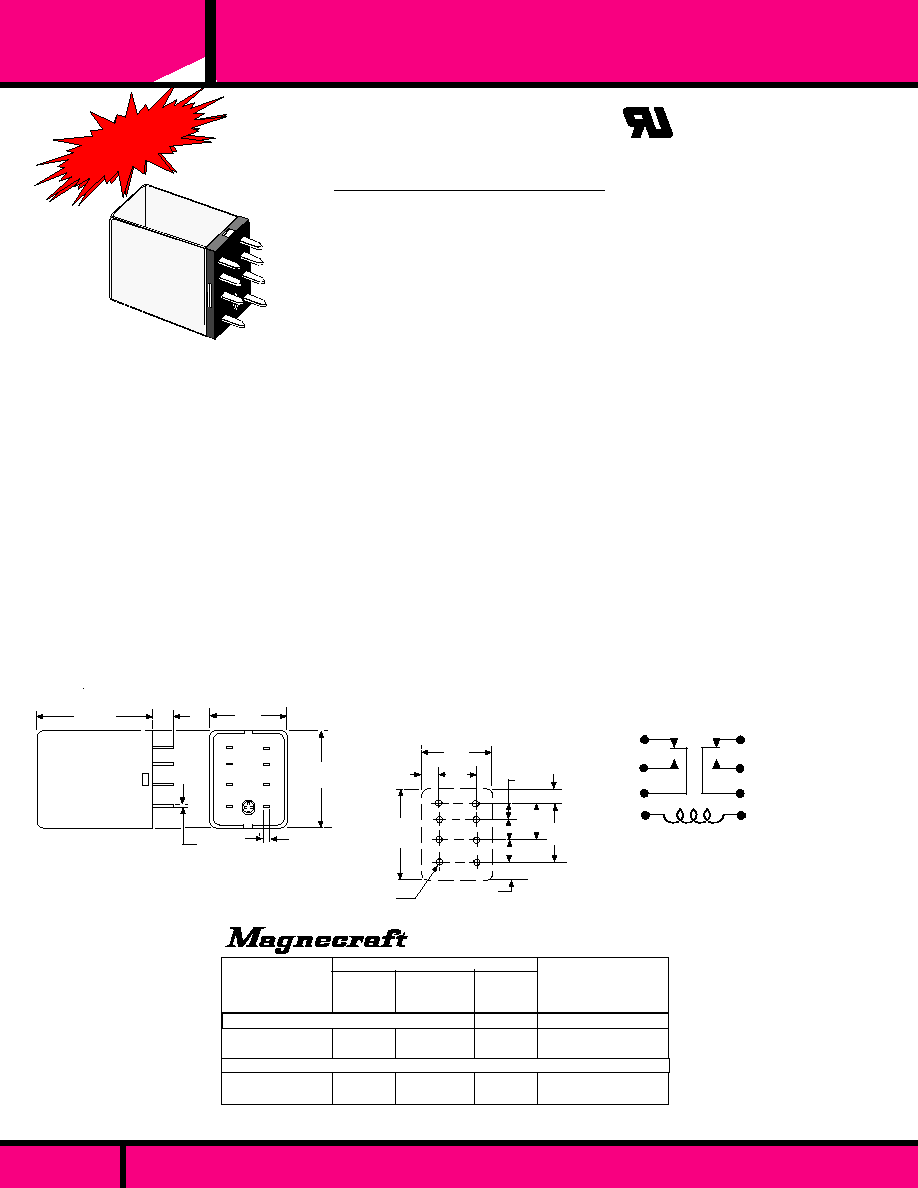
COIL
Pull-in Voltage:
Dropout:
Max. Voltage:
Coil Resistance:
Duty:
CONTACTS
Contact Configurations:
Contact Material:
Contact Resistance:
Contact Rating:
TIMING
Operate Time:
Release Time:
DIELECTRIC STRENGTH
Coil to Frame:
Across Open Contacts:
Contact to Frame:
Insulation Resistance:
TEMPERATURE
Ambient Temperature:
LIFE EXPECTANCY
Mechanical
Electrical (rated Load):
MISCELLANEOUS
Operating Position:
Insulating Material:
Enclosure:
Weight:
75% of Nominal Voltage or less for AC or DC Coils
DC -10% min.or more.
110%
�
10% @ 25�C
Continuous
DPDT
Silver Cadmium Oxide, .93 Dia. (2.36).
100 Milliohms Max.
UL RATED - 5 Amperers @ 120 VAC resistive
NOT UL RATED - 30 VDC resistive, 3 Amperes Inductive, 1/8 Hp @ 120 VAC.
20mS Max. AC, 15 mS Max. DC @ Nominal Voltage, 25�C.
20mS Max. AC, 15 mS Max. DC @ Nominal Voltage, 25�C.
1500 V rms
500 V rms
1500 V rms
1500 Megohms Min.
-45�C to + 70�C @ Rated Operation.
AC operated Device in excess of 50 million operations
DC operated devices, in excess of 100 million operations.
100,000 Operations Min. (at rated Resistive load).
Any.
Molded parts are diallyl phthalate for higher arc resistance.
Clear heat resistant Polycarbonate Dust Cover.
Approximately 3/4 oz.
1
2
3
4
5
6
7
8
9
11
10
.905 Max.
(23)
.020 Max.
(.5) Ref.
.052 Typ.
(1.31)
.551
(14)
.123
(3.1)
.350
(8.9)
.728 Ref
(18.5)
.905 Ref
(23)
.157
(4)
.197(5)
.197(5)
.354
(9)
.189
(4.8)
CIRCUIT DIAGRAM
Nominal
Input
Voltage
W1330P-2C-24A
W1330P-2C-120A
W1335P-2C-12D
W1335P-2C-24D
24 VAC
120 VAC
12 VDC
24 VDC
DC OPERATED COILS
Coil Measured at 25�C
Nominal
Resistance
(Ohms)
Nominal
Power
1.075 Max.
(27.3)
.200
Max.
.728 Max.
(18.5)
.067 Dia.
(1.7)
8 PL
.231 Ref
(5.9)
DC OPERATED COILS
AC OPERATED COILS
245
5400
125
500
1.2 VA
1.2 VA
1.2 W
1.2 W
CROSS REFERENCE
TO
GUARDIAN
PART NUMBERS
P.C. BOARD LAYOUT
SPECIFICATIONS CLASS 1330 & 1335
NEW!
NEW!
NEW!
NEW!
NEW!
MANUFACTURED UNDER
QUALITY SYSTEM
ISO 9002 & QS 9000
PAGE 63
WEBSITE: www.magnecraft.com EMAIL:info@magnecraft.com FAX ON DEMAND 1-800/891-2957 - DOCUMENT 100
1330 & 1335
C L A S S
ENCLOSED MINIATURE 2 POLE RELAY
UL Recognized
File No. E52197
C US
Recognized Component mark for
Canadian and the United States.
PENDING
SPACE SAVING DPDT, P.C. BOARD RELAY
AC OR DC OPERATED COIL.
RATED: 5 AMPS RESISTIVE, 3 AMPS INDUCTIVE
1330P-2C-24A
1330P-2C-120A
1335P-2C-12D
1335P-2C-24D
PART NUMBERS SHOWN ALSO AVAILABLE THRU STOCKING DISTRIBUTION.

3
S E C T I O N
3
REED RELAYS
FOR
PRINTED CIRCUIT BOARD
APPLICATIONS
4 VA TO 100 VA.
COAXIAL RELAYS
FOR R.F. SWITCHING.
Page 64
H W L
H W L
RELAY SERIES
COIL DATA
GENERAL DATA
DIMENSIONS:
INSULATION
CHARACTERISTICS
DIELECTRIC STRENGTH:
.355 X PG.39 X 1.15
.290 X .280 X .750
UP
SPST-NO, or NC, SPDT, DPDT
MAX. SWITCHING
0.5 AMPS or 100 VDC
@ 4VA -10VA
MAX.CARRY LOAD 1.5 AMPS
.338 X .393 X .750 (DPDT)
.275 X .300 X .750
H W L
.355 X .400 to .900 X 1.15
H W L
SPST-NO, SPST-NC
MAX. SWITCHING
0.5 AMPS or 200 VDC
@ 10 VA
MAX.CARRY LOAD 1.5 AMPS
MOUNTING POSITION:
ANY
SPDT
DPDT
SOCKET AVAILABLE
SEE SECTION 10
EPOXY MOLDED
CONSTRUCTION.
STANDARD 0.1 GRID
SPACING.
AVAILABLE WITH OR
WITHOUT SUPPRESSION
DIODE ACROSS COIL..
.
UP
SPDT - EPOXY MOLDED
CONSTRUCTION. DPDT -
ENCAPSULATED CONSTRUC-
TION.
STANDARD 0.1 GRID
SPACING.
AVAILABLE WITH SUPPRES-
SION DIODE ACROSS COIL.
CLASS 107 PROVIDES
4 HOOK- UP PINS TO COIL..
ELECTROSTATIC SHIELD
OPTIONAL.
ENCAPSULATED
CONSTRUCTION OR EPOXY
MOLDED WITH SIDE
TERMINALS
STANDARD 0.1 GRID OR
OPTIONAL 0.15 SPACING.
NON LATCHING SINGLE
COIL OR SINGLE & DUAL
COIL MAGNETIC LATCHING.
ELECTROSTATIC SHIELD
OPTIONAL.
SPST-NO, DPST-N0
MAX. SWITCHING
2.0 AMPS or 500 VDC
@ 50 VA
MAX.CARRY LOAD 3.0 AMPS
FEATURES
5, 12, 24 VDC
270 mW Max.
DC - VOLTAGE RANGE:
NOMINAL POWER:
ENCAPSULATED
CONSTRUCTION.
STANDARD 0.1 GRID OR
OPTIONAL 0.15 SPACING.
POSITION SENSITIVE
VERTICAL MOUNTING.
EXCELLENT FOR LOW
LEVEL SWITCHING.
ELECTROSTATIC SHIELD
OPTIONAL.
ANY
ANY
VERTICAL
�
15�
- 40� C to + 85� C
1 MILLISECONDS
1 MILLISECONDS
100 MILLION OPERATIONS
50 MILLION OPERATIONS
- 40� C to + 85� C
1 MILLISECONDS
1 MILLISECONDS
100 MILLION OPERATIONS
50 MILLION OPERATIONS
- 40� C to + 85� C
1 MILLISECONDS
1 MILLISECONDS
100 MILLION OPERATIONS
50 MILLION OPERATIONS
5, 12, 24 VDC
380 mW Max.
5, 12, 24 VDC
625 mW Max.
- 37� C to + 85� C
2 MILLISECONDS
2 MILLISECONDS
100 MILLION OPERATIONS
40 MILLION OPERATIONS
1000 V rms
500 VDC
1000 V rms
1500 V rms
5, 12, 24 VDC
650 mW Max.
RHODIUM
100 MILLIOHMS (INITIAL)
RHODIUM
100 MILLIOHMS (INITIAL)
AMBIENT TEMPERATURE
OPERATIONAL:
TIMING VALUES
MAX. OPERATE:
MAX. RELEASE:
LIFE
MECHANICAL:
ELECTRICAL:
WEBSITE: www.magnecraft.com EMAIL:info@magnecraft.com FAX ON DEMAND 1-800/891-2957, DOCUMENT 100
PAGE 65
RHODIUM
100 MILLIOHMS (INITIAL)
MERCURY (Hg)
50 MILLIOHMS (INITIAL)
131 MERCURY
"SIP"
101
"DIP"
PAGE NUMBER:
PAGE 70
PAGE 68, 69
PAGE 71 thru 75
APPLICATION DATA:
MINIATURE REED SPECIFICATIONS:
PAGE 77
PAGE 78
CONTACT CONFIGURATION:
MAXIMUM CONTACT RATING:
CONTACT MATERIAL:
CONTACT RESISTANCE:
1 to 3PST-NO,
MAX. SWITCHING
0.5 AMPS or 200 VDC
@ 10 VA
MAX.CARRY LOAD 2.0 AMPS
NEW!
DPDT DIP
PRINTED CIRCUIT BOARD REED RELAYS
PAGE 76
Magnecraft
Struthers-Dunn

WEBSITE: www.magnecraft.com EMAIL:info@magnecraft.com FAX ON DEMAND 1-800/891-2957, DOCUMENT 100
PAGE 66
193
104
MR-Y
134 MERCURY
UP
ANY
ANY
500 V rms
RHODIUM
200 MILLIOHMS (INITIAL)
500 V rms
.355 X .5 to .7 X 1.15
5, 12, 24 VDC
626 mW Max.
SPDT, DPDT
MAX SWITCHING
0.25 AMPS or 100VDC
@ 4 VA
MAX.CARRY LOAD 0.5 AMP
355 X .5 to .5 X 1.15
SPDT, DPDT
MAX SWITCHING
1.0 AMPS or 500VDC
@ 50 VA
MAX.CARRY LOAD 2.0 AMP.
1000 V rms
5, 12, 24 VDC
620 mW Max.
MERCURY
100 MILLIOHMS (INITIAL)
DUST COVER STANDARD.
ENCAPSULATED CON-
STRUCTION OPTIONAL
STANDARD 0.1 GRID
OR OPTIONAL 0.15
SPACING AVAILABLE.
POSITION SENSITIVE.
VERTICAL MOUNTED.
DUST COVER STANDARD.
ENCAPSULATED CONSTRUC-
TION OPTIONAL
STANDARD 0.1 GRID OR
OPTIONAL 0.15 GRID
SPACING AVAILABLE.
DUST COVER STANDARD.
ENCAPSULATED CON-
STRUCTION OPTIONAL
STANDARD 0.1 GRID OR
OPTIONAL 0.15 GRID
SPACING.
UP TO 4PDT OR 6PST
CONTACT ARRANGE-
MENTS.
RHODIUM
200 MILLIOHMS (INITIAL)
500 V rms
5, 12, 24 VDC
1030 mW Max.
.355 X .4 to .9 X 1.15
EPOXY MOLDED.
STANDARD 0.1 GRID OR
OPTIONAL 0.15 GRID
SPACING AVAILABLE.
MAGNETIC SHIELDING.
END TERMINALS.
TTL COMPATIBLE.
5, 12, 24 VDC
450 mW Max.
.312 X 0.4 X .950
PAGE 83, 84
MRR & RR
.655 X 1.875
ANY
1 & 2PST-NO or
NC SPDT, DPDT
MAX SWITCHING
0.5 AMPS or 200VDC
@ 10 VA
MAX.CARRY LOAD 1.5 AMP
1 to 4PDT, 1 to 6PST
MAX SWITCHING
0.5 AMPS or 200VDC
@ 10 VA
MAX.CARRY LOAD 2.0 AMP
1 to 12PST-NO 0r NC
MAX SWITCHING
0.5 AMP or 200VDC
@ 10 VA
MAX.CARRY LOAD 1.5 AMPS
RHODIUM
200 MILLIOHMS (INITIAL)
RHODIUM
200 MILLIOHMS (INITIAL)
500 V rms
6 to 48 VDC
400 mW Max.
-40 �C to + 85 �C
5 MILLISECONDS
5 MILLISECONDS
200 MILLION OPERATIONS
10 MILLION OPERATIONS
H W L H W L H W L H W L
-40 �C to + 85 �C
1 MILLISECONDS
1.5 MILLISECONDS
100 MILLION OPERATIONS
50 MILLION OPERATIONS
-37 �C to + 85 �C
2 MILLISECONDS
3 MILLISECONDS
100 MILLION OPERATIONS
40 MILLION OPERATIONS
VERTICAL
�
15�
PAGE 80
PAGE 81, 82
PAGE 85, 86
-40�C to + 85 �C
1 MILLISECONDS
1 MILLISECONDS
100 MILLION OPERATIONS
50 MILLION OPERATIONS
ANY
PAGE 79
-40�C to + 85 �C
1 MILLISECONDS
1 MILLISECONDS
100 MILLION OPERATIONS
50 MILLION OPERATIONS
EPOXY MOLDED AXIAL
LEAD REED RELAY
EXTERNAL MAGNETIC
SHIELDING FIXED TO
BODY.
SOLID LEADS
DIAMETER
Magnecraft
Struthers-Dunn
MINIATURE REED RELAYS

DC - VOLTAGE RANGE:
NOMINAL POWER:
FEATURES
COIL DATA
GENERAL DATA
DIELECTRIC STRENGTH:
PAGE NUMBER
MOUNTING POSITION
CONTACT DATA
INSULATION
CHARACTERISTICS
AMBIENT TEMPERATURE
OPERATIONAL:
TIMING VALUES
MAX. OPERATE:
MAX. RELEASE:
LIFE
MECHANICAL:
ELECTRICAL:
DIMENSIONS
CONTACT CONFIGURATION:
MAXIMUM CONTACT RATING:
CONTACT MATERIAL:
CONTACT RESISTANCE:
WEBSITE: www.magnecraft.com EMAIL:info@magnecraft.com FAX ON DEMAND 1-800/891-2957, DOCUMENT 100
PAGE 67
RELAY SERIES
12, 24 VDC
800 mW Max
1500 V rms
RHODIUM
200 MILLIOHMS (INITIAL)
SPST-NO
MAX SWITCHING
1.0 or 3.0 AMPS or 250VDC
@ 15 or 100 VA
MAX.CARRY LOAD 2 or 3.5 AMPS
OPEN END CONSTRUCTION
DRY REED
SWITCHING UP TO 3.0
AMPS @ 250 VDC.
METAL COVER/SHIELD
STANDARD
0.2 GRID SPACING.
102
-40 �C to + 85 �C
6 MILLISECONDS
6 MILLISECONDS
200 MILLION OPERATIONS
10 MILLION OPERATIONS
.641 X 0.74 X 2.50
6 to 48 VDC
700 mW Max.
1500 V rms
RHODIUM
200 MILLIOHMS (INITIAL)
See Catalog Page
MAX SWITCHING
0.5 or 1.0 AMP or 250VDC
@ 10 or 15 VA
OPEN END CONSTRUCTION
WITH METAL COVER
MAGNETIC SHIELDING
0.2 GRID SPACING
SINGLE PIECE GLASS FILLED
BOBBIN AND TERMINALSUPPORT
VARIOUS CONTACT ARRANGE-
MENTS.
RRN
PAGE 87, 88
PAGE 89
0.65 X 0.76 X 2.67
ANY
ANY
H W L H W L
-40 �C to + 85 �C
5 MILLISECONDS
6 MILLISECONDS
100 MILLION OPERATIONS
20 MILLION OPERATIONS
120 COAXIAL
150 WATT SWITCHING
UP TO 470 MHz.
RG58C/U CABLE, 12"
LONG STANDARD.
50 OHM IMPEDANCE
1 FORM C (DPDT)
R.F. SWITCHING
CONTACTS.
SPDT
150 Watts up to 470 MHz
SILVER ALLOY
GOLD FLASHED
50 MILLIOHMS (INITIAL)
1,500 V rms
12 VDC
- 55� C to + 65� C
15 MILLISECONDS
7 MILLISECONDS
100,000 OPERATIONS
5 MILLION OPERATIONS
H W L
.1.62 X.703 X 1.73
ANY
PAGE 90
1.44 Watts
Magnecraft
Struthers-Dunn
P.C. BOARD REED RELAYS & COAXIAL
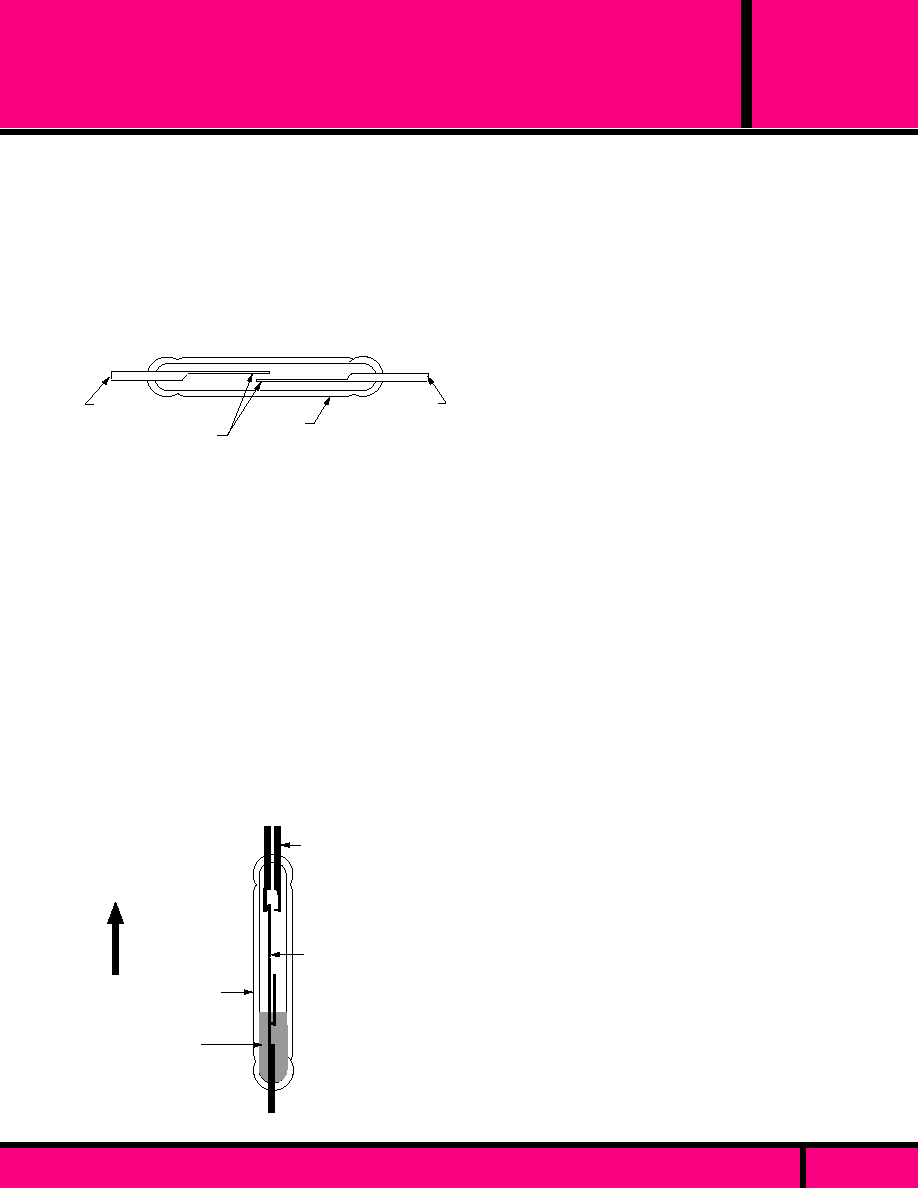
APPLICATION DATA
12345
12345
12345
12345
12345
12345
12345
12345
12345
12345
12345
12345
12345
12345
12345
12345
12345
12345
12345
12345
12345
12345
12345
12345
12345
12345
123456
123456
123456
123456
123456
123456
123456
123456
123456
123456
123456
123456
MERCURY-WETTED CONTACT RELAYS. ( CONTINUED)
Mercury wetted contacts are fast in operation and have relatively good load
carrying capacity and long life. The mercury films are reestablished at each
contact closure and contact erosion is eliminated.. The mercury films are
stretchable, there is no contact bounce and because it is a mercury contact, the
contact resistance is very low and ideal for low level switching applications.
The disadvantages of this type of reed relay are the freezing point of mercury
(-38�C), poor resistance to shock and vibration and the need to mount the relay in
a near vertical position.
These relays are used for a variety of switching applications such as found in
computers, business machines, machine tool control systems, and laboratory
instruments.
CONTACT COMBINATIONS.
The switches used in dry reed relays provide SPST-NO, SPST-NC, SPDT contact
combinations.
The SPST-NO corresponds with the basic switch capsule design (Fig.1).
The SPST-NC results from a combination of the SPST-NO switch and
a permanent magnet strong enough to pull the contacts closed but able to open
when coil voltage is applied to the relay coil.
In typical true SPDT designs, the armature is mechanically tensioned
against the normally closed contact, and is moved to the normally open contact
upon application of a magnetic field. The SPDT contact combination can also be
achieved by joining a SPST-NO switch with an appropriately adjusted SPST-NC
switch, and jumping one side of both switches together to form the movable contact
system.
Latching contacts, defined as contacts which remain in the position to
which they were driven, and staying in that position when coil power is removed
from the relay coil.
Latching switches are manufactured by using a SPST-NO contact, and biasing it
with a permanent magnetic that is strong enough to hold the contacts closed,
but not strong enough to hold the contact closed when coil power is applied to the
coil. The switching process is than reversed by simply reversing the relay coil
polarity to close the switch.
MAGNETIC FIELDS
Reed relays in general can be characterized as susceptible to the influences of
external magnetic fields. It is important to keep reed relays at a proper distance
from each other because of the possibility of magnetic-interaction between them.
Proper magnetic shielding must be used to contain stray magnetic fields. When
installing reed relays into equipment, one should be aware of the devices within
that equipment which can produce magnetic fields. The relays being installed into
that equipment should be positioned as far away as possible from any stray
magnetic fields and should be shielded to prevent false operations.
ELECTRICAL CHARACTERISTICS
SENSITIVITY: The input power required to operate dry reed relays is determined
by the sensitivity of the particular reed switch used, by the number of switches
operated by the coil, by the permanent magnet biasing (if used), and the efficiency
of the coil and the effectiveness of its coupling to the blades. Minimum input
required to effect closure ranges from the very low milliwatt level for a single
sensitive capsule to several watts for multipole relays.
OPERATE TIME: The coil time constant, overdrive on the coil, and the character-
istics of the reed switch determine operate time. With the maximum overdrive
voltage applied to the coil, reed relays will operate in approximately the 200
microsecond range. When driven at rated coil voltage, usually the relays will
operate at about one millisecond.
RELEASE TIME: With the coil unsuppressed, dry reed switch contacts release
in a fraction of a millisecond. SPST-NO contacts will open in as little as 50
microseconds. Magnetically biased SPST-NC and SPDT switches reclose from
100 microseconds to 1 millisecond respectively.
UP
OPERATING
POSITION
Mercury
pool
Glass
Capsule
Movable
contact blade
Supporting
Leadwire
Figure 2. Miniature Mercury-wetted contact switch (SPDT)
REED
RELAYS
PAGE 68
WEBSITE: www.magnecraft.com EMAIL:info@magnecraft.com FAX ON DEMAND 1-800/891-2957, DOCUMENT 100
HOW REED RELAYS WORK
The term reed relay covers dry reed relays and mercury-wetted
contact relays, all of which use hermetically sealed reed switches.
In both types, the reeds (thin, flat blades) serve multiple functions -
as conductor, contacts, springs, and magnetic armatures.
DRY REED RELAYS
Dry reed relays have become an important factor in the relay field.
They have the advantage of being hermetically sealed and resistant
to atmospheric contamination. They have fast operate and release
times and when operated within their rated contact loads, have very
long life. A typical dry reed switch capsule is shown in Figure 1.
12345678901234567890123456
12345678901234567890123456
12345678901234567890123456
12345678901234567890123456
12345678901234567890123456
12345678901234567890123456
123456
123456
123456
123456
123456
123456
123456
123456
123456
123456
123456
123456
Normally
Open
Contacts
Glass
Capsule
Supporting
Terminal
Supporting
Terminal
Figure 1. Construction of Switch Capsule of Typical Dry Reed switch (SPST-NO)
In the basic SPST-NO design, two opposing blades are sealed into a
narrow glass capsule and overlapped at their free ends. The contact
area is plated typically with rhodium to produce a low contact resistance
when contacts are drawn together. The capsule is made of glass and
filled with a dry inert gas and then sealed. The capsule is surrounded by
an electromagnetic coil. When the coil is energized, the normally open
contacts are brought together; when the coil voltage is removed, the
blades separate by their own spring tension. Some reeds contain
permanent magnets for magnetic biasing to achieve normally closed
contacts (SPST-NC) or SPDT contact combinations. The current rating,
which is dependent upon the size of the blade and the type and amount
of plating, may range from low level to 1 amp. Effective contact protection
is essential when switching loads other then dry resistive loads.
MERCURY-WETTED CONTACT RELAYS.
Mercury wetted contacts consist of a glass-encapsulated reed with its
base immersed in a pool of mercury and the other end capable of moving
between one or two stationary contacts. The mercury flows up the reed by
capillary action and wets the contact surfaces of the moving end of the
reed as well as the contact surfaces of the stationary contacts. A mercury
to mercury contact is maintained in the closed position. The capsule is
surrounded by an electromagnetic coil and operates in the same manner
as a dry reed.

APPLICATION DATA
REED
RELAYS
ELECTRICAL CHARACTERISTICS (Continued)
RELEASE TIME (Continued)
If the relay coil is suppressed, release times are increased. Diode suppres-
sion can delay release times for several milliseconds, depending on coil
characteristics, coil voltage, and reed release characteristics.
CONTACT BOUNCE
Dry reed contacts bounce on closure as with any other hard contact relay.
The duration of bounce on a Dry reed switch is typically very short, and is
in part dependent on drive level. In some of the faster devices, the sum of
the operate time and bounce is relatively constant. As drive is increased, the
operate time decreases with bounce time increasing.
The normally closed contacts of a SPDT switch bounce more then the
normally open contacts. Magnetically biased SPST-NC contacts exhibit
essentially the same bounce characteristics as SPST-NO switches.
CONTACT RESISTANCE
The reeds (blades) in a dry reed switch are made of magnetic material
which has a high volume resistivity, terminal-to-terminal resistance is
somewhat higher than in some other types of relays. Typical specification
limits for initial resistance of a SPST-NO reed relay is 0.200 ohms max
(200 milliohms).
INSULATION RESISTANCE
A dry reed switch made in a properly controlled internal atmosphere will
have an insulation resistance of 10
12
to 10
13
ohms or greater. When it is
assembled into a relay, parallel insulation paths reduce this to typical values
of 10
9
ohms. Depending on the particular manner of relay construction,
exposure to high humidity or contaminating environments can appreciably
lower final insulation resistance.
CAPACITANCE.
Reed capsules typically have low terminal-to-terminal capacitance.
However, in the typicall relay structure where the switch is surrounded by a
coil, capacitance from each reed to the coil act to increase capacitance
many times. If the increased capacitance is objectionable, it can be
reduced by placing a grounded electrostatic shield between the switch and
coil.
DIELECTRIC WITHSTAND VOLTAGE
With the exception of the High-Voltage dry reed switches ( capsules that
are pressurized or evacuated), the dielectric strength limitation of relays is
determined by the ampere turn sensitivity of the switches used. A typical
limit is 200 VAC. The dielectric withstand voltage between switch and coil
terminals is usually 500 VAC.
THERMAL EMF
Since thermally generated voltages result from thermal gradients within the
relay assembly, relays built to minimize this effect often use sensitive
switches to reduce required coil power, and thermally conductive materials
to reduce temperature gradients. Latching relays, which may be operated
by a short duration pulse, are often used if the operational rate is not
changed for longer periods of time because coil power is not required to
keep the relay in the on or off position after the initial turn on or turn off
pulse.
NOISE
Noise is defined as a voltage appearing between terminals of a switch for a
few milliseconds following closure of the contacts. It occurs because the
reeds (blades) are moving in a magnetic field and because voltages are
produced within them by magnetostrictive effects. From an application
standpoint, noise is important if the signal switched by the reed is to be used
within a few milliseconds immediately following closure of the contacts.
When noise is critical in an application, a peak-to-peak limit must be
established by measurement techniques, including filters which must be
specified for that particular switching application.
ENVIRONMENTAL CHARACTERISTICS
Reed relays are used in essentially the same environments as other types of
relays. Factors influencing their ability to function would be
temperature extremes beyond specified limits
VIBRATION
The reed switch structure, with so few elements free to move, has a better
defined response to vibration than other relay types. With vibration inputs
reasonably separated from the resonant frequency, the reed relay will
withstand relatively high inputs, 20 g's or more. At resonance of the reeds,
the typical device can fail at very low input levels. Typical resonance
frequency is 2000 hz.
SHOCK
Dry reed relays will withstand relatively high levels of shock. SPST-NO
contacts are usually rated to pass 30 to 50 g's, 11 milliseconds, half sign
wave shock, without false operation of contacts. Switches exposed to a
magnetic field that keep the contacts in a closed position, such as in the
biased latching form, demonstrate somewhat lower resistance to shock.
Normally closed contacts of mechanically biased SPDT switches may also
fail at lower shock levels.
TEMPERATURE
Differential expansion or contraction of reed switches and materials used in
relay assemblies can lead to fracture of the switches. Reed relays are
capable of withstanding temperature cycling or temperature shock over a
range of at least -50�C to + 100�C. These limits should be applied to the
application to prevent switch failure.
CONTACT PROTECTION
Tungsten lamp, inductive and capacitive discharge load are extremely
detrimental to reed switches and reduce life considerably. Illustrated below
are typical suppression circuits which are necessary for maximum contact
life.
DC inductive loads call for either a diode or a thyristor to be placed across
the load. These circuits are necessary to protect the contacts
when inductive loads are to be switched in a circuit, as shown in Figure 4.
FIGURE 4
Input
Input
Initial turn-on current is generally 10 times higher than the rated
operating current of the lamp. A current limiting resistor in series with
the load, or a bleeder resistor across the contacts will suppress the
inrush current. Thesesame circuits can be used with capacitive loads,
as shown in Figure 3.
R
R
Input
Input
FIGURE 3
WEBSITE: www.magnecraft.com EMAIL:info@magnecraft.com FAX ON DEMAND 1-800/891-2957, DOCUMENT 100
PAGE 69
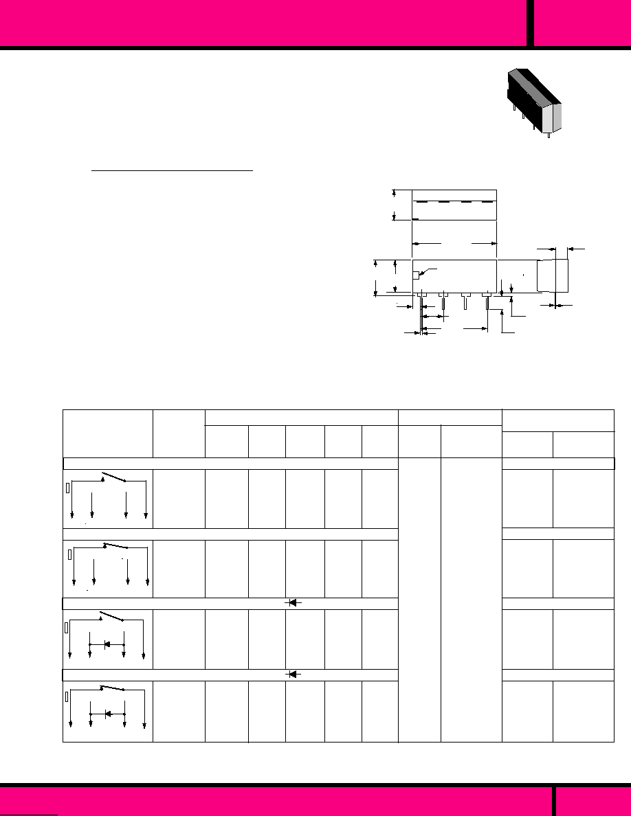
CONSULT FACTORY FOR COMPLETE PART NUMBER
WITH REQUIRED OPTIONS
W117SIP-1
W117SIP-3
W117SIP-5
W117SIP-22
W117SIP-23
W117SIP-24
W117SIP-6
W117SIP-8
W117SIP-10
W117SIP-18
W117SIP-25
W117SIP-26
7
7
1
3
5
1
3
5
+
1
3
5
+
-
1
3
5
+
-
7
7
500
1870
3200
500
1200
2200
500
1870
3200
500
1200
2200
MINIMUM
DROPOUT
MAXIMUM
PULL-IN
COIL Measured @ 25�C
50
77
180
50
120
270
50
77
180
50
120
220
5
12
24
5
12
24
5
12
24
5
12
24
CIRCUIT
DIAGRAM
TOP VIEW
SPST - N.O. WITH
CLAMPING DIODE
SPST - N.C.
SPST - N.O.
SPST - N.C. WITH
CLAMPING DIODE
NOMINAL
INPUT
VOLTAGE
MAXIMUM CONTACT RATING
CROSS REFERENCE
TO
POTTER &
BRUMFIELD
HAMLIN
PART
NUMBERS
NOMINAL
RESIS-
TANCE
(OHMS)
NOMINAL
POWER
(mW)
4.0
9.6
19.2
4.0
9.6
19.2
4.0
9.6
19.2
4.0
9.6
19.2
0.5
1.0
2.0
0.5
1.0
2.0
0.5
1.0
2.0
0.5
1.0
2.0
3621A0500
3621A1200
3621A2400
-
-
-
3621A0510
3621A1210
3621A2410
-
-
-
JWS-117-1
JWS-117-3
JWS-117-5
JWD-171-12
JWD-171-14
JWD-171-15
JWS-117-6
JWS-117-8
JWS-117-10
JWD-171-17
JWD-171-19
JWD-171-30
10VA
0.5 AMP
200VDC
1.5 AMPS
.030 Max.
(.762)
.010 Typ.
(.25)
Pin No. 1
Indicator
.600
(15.2)
.020 Typ.
(.51)
.075 Max.
(1.90)
.750 Max.
(19.5)
.110
(2.79)
.260 Max
(6.60)
.290 Max.
(7.36)
Dimensions shown are in "INCHES" & (Millimeters)
OUTLINE DIMENSIONS
.200Typ.
(5.08)
.140 Max.
(3.55)
.290 Max.
(7.36)
NOTE: MAGNECRAFT FOOT PRINT IS IDENTICAL TO COMPETITOR PART NUMBERS SHOWN. COIL RESISTANCE MAY DIFFER
SLIGHTLY FOR THE NOMINAL VOLTAGES SHOWN.
PART NUMBERS SHOWN ALSO AVAILABLE THRU STOCKING DISTRIBUTION.
Package Material:
Contact Material:
Ambient Temperature:
Dielectric Strength:
Insulation Resistance:
Capacitance:
Shock Resistance:
Vibration Resistance:
Operate Time:
Release Time:
Life
SWITCHING
LOAD
CONTINUOUS
CARRY CURRENT
WEBSITE: www.magnecraft.com - EMAIL:info@magnecraft.com - FAX ON DEMAND 1-800/891-2957 - DOCUMENT 100
SIP
SINGLE IN-LINE PACKAGE REED RELAY
PAGE 63
Epoxy, molded
Rhodium
- 40�C to + 85�C
150 V rms Across open contacts
500 V rms all other points
1000 Megohms Min.
1.0 pF typical coil to contacts
50 G's
20 G's to 200 Hz
1 Millisecond Max.
1 Millisecond Max.
50 Million operations , 5-10V @ 10 mA
100 Million operations no load
CLASS 117 "SIP"
0.5 AMP SWITCHING
SPST-N.O. OR N.C. CONTACTS
SPECIFICATIONS CLASS 117SIP
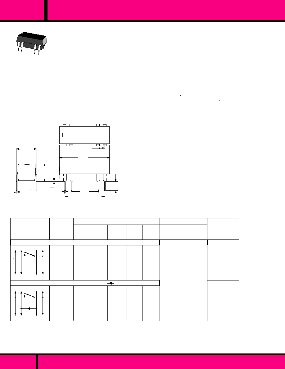
CLASS 107 DUAL IN-LINE PACKAGE REED RELAY
.020
(0.51)
.300
(7.62)
.600
(15.2)
.020 typ.
(0.51)
.400
(10.1)
.750 Max.
(19.05)
.100 typ.
(2.54)
.010
(.254)
1
14
8
14 13
9
2
6
1
7
8
14 13
9
2
6
1
7
+
5
12
24
5
12
24
3.8
9.0
18.0
3.8
9.0
18.0
0.5
1.0
2.0
0.5
1.0
2.0
500
1200
2200
500
1200
2200
50
120
260
50
120
260
NOMINAL
INPUT
VOLTAG
E
SPST - N.O. WITH
CLAMPING DIODE
SPST - N.O.
W107DIP-1
W107DIP-3
W107DIP-4
W107DIP-5
W107DIP-7
W107DIP-8
PART NUMBERS SHOWN ALSO AVAILABLE THRU STOCKING DISTRIBUTION.
MAXIMUM
SWITCHING
LOAD
1 0 V A
0.5 AMP
100 VDC
MAXIMUM
CONTINUOUS
CARRY CURRENT
MAX. CONTACT RATING
1.5 AMPS
CROSS
REFERENCE
TO
POTTER &
BRUMFIELD
NOMINAL
POWER
(mW)
MINIMUM
DROPOUT
MAXIMUM
PULL-IN
RELAY PART
NUMBERS
CIRCUIT
DIAGRAM
TOP VIEW
NOMINAL
RESIS-
TANCE
(OHMS)
JWD-107-1
JWD-107-3
-
JWD-107-5
JWD-107-7
-
DIP
Epoxy, molded
Rhodium
- 40�C to + 85�C
150 V rms Across open contacts
500 V rms all other points
1000 Megohms Min.
2.0 pF typical coil to contacts
1 Milliseconds Max @ Nominal.
1 Milliseconds Max @ Nominal.
50 G's
20 G's to 200 Hz
50 Million operations at 5-10V @ 10mA
100 Million operations no load
Any
1 gram approx.
Package Material:
Contact Material:
Ambient Temperature:
Dielectric Strength:
Insulation Resistance:
Capacitance:
Operate Time:
Release Time:
Shock Resistance:
Vibration Resistance:
Life
Operating Position:
Weight:
.150 Typ.
(3.81)
.275
(6.98)
COIL Measured @ 25�C
All DIP configurations are available with Magnetic Shielding (internal)
and /or Low level applications on special order.
Contact factory for special part numbers.
PAGE 71
WEBSITE: www.magnecraft.com - EMAIL:info@magnecraft.com - FAX ON DEMAND 1-800/891-2957 - DOCUMENT 100
107 DIP RELAY
EPOXY MOLDED
PROVIDES 4 HOOK-UP
PINS TO COIL.
SEE SECTION 10 FOR MATING SOCKET
SPECIFICATIONS CLASS 107DIP

PACKAGE STYLE
FOR W172 DIPS
DPDT
PAGE 72
WEBSITE: www.magnecraft.com - EMAIL:info@magnecraft.com - FAX ON DEMAND 1-800/891-2957 - DOCUMENT 100
SEE SECTION 10 FOR MATING SOCKET
Epoxy, molded
Rhodium or Mercury (as selected)
- 40�C to + 85�C
150 V rms Across open contacts
500 V rms all other points
1000 Megohms Min.
1.0 pF typical coil to contacts
50 G's
20 G's to 200 Hz
1 Millisecond max.
1 Millisecond max.
50 Million operations, 5-10V @ 10mA
100 Million operations Low Level
Package Material:
Contact Material:
Ambient Temperature:
Dielectric Strength:
Insulation Resistance:
Capacitance:
Shock Resistance:
Vibration Resistance:
Operate Time:
Release Time:
Life
OUTLINE DIMENSIONS
Dimensions shown are in "INCHES" & (Millimeters)
.020
(0.51)
.300
(7.62)
.600
(15.2)
.020 typ.
(0.51)
.400
(10.1)
.750 Max.
(19.05)
.100 typ.
(2.54)
.010
(.254)
1
14
.150 Typ.
(3.81)
.275
(6.98)
SPECIFICATIONS 172DIP (DPDT)
Package Material
Contact Material:
Coil Resistance:
Contact Resistance:
Ambient Temperature:
Dielectric Strength::
Coil to contact:
Insulation Resistance:
Operate Time
Release Time:
Life:
Plastic
Rhodium
�
10% @ 20�C
150 M
max.
- 40�C to + 85�C
150 VDC min.
500 VDC min.
1000 Megohms Min.
0.7 Millisecond max. (including bounce)
1 Millisecond max.
50 million operations, 50V/50mA:
80 million operations, 10v/10mA:
WHEN SPACING DIP RELAYS, EXCEPT FOR THE LATCH VERSION, THE RELAYS REQUIRE 3/4 INCH SPACING FROM THE SIDE
OF THE ADJACENT RELAYS. LATCH RELAYS REQUIRE 1 INCH SPACING BETWEEN ADJACENT RELAYS FROM END TO END
AND CENTER LINE TO CENTER LINE.
.125
(3.20)
.082 Typ.
(2.09)
.393
(10.0)
�
.003
.338
(8.60)
.300
(7.62)
�
.003
.046 Typ.
(1.19)
.025
(.635)
�
.003
.600
(15.24)
�
.003
0.10 Typ
(2.54)
.750
(19.0)
�
.003
�
.003
PIN 1 LOCATION
Dimensions shown are in "INCHES" & (Millimeters)
FOOTPRINT AND SCHEMATIC IS PIN FOR PIN
EQUIVALENT TO FORMER DPDT MODELS
SPECIFICATIONS 171DIP & 172 (SPDT)
171 & 172 (SPDT)
DIP
SPECIFICATIONS CLASS 172 & 172 DIPS

PAGE 73
WEBSITE: www.magnecraft.com - EMAIL:info@magnecraft.com - FAX ON DEMAND 1-800/891-2957 - DOCUMENT 100
721A0500
721A1200
721A2400
721A0510
721A1210
721A2410
721B0500
721B1200
721B2400
721B0510
721B1210
721B2410
722A0500
722A1200
722A2400
722A0510
722A1210
722A2410
-
-
JWD-171-5
-
-
JWD-171-10
JWD-171-12
JWD-171-14
JWD-171-15
JWD-171-17
JWD-171-19
JWD-171-20
JWD-171-21
JWD-171-23
JWD-171-24
JWD-171-25
JWD-171-27
JWD-171-28
SPST - N.O.
SPST - N.C. WITH
CLAMPING DIODE
SPST - N.O. WITH
CLAMPING DIODE
8
14 13
9
2
6
1
7
8
14 13
9
2
6
1
7
+
8
14 13
9
2
6
1
7
8
14 13
9
2
6
1
7
+
W171DIP-2
W171DIP-4
W171DIP-5
W171DIP-7
W171DIP-9
W171DIP-10
W171DIP-12
W171DIP-14
W171DIP-15
W171DIP-17
W171DIP-19
W171DIP-20
W171DIP-21
W171DIP-23
W171DIP-24
W171DIP-25
W171DIP-27
W171DIP-28
8
9
6
7
14 13
2
1
+
DPST - N.O.
8
14 13
9
2
6
1
7
DPST - N.O. WITH
CLAMPING DIODE
CIRCUIT
DIAGRAM
TOP VIEW
PART
NUMBERS
COIL Measured @ 25�C
MAXIMUM CONTACT RATING
1.5 AMPS
1.5 AMPS
1.5 AMPS
10VA
0.5 AMP
100VDC
NOMINAL
RESIS-
TANCE
(OHMS)
NOMINAL
INPUT
VOLTAGE
10VA
0.5 AMP
100VDC
10VA
0.5AMP
100VDC
10VA
0.5 AMP
100VDC
10VA
0.5 AMP
100VDC
1.5 AMPS
1.5 AMPS
10VA
0.5 AMP
100VDC
5
12
24
5
12
24
5
12
24
5
12
24
5
12
24
5
12
24
3.8
9.0
18.0
3.8
9.0
18.0
3.8
9.0
18.0
3.8
9.0
18.0
3.8
9.0
18.0
3.8
9.0
18.0
0.5
1.0
2.0
0.5
1.0
2.0
0.5
1.0
2.0
0.5
1.0
2.0
0.5
1.0
2.0
0.5
1.0
2.0
500
1200
2200
500
1200
2200
500
1200
2200
500
1200
22 00
125
500
2000
200
500
2200
50
120
270
50
120
270
50
120
270
50
120
270
125
300
270
125
290
270
CROSS REFERENCE
TO
HE-
HAMLIN
POTTER &
BRUMFIELD
1.5AMPS
SPST - N.C.
NOMINAL
POWE
(mW)
PART NUMBERS SHOWN ALSO AVAILABLE THRU STOCKING DISTRIBUTION
MINIMUM
DROPOUT
MAXIMUM
PULL-IN
SWITCHING
LOAD
CONTINUOUS
CARRY CURRENT
MIL SPECIFICATION MIL-83516/1 AND /4 VERSIONS AVAILABLE CONSULT FACTORY
SEE SPECIFICATIONS AND OUTLINE DIMENSIONS FOR 171DIP
DIP
DUAL IN-LINE PACKAGE REED RELAY

DUAL IN-LINE PACKAGE REED RELAY
PAGE 74
WEBSITE: www.magnecraft.com - EMAIL:info@magnecraft.com - FAX ON DEMAND 1-800/891-2957 - DOCUMENT 100
DIP
NOMINAL
RESIS-
TANCE
(OHMS)
MINIMUM
DROPOUT
MAXIMUM
PULL-IN
NOMINAL
INPUT
VOLTAGE
CROSS REFERENCE
T O
POTTER &
BRUMFIELD
PART
NUMBERS
CIRCUIT
DIAGRAM
TOP VIEW
NOMINAL
POWER
(mW)
CONTINUOUS
CARRY CURRENT
SWITCHING
LOAD
COIL Measured @ 25�C
MAXIMUM CONTACT RATING
SPDT WITH
CLAMPING DIODE
SPDT WITH
CLAMPING DIODE
4VA
.25 AMP
100VDC
0.5AMPS
JWD-172-155
JWD-172-157
JWD-172-158
721C0510
721C1210
721C2410
721E0500
721E1200
721E2400
721E0510
721E1210
721E2410
JWD-172-159
JWD-172-161
JWD-172-162
-
-
-
-
-
-
W172DIP-147
W172DIP-149
W172DIP-150
W172DIP-31
W172DIP-33
W172DIP-34
W172DIP-35
W172DIP-37
W172DIP-38
5
12
24
5
12
24
5
12
24
0.5
1.0
2.0
0.5
1.0
2.0
0.5
1.0
2.0
200
1000
2200
500
1000
2200
500
1000
2200
125
144
180
125
290
270
125
300
270
4VA
.25 AMP
100VDC
0.5AMPS
4VA
.25 AMP
100VDC
0.5AMPS
4VA
.25 AMP
100VDC
0.5 AMPS
3.8
9.0
18.0
3.8
9.0
18.0
3.8
9.0
18.0
SPDT
7
8
7
14 13
1
2
6
14 13
9
1
2
6
1
2
7
6
+
8
14 13
9
9
8
1
2
7
6
8
14 13
9
+
721C0500
721C1200
721C2400
W172DIP-141
W172DIP-145
W172DIP-146
5
12
24
3.8
9.0
18.0
0.5
1.0
2.0
200
1000
2200
125
144
180
HAMLIN
HE-
MAGNECRAFT & STRUTHERS-DUNN - SPST-NO
LATCHING
7
8
6
1
14 13
9
+
OPERATE
RESET
2
+
MRRDL1AS8-5D
MRRDL1AS8-12D
MRRDL1AS8-24D
5
12
24
SPDT
3.8
9.0
18.0
0.5
1.0
2.0
750
1000
4600
35
145
125
10VA
0.5AMP
100VDC
1.5 AMPS
PART NUMBERS SHOWN ALSO AVAILABLE THRU STOCKING DISTRIBUTION

DUAL IN-LINE PACKAGE REED RELAY
PAGE 75
WEBSITE: www.magnecraft.com - EMAIL:info@magnecraft.com - FAX ON DEMAND 1-800/891-2957 - DOCUMENT 100
DIP
PACKAGE STYLE
FOR W172 DIPS
DPDT
171 & 172 (SPDT)
PART NUMBERS SHOWN ALSO AVAILABLE THRU STOCKING DISTRIBUTION
8
14 13
9
2
6
1
7
W172DIP-17
W172DIP-19
W172DIP-20
8
14 13
9
2
6
1
7
+
W172DIP-21
W172DIP-23
W172DIP-24
W172DIP-1
W172DIP-3
W172DIP-4
W172DIP-5
W172DIP-7
W172DIP-8
MAXIMUM CONTACT RATING
NOMINAL
RESIS-
TANCE
(OHMS)
MAXIMUM
PULL-IN
COIL Measured @ 25�C
MINIMUM
DROPOUT
CIRCUIT
DIAGRAM
TOP VIEW
PART
NUMBERS
10VA
0.5 AMP
100VDC
1.0 AMPS
SEE SPECIFICATIONS AND OUTLINE DIMENSIONS FOR 172DIP (DPDT)
DPDT
NOMINAL
INPUT
VOLTAGE
NOMINAL
POWER
(mW)
SWITCHING
LOAD
CONTINUOUS
CARRY CURRENT
DPDT WITH
CLAMPING DIODE
172 DIPS WITH DPDT
CONTACT ARRANGEMENTS
HAVE A NEW PACKAGE
STYLE.
NEW PACKAGE SWITCHES
HIGHER CURRENT UP TO 0.5
AMP @ 100 VDC
5
12
24
3.8
9.0
18.0
0.3
0.3
0.3
46
266
1066
540
540
540
10VA
0.5 AMP
100VDC
1.0 AMPS
5
12
24
3.8
9.0
18.0
0.3
0.3
0.3
46
266
1066
540
540
540
0.5
1.0
2.0
0.5
1.0
2.0
200
500
2200
200
500
2200
125
300
270
125
300
270
5
12
24
5
12
24
3.8
9.0
18.0
3.8
9.0
18.0
CIRCUIT
DIAGRAM
TOP VIEW
8
14 13
9
1
2
7
6
8
14 13
9
1
2
7
6
+
MAXIMUM CONTACT RATING
NOMINAL
RESIS-
TANCE
(OHMS)
MAXIMUM
PULL-IN
NOMINAL
INPUT
VOLTAGE
COIL Measured @ 25�C
0.5 AMPS
4VA
.25 AMP
100VDC
0.5 AMPS
4VA
.25 AMP
100VDC
SPDT
CROSS REFERENCE
TO
JWD-172-1
JWD-172-3
JWD-172-4
JWD-172-5
JWD-172-7
JWD-172-8
721R0500
721R1200
721R2400
721R0510
721R1210
721R2410
PART
NUMBERS
SPDT WITH
CLAMPING DIODE
SWITCHING
LOAD
CONTINUOUS
CARRY CURRENT
MINIMUM
DROPOUT
HAMLIN
HE-
POTTER &
BRUMFIELD
NOMINAL
POWER
(mW)
SEE SPECIFICATIONS AND OUTLINE DIMENSIONS FOR 172DIP (SPDT)
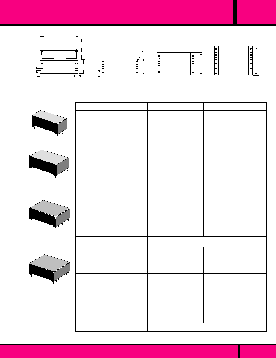
PAGE 76
WEBSITE: www.magnecraft.com - EMAIL:info@magnecraft.com - FAX ON DEMAND 1-800/891-2957 - DOCUMENT 100
MINIATURE
REED
GENERAL SPECIFICATIONS MINIATURE REED RELAYS
DIMENSIONS SHOWN ARE IN INCHES AND ( MILLIMETERS )
SIZE IV
.900
(22.86)
BOTTOM VIEW ALL SIZES
1.15 Max.
(29.2)
.075
(1.9)
.050
(1.27) Typ.
1.00
(25.4)
SIZE I
.125 (3.2) Typ.
.355
(9.0)
.400
(10.16)
SIZE II
.500
(12.7)
.100
(2.54) Typ.
Slotted holes for
Terminal Pins.
SIZE III
.700
(17.8)
SIZE I
SIZE III
SIZE IV
SIZE II
Mercury
(SPDT)
Mercury
DPDT
101/193
104/193
131
134
SPST-NO
SPST-NO
Latching
(SPST-NO)
3PST-NO
Latching
up to 6PST-NO
SPDT, DPDT
for 104 Series
SPDT,DPDT,
3PDT,4PDT
(193 Series)
SPST-NO
or
DPST-NO
Mercury
10 VA
200DC/130 AC
0.5 AMPS
2 AMPS
4VA
100 VDC
0.5 AMPS
1 AMPS
50VA
500 VDC
2 AMPS
3 AMPS
50VA
500 VDC
2 AMPS
3 AMPS
200 VDC
500 VDC
1000 VDC
1000 VDC
1000 VDC
1000 VDC
.3pF
2.0 pF
3.0pF
.9pF
2.0 pF
2.5pF
50 x 10
8
5 x 10
8
at low level
- 37�C
- 40�C to + 105�C
Vertical
�
15�
40 x 10
8
3 x 10
8
at low level
.
3pf Typical
Form "A" 2.0 pF Typ.
Form "C" 3.0pF Typ.
85 �C or ( 120 �C -70� x [ Coil Power]) whichever is lower
- 40�C
- 60�C to + 105�C
ANY
10 Million Operations
100 Million Operations
at Low level
1.0 mS, for N.O.
1.0 mS, for N.C.
2.0 mS, for
N.O.
2300
�
S
2000
�
S
1.0 mS for NO
1.5 mS for NC
2.0 mS
2.5 mS
1.0 mS, for N.O.
1.5 mS, for N.C.
Dust covered, Epoxy Encapsulated is Standard.
10
10
Min.
10
10
Min.
10
9
Min.
200 Milliohms Max.
100 Milliohms Max. Contact
resistance Stability
�
10% over Life.
STANDARD PRINTED CIRCUIT RELAY HAS 1.00" X 0.1" GRID SPACING
CONTACT CONFIGURATION:
CONTACT RATING MAX. (Resistive Load):
SWITCHING VOLTAGE MAX.
SWITCHING CURRENT MAX.
CARRY CURRENT MAX.
INITIAL CONTACT RESISTANCE
( IN MILLIOHMS ):
INSULATION RESISTANCE (Ohms)
TESTED AT 100 VDC:
DIELECTRIC STRENGTH:
MIN. ACROSS OPEN CONTACTS:
MIN. BETWEEN MUTUALLY
INSULATED POINTS:
CAPACITANCE: ( non-shielded relay)
ACROSS OPEN CONTACTS:
OPEN CONTACTS TO COIL:
CLOSED CONTACTS TO COIL:
TEMPERATURE:
MAX. AMBIENT OPERATING (�C )
TEMPERATURE:
MIN. AMBIENT OPERATING ( �C )
STORAGE TEMPERATURE:
MOUNTING POSITION:
LIFE AT RATED LOAD:
With appropriate Contact protection
( End of life 1 Ohm )
OPERATE TIME: (Typical- in Micro-Sec.]).
TYPICAL RELEASE TIME: (in Micro-Sec.)
Diode Suppression:
No Suppression:
PACKAGING:
RELAY CLASS
OUTLINE DIMENSIONS
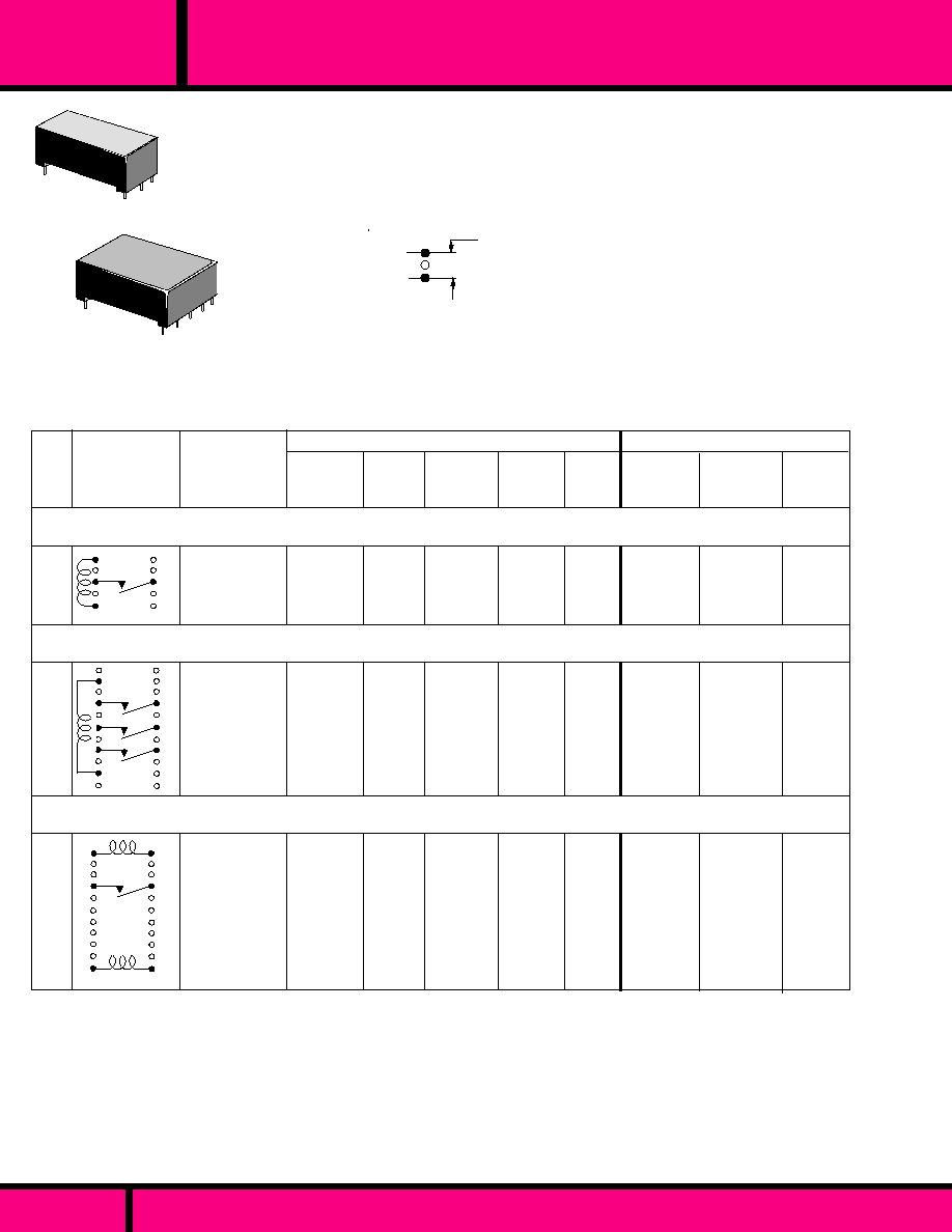
PIN SPACING OF 0.100" IS STANDARD. PIN SPACING OF 0.150 IS
AVAILABLE ON SPECIAL ORDER. ALSO AVAILABLE ARE MODELS
WITH ELECTROSTATIC SHIELDS. CONSULT FACTORY FOR PART
NUMBERS. NON-STANDARD SCHEMATICS AND PIN-OUTS CAN
ALSO BE PRODUCED FOR SPECIFIC CUSTOMER REQUIREMENTS.
Spacing between filled in circles in schematics are on
a .100 Grid Pattern. Pin omitted on unfilled circles.
.100
(2.54) Typ.
PAGE 77
WEBSITE: www.magnecraft.com - EMAIL:info@magnecraft.com - FAX ON DEMAND 1-800/891-2957 - DOCUMENT 100
REED
MINIATURE
CLASS 101 DRY MINIATURE REED RELAY
SIZE I
SIZE III
1
5
6
2
2
1
11
12
Latch
(Set)
De-Latch
(Reset)
+
+
-
-
5/5
12/12
-
-
W101LMPCX-16
W101LMPCX-17
1
2
11
12
W101MPCX-5
W101MPCX-6
W101MPCX-7
5
12
24
4.0
9.0
18.0
0.5
1.0
2.0
90
430
1500
10 VA
CIRCUIT
DIAGRAM
TOP VIEW
60
60
280
340
380
COIL MEASURED AT 25�C
MAX. CONTACT RATING
SWITCHING
CURRENT &
VOLTAGE
CARRY
CURRENT
2 AMPS
2 AMPS
I
SPST-NO
3PST-NO
SPST-NO
MAGNETIC LATCH
CASE
SIZE
10 VA
0.5 AMP
200 VDC
0.5 AMP
200 VDC
NOMINAL
INPUT
VOLTAGE
MAXIMUM
PULL-IN
MINIMUM
DROPOUT
NOMINAL
RESIS-
TANCE
(OHMS)
NOMINAL
POWER
(mW)
425/425
2500/2500
3.8
9.0
To Set
or Reset
MAX.
SWITCHING
LOAD
12
24
9.0
18.0
1.0
2.0
1400
3300
10 VA
0.5 AMP
200 VDC
102
175
W101MPCX-2
W101MPCX-3
2 AMPS
PART
NUMBERS
PART NUMBERS SHOWN AVAILABLE THRU STOCKING DISTRIBUTION
III
III

CLASS 131 MERCURY
PAGE 78
WEBSITE: www.magnecraft.com - EMAIL:info@magnecraft.com - FAX ON DEMAND 1-800/891-2957 - DOCUMENT 100
REED
MINIATURE
SPST-NO MERCURY
1
2
UP
W131MPCX-7
W131MPCX-8
12
24
9.0
18.0
1.0
2.0
626
480
230
1200
3 AMPS
DPST-NO MERCURY
50 VA
2.0 AMP
500 VDC
1
5
6
2
UP
W131MPCX-3
W131MPCX-4
3 AMPS
50 VA
2.0 AMP
500 VDC
330
1400
435
410
12
24
9.0
18.0
1.0
2.0
PART NUMBERS SHOWN AVAILABLE THRU STOCKING DISTRIBUTION
10
9
II
1
SIZE I
SIZE II
PIN SPACING OF 0.100" IS STANDARD. PIN SPACING OF 0.150 IS
AVAILABLE ON SPECIAL ORDER. ALSO AVAILABLE ARE MODELS
WITH ELECTROSTATIC SHIELDS. CONSULT FACTORY FOR PART
NUMBERS. NON-STANDARD SCHEMATICS AND PIN-OUTS CAN
ALSO BE PRODUCED FOR SPECIFIC CUSTOMER REQUIREMENTS.
Spacing between filled in circles in schematics are on
a .100 Grid Pattern. Pin omitted on unfilled circles.
.100
(2.54) Typ.
For Class 131 allow a minimum of 30 seconds after mounting for excess Mercury to clear from the contacts before using.

COIL MEASURED AT 25�C
MAX. CONTACT RATING
1
5
6
2
1
2
W104MPCX-3
24
W104MPCX-6
12
626
230
9.0
18.0
2.0
2600
220
4 VA
DPDT
SPDT
CASE
SIZE
SWITCHING
CURRENT &
VOLTAGE
CARRY
CURRENT
0.5 AMPS
0.5 AMPS
I
0.25 AMP
100VDC
4 VA
1.0
0.25 AMP
100VDC
CIRCUIT
DIAGRAM
TOP VIEW
NOMINAL
INPUT
VOLTAGE
MAXIMUM
PULL-IN
MINIMUM
DROPOUT
NOMINAL
RESIS-
TANCE
(OHMS)
NOMINAL
POWER
(mW)
DPDT
PART
NUMBERS
MAX.
SWITCHING
LOAD
1
7
8
2
0.5
1.0
2.0
556
626
480
45
230
1200
5
12
24
4.0
9.0
18.0
W104MPCX-149
W104MPCX-150
W104MPCX-151
II
0.5 AMPS
0.25 AMP
100VDC
4 VA
PART NUMBERS SHOWN AVAILABLE THRU STOCKING DISTRIBUTION
9
10
II
PAGE 79
MINIATURE
CLASS 104 DRY MINIATURE REED RELAY
SIZE I
SIZE III
Spacing between filled in circles in schematics are on
a .100 Grid Pattern. Pin omitted on unfilled circles.
.100
(2.54) Typ.
PIN SPACING OF .100" IS STANDARD. PIN SPACING OF .150 IS
AVAILABLE ON SPECIAL ORDER. ALSO AVAILABLE ARE MODELS
WITH ELECTROSTATIC SHIELDS. CONSULT FACTORY FOR PART
NUMBERS. NONSTANDARD SCHEMATICS AND PIN-OUTS CAN
ALSO BE PRODUCED FOR SPECIFIC CUSTOMER REQUIREMENTS.
WEBSITE: www.magnecraft.com - EMAIL:info@magnecraft.com - FAX ON DEMAND 1-800/891-2957 - DOCUMENT 100
REED

CLASS 134 MERCURY
For Class 134 allow a minimum of 30 seconds after mounting for excess Mercury to clear from the contacts before using.
1
7
8
2
UP
50 VA
1.0 AMP
500 VDC
UP
1
7
8
2
+
-
5
12
24
0.5
1.0
2.0
W134MPCX-1
W134MPCX-2
W134MPCX-3
417
435
410
60
330
1400
SPDT MERCURY
DPDT MERCURY WITH
CLAMPING DIODE
DPDT MERCURY
2.0 AMPS
II
II
I
50 VA
50 VA
W134MPCX-10
W134MPCX-11
5
12
4.0
9.6
1.0
1.0
45
230
560
620
1.0 AMP
500 VDC
2.0 AMPS
W134MPCX-7
W134MPCX-8
5
12
4.0
9.6
0.5
1.0
45
230
560
620
2.0 AMPS
4.0
9.0
18.0
1.0 AMP
500 VDC
1
5
UP
6
2
PART NUMBERS SHOWN AVAILABLE THRU STOCKING DISTRIBUTION
PAGE 80
WEBSITE: www.magnecraft.com - EMAIL:info@magnecraft.com - FAX ON DEMAND 1-800/891-2957 - DOCUMENT 100
REED
MINIATURE
SIZE I
SIZE II
PIN SPACING OF .100" IS STANDARD. PIN SPACING OF .150 IS
AVAILABLE ON SPECIAL ORDER. ALSO AVAILABLE ARE MODELS
WITH ELECTROSTATIC SHIELDS. CONSULT FACTORY FOR PART
NUMBERS. NONSTANDARD SCHEMATICS AND PIN-OUTS CAN
ALSO BE PRODUCED FOR SPECIFIC CUSTOMER REQUIREMENTS.
Spacing between filled in circles in schematics are on
a .100 Grid Pattern. Pin omitted on unfilled circles.
.100
(2.54) Typ.

PIN SPACING OF 0.100" IS STANDARD. PIN SPACING OF 0.150 IS
AVAILABLE ON SPECIAL ORDER. ALSO AVAILABLE ARE MODELS
WITH ELECTROSTATIC SHIELDS. CONSULT FACTORY FOR PART
NUMBERS. NONSTANDARD SCHEMATICS AND PIN-OUTS CAN
ALSO BE PRODUCED FOR SPECIFIC CUSTOMER REQUIREMENTS.
Spacing between filled in circles in schematics are on
.100 Grid Patterns. Pin omitted on unfilled circles.
.100
(2.54) Typ.
PAGE 81
WEBSITE: www.magnecraft.com - EMAIL:info@magnecraft.com - FAX ON DEMAND 1-800/891-2957 - DOCUMENT 100
REED
MINIATURE
CLASS 193 DRY MINIATURE REED RELAY
SIZE I
SIZE II
6
1
2
3
4
5
I
1
3
5
6
2
4
I
1
3
5
6
2
4
II
7
8
1
3
5
II
7
8
6
2
4
CASE
SIZE
NOMINAL
INPUT
VOLTAGE
CARRY
CURRENT
COIL MEASURED AT 25�C
MAX. CONTACT RATING
10 VA
2 AMPS
NOMINAL
POWER
(mW)
W193RE2C3-6G
W193RE2C3-12G
W193RE2C3-24G
5
12
24
4.0
9.0
18.0
0.5
1.0
2.0
70
280
1500
360
500
390
4 VA
1 AMP
0.5 AMP
100 VDC
10 VA
2 AMP
0.5 AMP
200 VDC
4.0
9.0
18.0
0.5
1.0
2.0
360
500
390
W193RE2A3-6G
W193RE2A3-12G
W193RE2A3-24G
5
12
24
70
280
1500
4 VA
1 AMP
0.5 AMP
100 VDC
W193RE1C3-5S
W193RE1C3-12G
W193RE1C3-24G
5
12
24
4.0
9.0
18.0
0.5
1.0
2.0
350
420
2300
70
350
250
W193RE1A3-5S
W193RE1A3-12G
W193RE1A3-24G
5
12
24
4.0
9.0
18.0
0.5
1.0
2.0
500
420
2300
50
350
250
0.5 AMP
200 VDC
SWITCHING
CURRENT &
VOLTAGE
PART
NUMBERS
DPDT
DPST-N.O.
SPDT
SPST-N.O.
MINIMUM
DROPOUT
MAXIMUM
PULL-IN
NOMINAL
RESIS-
TANCE
(OHMS)
MAX.
SWITCHING
LOAD
PART NUMBERS SHOWN AVAILABLE THRU STOCKING DISTRIBUTION
CIRCUIT
DIAGRAM
(Top View)

PIN SPACING OF 0.100" IS STANDARD. PIN SPACING OF 0.150 IS
AVAILABLE ON SPECIAL ORDER. ALSO AVAILABLE ARE MODELS
WITH ELECTROSTATIC SHIELDS. CONSULT FACTORY FOR PART
NUMBERS. NONSTANDARD SCHEMATICS AND PIN-OUTS CAN
ALSO BE PRODUCED FOR SPECIFIC CUSTOMER REQUIREMENTS.
Spacing between filled in circles in schematics are on
.100 Grid Patterns. Pin omitted on unfilled circles.
.100
(2.54) Typ.
SIZE III
SIZE IV
PAGE 82
WEBSITE: www.magnecraft.com - EMAIL:info@magnecraft.com - FAX ON DEMAND 1-800/891-2957 - DOCUMENT 100
1
3
5
7
8
6
2
4
9
10
3
5
6
4
7
8
9
10
11
12
2
1
13
15
14
16
6
2
4
8
1
3
5
10
9
7
11
12
2
4
6
8
1
3
5
7
9
10
11
12
W193RE4A3-6G
W193RE4A3-12G
W193RE4A3-24G
W193RE4C3-6G
W193RE4C3-12G
W193RE4C3-24G
W193RE3C3-6G
W193RE3C3-12G
W193RE3C3-24G
W193RE3A3-6G
W193RE3A3-12G
W193RE3A3-24G
PART
NUMBERS
III
III
III
IV
10 VA
2 AMP
0.5 AMP
200 VDC
4 VA
1 AMP
0.5 AMP
100 VDC
10 VA
2 AMP
0.5 AMP
200 VDC
4 VA
1 AMP
0.5 AMP
100 VDC
4.0
9.0
18.0
0.5
1.0
2.0
500
690
500
5
12
24
50
210
1150
4.0
9.0
18.0
0.5
1.0
2.0
5
12
24
720
1030
750
35
140
770
5
12
24
4.0
9.0
18.0
0.5
1.0
2.0
50
210
1150
500
690
500
4.0
9.0
18.0
0.5
1.0
2.0
500
690
500
5
12
24
50
210
1150
NOMINAL
INPUT
VOLTAGE
CARRY
CURRENT
COIL MEASURED AT 25�C
NOMINAL
POWER
(mW)
SWITCHING
CURRENT &
VOLTAGE
MINIMUM
DROPOUT
MAXIMUM
PULL-IN
NOMINAL
RESIS-
TANCE
(OHMS)
MAX.
SWITCHING
LOAD
3PST-N.O.
MAX. CONTACT RATING
4PST-N.O.
4PDT
3PDT
PART NUMBERS SHOWN AVAILABLE THRU STOCKING DISTRIBUTION
CIRCUIT
DIAGRAM
(Top View)
CASE
SIZE
REED
MINIATURE
CLASS 193 DRY MINIATURE REED RELAY

PAGE 83
WEBSITE: www.magnecraft.com - EMAIL:info@magnecraft.com - FAX ON DEMAND 1-800/891-2957 - DOCUMENT 100
P.C. TERMINAL, MOLDED MINIATURE REED RELAY
MR-Y
SERIES
.950
(24.1)
.312
(7.9)
.130
(3.3)
.020 Typ.
(.508)
DIM. "A" SEE CHART
.045 Typ.
(1.14)
.400
(10.1)
.550
(13.9)
.062 R x .032 Deep
.010
(.254)
1.00
(25.4)
Position Reference
DIM. "B" SEE CHART
DIM "A" 0.100 0.10 Grid
DIM."A" 0.150 0.15 Grid
DIM "B" 0.200 0.10 Grid
DIM."B" 0.300 0.15 Grid
DIMENSION CHART
+
SPDT
MR30Y1C
MR35Y1C
*
+
+
SPST-NO
MR30Y1A
MR35Y1A
SPST-NC
MR30Y1B
MR35Y1B
+
DPST-NO
MR30Y2A
MR35Y2A
*
WIRING DIAGRAM
Top View
+
DPDT
MR30Y2C
MR35Y2C
*
*
The MR-Y Series epoxy molded miniature reed relay has terminal pins on each end and
spaced 1 inch apart. It is available with two grid spacings - 0.1 inch or 0.15 inch. Available
contacts range from SPST-NO to DPDT configurations. As an option, Mercury reeds are
available in limited contact configurations. Lower power coils are also available in addition to
optional diode across the coil and electrostatic shielding.
Dimensions shown are in Inches and (Millimeter)
OUTLINE DIMENSIONS
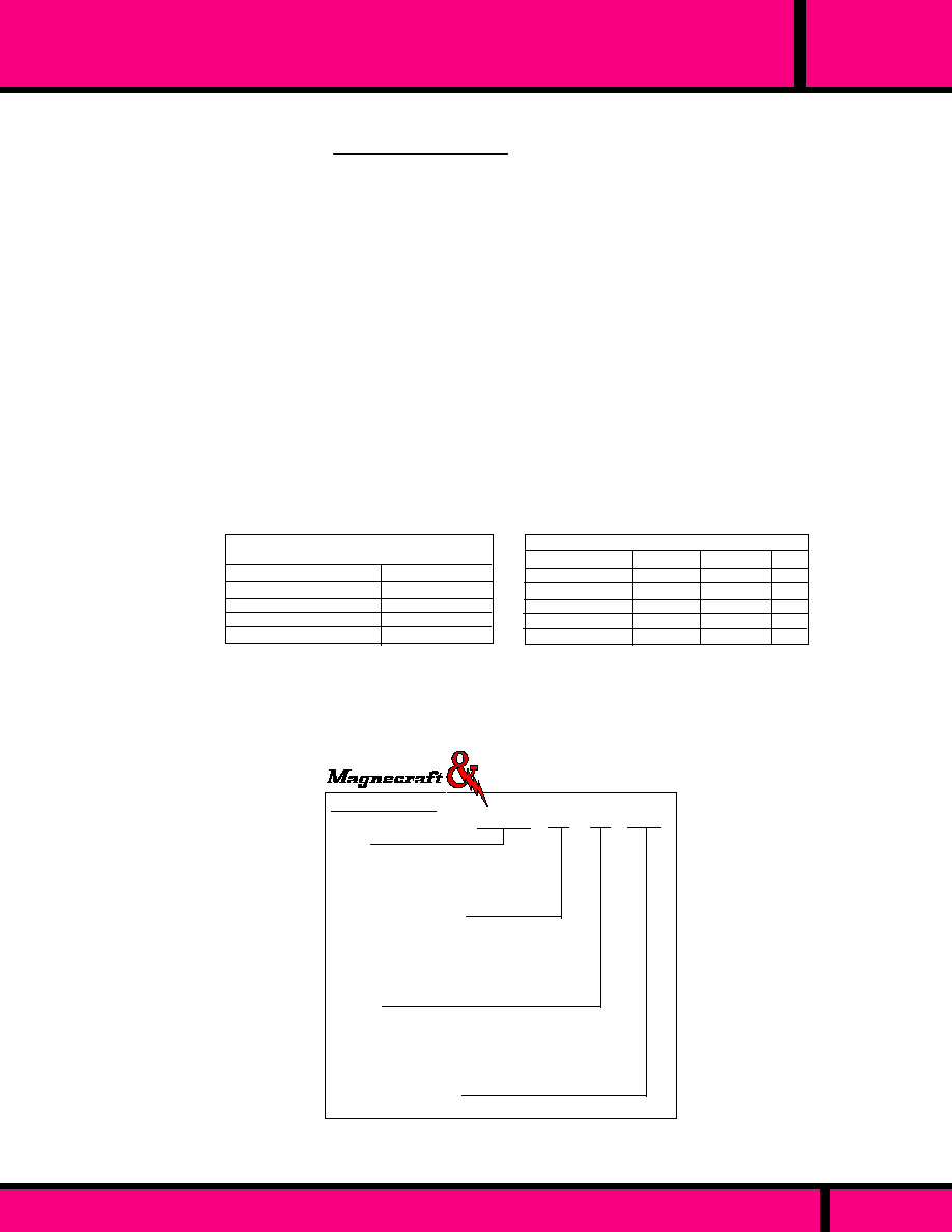
PAGE 84
WEBSITE: www.magnecraft.com - EMAIL:info@magnecraft.com - FAX ON DEMAND 1-800/891-2957 - DOCUMENT 100
MR-Y
SERIES
P.C. TERMINAL, MOLDED MINIATURE REED RELAY
SPECIFICATIONS MR-Y
(Not all Data applies to HG Relays)
Package Material:
Contact Material:
Dielectric Strength:
Insulation Resistance:
Capacitance:
Shock Resistance:
Vibration Resistance:
Operate & Release Time:
Life:
Epoxy, molded
Rhodium
200 V rms Across Open Contacts
1500 V rms All other points
1000 Megohms Min.
0.4 pF typical coil to contacts
50 G's
20 G's to 2000 Hz
2 Milliseconds Max.
10 Million operations at rated load SPST,DPST-NO & NC
100 Million operations no load SPST,DPST-NO & NC
5 Million operations at rated load SPDT, DPDT contacts.
50 Million operations no load, SPDT, DPDT contacts.
ORDERING CODE
Typical Type No.
Series
MR30Y- 0.1 grid, end terminal
Min. P.C. Reed Relay
MR35Y- 0.15 grid, end terminal
Min. P.C. Reed Relay
Contact Arrangements
1A - SPST-NO
2A - DPST-NO
1B - SPST-NC
1C - SPDT
2C - DPDT
Options
Electrostatic Shield (see wiring diagrams)- CODE E
Low Power Coils (Dry Reeds Only) - CODE R
Diode across Coil (Observe Polarity) - CODE V
Mercury Reed Contact, position sensitive
SPST-NO or SPDT - CODE Z
Coil Voltage (DC only)
DC: 5, 12, 24 (Add "D")
MR30Y 2A RV -12D
+
Polarity must be observed for models with Form "B" contacts or optional Diode.
*
Terminal for optional Electrostatic Shield.
HG Contact relays are position sensitive.
VDC
5
12
24
OHMS
150
575
2150
mW
167
250
268
OHMS
80
320
1500
mW
313
450
384
SPDT, DPDT
SPST, DPST
Max. VDC
200
200
28
500
200
Max. mA
500
500
250
2000
1000
VA
10
10
3
50
28
Contacts
SPST-NO
SPST-NC
SPDT, DPDT
SPST-NO (HG)
SPDT, DPDT(HG)
COIL DATA
Power Consumption (mW) - Coil Resistance,
Nominal Voltage
�
10% @ 25�C
CONTACT DATA
Material - Rhodium on Dry Reeds
Must operate at 80% of nominal voltage @ 25�C
Low Power Coils available:
Single Pole - 25mW
Double Pole - 65mW
Struthers-Dunn
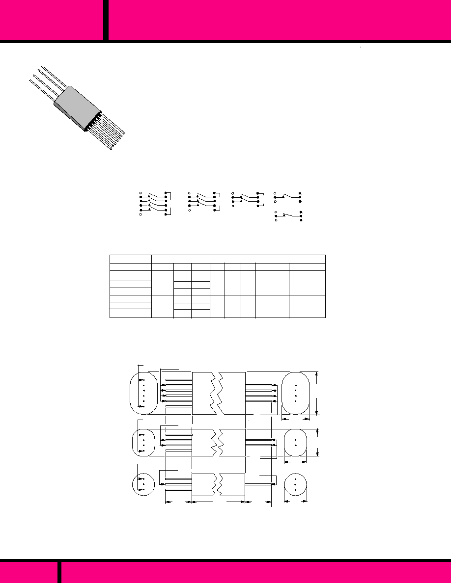
PAGE 85
WEBSITE: www.magnecraft.com - EMAIL:info@magnecraft.com - FAX ON DEMAND 1-800/891-2957 - DOCUMENT 100
SERIES
MRR & RR
AXIAL LEAD, SHIELDED REED RELAY
The MRR and RR Series Axial lead epoxy molded reed relays have solid wire
leads on each end. They are available with two grid spacings - 0.1 inch for the
MRR series and 0.2 inch for the RR series. Available contacts - UP TO 12PST-
NO for the MRR series, and 1 -4PST-NO or NC for the RR series. The MRR and
RR series come with an external Half shield fixed to the body of the relay.
H
A
E
D
F
G
B
F
F
H
B
B
C
G
Max.
Max.
Min.
Min.
Max.
C
Max.
Max.
H
G
Typical Lead spacing .115"
MRR2A,
RR2A
MRR1A,
RR1A, RR1B
MRR4A,
RR4AF
Typical Lead spacing .115"
A B C D E F G H
1.062
�
.005
1.875
.425
.440
.535
.655
.670
.810
.425
.515
.810
.655
.840
1.385
.500
.875
.500
.500
DIMENSIONS
MRR1A
MRR2A
MRR4A
RR1A, RR1B
RR2A
RR4AF
.018 X .030
.055
SERIES
(Inches)
.028
.035
.028
.035 X .061
DIMENSIONAL CHART FOR MRR & RR SERIES RELAYS
To convert Inch dimensions to Millimeter use 25.4 x Dimension = Millimeters.
MRR4A,
RR4AF
MRR2A,
RR2A
MRR3A,
RR3A
MRR1A,
RR1A
RR1B
WIRING DIAGRAM (Terminal view )
OUTLINE DIMENSIONS
See dimensional chart above
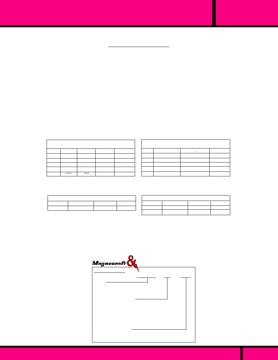
PAGE 86
WEBSITE: www.magnecraft.com - EMAIL:info@magnecraft.com - FAX ON DEMAND 1-800/891-2957 - DOCUMENT 100
SERIES
MRR & RR
AXIAL LEAD, SHIELDED REED RELAY
MRR or RR 2A -12D
Series
MRR- 0.1" Lead spacing
RR- 0.2" Lead spacing
Contact Arrangements
1A - SPST-NO
2A - DPST-NO
3A - 3PST-NO
4A - 4PST-NO
1B - SPST-NC (RR series Only)
Coil Voltage (DC only)
DC: 6, 12, 24, 48 (Add "D")
(5 volt and other voltages available)
ORDERING CODE
Typical Type No.
Struthers-Dunn
Contact Material:
Ambient Temperature:
Dielectric Strength:
Insulation Resistance:
Capacitance:
Shock Resistance:
Vibration Resistance:
Operate & Release Time:
Life:
VDC
6
12
24
48
Must operate at 70% of nominal voltage @ 25�C
OHMS
288
1152
4600
DPST-NO 4PST-NO 12PST-NO
OHMS
144
576
2300
OHMS
24
94
384
1536
OHMS
72
288
1152
3300
SPST-NO
COIL DATA MRR SERIES
Coil Resistance & Nominal Voltage Measured
at
�
10% @ 25�C.
Must operate at 80% of nominal voltage @ 25�C
Options RR only - Preformed leads welded lead extensions.
SPST-NO or NC
VDC
6
12
24
48
OHMS
90
360
1440
5760
OHMS
36
145
580
2300
DPST-NO
OHMS
24
94
384
1536
4PST-NO
COIL DATA RR SERIES
Coil Resistance & Nominal Voltage Measured
at
�
10% @ 25�C.
Contacts
1-4PST-NO
Max. VDC
200
Max. mA
500
VA
10
CONTACT DATA MRR SERIES
Material - Rhodium on Dry Reeds
Contacts
1-4PST-NO
SPST-NC
CONTACT DATA RR SERIES
Material - Rhodium on Dry Reeds
Max. VDC
250
250
VA
15
15
Max. AMPS
1.0
1.0
NOTE: Voltage, Current, and Power ratings in the tables above are independent maximums and no single value
is to be exceeded. Ratings are based on noninductive, straight resistive, AC or DC loads without inrush. Other
loads require contact protection and /or de-rating.
SPECIFICATIONS MRR & RR
Rhodium
- 40�C to + 85�C
MRR 400 V rms Across open contacts
RR 500 V rms Across open contacts
1500 V rms All other points
1000 Megohms Min.
0.4 pF typical coil to contacts
50 G's
MRR - 20 G's to 2000 Hz
RR - 10 G's to 450 Hz
2 to 10 Milliseconds based on the
amount of contacts.
10 Million operations at rated load
200 Million operations no load

RRN
series
OPEN STYLE, METAL COVER/SHIELD REED RELAY
PAGE 87
1.90 Max.
(48.2)
.64 Max.
(16.2)
0.156
(3.9)
.200
(5.0)
.800
(20.3)
2 POLE CASE SIZE
2.50 Max.
(63.5)
.38
(9.6)
.500
(12.7)
+
.958 Wide
.958 Wide
1.418 Wide
RRN2C
RRN1B
RRN2A
0.10
(2.54)
*
.740 Wide
.740 Wide
1.418 Wide
RRN4A
RRN1A
RRN1C
+
1.188 Wide
1.188 Wide
1.418 Wide
RRN3C
RRN2B
RRN3A
*
WIRING DIAGRAMS
(Top View)
OUTLINE DIMENSIONS
Shown in Inchs and (Millimeters)
* See Wiring Diagrams for Width.
The RRN Series is a open construction, one piece nylon bobbin,
P.C. terminal assembly with a metal Cover/Shield (3 sided).
Terminals on 0.2 Inch grid. The 1 and 3
pole units have the middle terminals on
the center line.
WEBSITE: www.magnecraft.com - EMAIL:info@magnecraft.com - FAX ON DEMAND 1-800/891-2957 - DOCUMENT 100

PAGE 88
WEBSITE: www.magnecraft.com - EMAIL:info@magnecraft.com - FAX ON DEMAND 1-800/891-2957 - DOCUMENT 100
RRN
series
OPEN STYLE, METAL COVER/SHIELD REED RELAY
Series
RRN- Semi open, 3 sided shield
Contact Arrangements
1A - SPST-NO
2A - DPST-NO
3A - 3PST-NO
4A - 4PST-NO
1B - SPST-NC
2B -DPST-NC
1C - SPDT
2C - DPDT
Options
Electrostatic Shield (Consult Factory For Wiring
Code E
Diode Across Coil (Observe Polarity, Consult Factory) Code
V
Coil Voltage (DC only)
DC: 6, 12, 24, 48 (Add "D")
(5 volt and other voltages available)
ORDERING CODE
Typical Type No.
RRN 3A EV -12D
SPECIAL OPTIONS
Special Wiring .
Magnetic Latch Version . Consult Factory
Struthers-Dunn
4 POLE
Rhodium
- 40�C to + 85�C
500 V rms Across open contacts
1500 V rms All other points
1000 Megohms Min.
0.4 pF typical coil to contacts
50 G's
RR - 10 G's to 450 Hz
6 Milliseconds max. depending on 6 Milliseconds worst case.
10 Million operations at rated load
200 Million operations no load
all 1-4PST-NO & SPST-NC
50 Million Operations at no load
for all SPDT, DPDT Contacts.
Contact Material:
Ambient Temperature:
Dielectric Strength:
Insulation Resistance:
Capacitance:
Shock Resistance:
Vibration Resistance:
Operate Time:
Release Time:
Life:
SPECIFICATIONS RRN
Max. VDC
250
250
250
Max. Amps
1.0
1.0
0.5
VA
15
15
10
Contacts
1-4PST-NO
1-2PST-NC
SPDT, DPDT
VDC
6
12
24
48
Must operate at 80% of nominal voltage @ 25�C
OHMS
50
200
800
3000
OHMS
150
600
2400
4000
OHMS
100
400
1600
4000
2 POLE
1 POLE
3 POLE
OHMS
40
150
600
2300
NOM.
NOTE: Voltage, Current, and Power ratings in the table
above are independent maximums and no single value is
to be exceeded. Ratings are based on noninductive,
straight resistive, AC or DC loads without inrush. Other
loads require contact protection or de-rating.
COIL DATA
Coil Resistance & Nominal Voltage Measured at
�
10% @ 25�C
CONTACT DATA
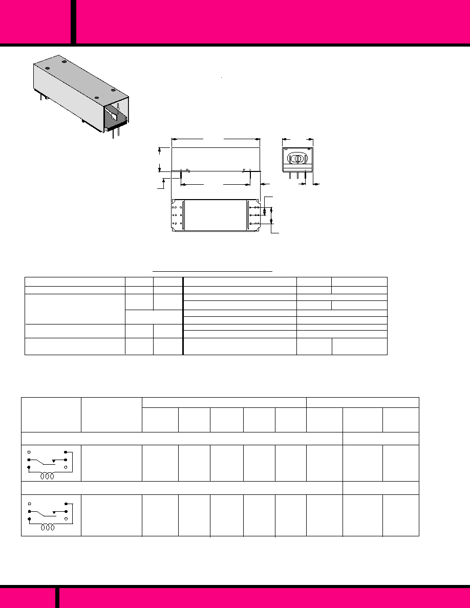
2.67 Max.
(16.5)
.760 Max.
(19.3)
.65 Max.
(16.5)
0.16
(4.0)
.38
(9.6)
.400
(10.1)
.200
(5.0)
.18 Max.
(4.5)
OUTLINE DIMENSIONS
Dimensions shown are in Inch and (Millimeter)
NOMINAL
INPUT
VOLTAGE
COIL MEASURED AT 25�C
MAX. CONTACT RATING
1.0
2.0
SWITCHING
CURRENT &
VOLTAGE
250
1000
CIRCUIT
DIAGRAM
(TOP VIEW)
W102RMPCX-2
W102RMPCX-3
9.0
18.0
250
1000
W102MPCX-7
W102MPCX-8
12
24
9.0
18.0
1.0
2.0
12
24
580 mW
15VA
MAXIMUM
PULL-IN
MINIMUM
DROPOUT
NOMINAL
RESIS-
TANCE
(OHMS)
NOMINAL
POWER
(mW)
CARRY
CURRENT
PART
NUMBERS
PART NUMBERS SHOWN AVAILABLE THRU STOCKING DISTRIBUTION
SPST-N.O. 3 AMP
SPST-N.O. 1 AMP
SWITCHING
LOAD
1 AMP
250VDC
2 AMPS
3 AMP
250VDC
3.5 AMPS
100VA
580 mW
102 102R
200 200
700 VDC 450 VDC
1000 VDC
RELAY CLASS
Capacitance, Non Shield, N.O.:
Insulation Resistance:
Coil Dissipation (mW)
Mounting Position:
Shock (Non operation):
Vibration:
Temperature Range (operating):
Life At rated load:
102 102R
1.0 pf 1.5 pf
10
9
at 100 VDC
50 to 1.5W 600
Any
30 G's 11mS
�
1 mS 1/2 Sign
10 G"s 10 to 1000 Hz
-40�C to + 85�C
200 Million 20 Million
@1A, 115V rms
1.0 2.0
2 2
RELAY CLASS
Contact Resistance Initial:
Dielectric Withstanding voltage:
Across Open Contacts:
Between all other mutually
Insulated points.:
Operate Time (mS):
Bounce Time No Diode (mS):
1 POLE CASE SIZE
1.90 Max.
(48.2)
102
CLASS
OPEN STYLE, METAL COVER/SHIELD REED RELAY
102MPCX/RMPCX
SPST-N.O.
METAL SHIELD ON THREE SIDES.
0.2 GRID SPACING.
GENERAL SPECIFICATIONS 102
PAGE 89
WEBSITE: www.magnecraft.com - EMAIL:info@magnecraft.com - FAX ON DEMAND 1-800/891-2957 - DOCUMENT 100

NOMINAL
RESISTANCE
(OHMS)
NOMINAL
INPUT
VOLTAGE
COIL Measured @ 25�C
CONTACT
CONFIGURATION
DC OPERATED
W120X-14
12 VDC
SPDT
100
CONTACTS
R.F. Load rating:
Contact Configuration:
Contact Resistance (Initial):
VSWR ( Voltage Standing Wave Ratio)
Cross Talk:
TIMING
Operate Time:
Release Time:
DIELECTRIC STRENGTH
All Mutually Insulated current
carrying parts to ground:
Insulation Resistance:
TEMPERATURE
Rated Operation:
LIFE EXPECTANCY
Mechanical:
Electrical:
MISCELLANEOUS
Mounting:
Connectors:
Cable Type:
Cable Impedance:
Weight:
150 Watts max. up to 470 MHz
SPDT (1 Form "C")
50 Milliohms max.
1.25 to 1 max., up to 460 MHz
40 DB min., up to 470 MHz.
15 mS Max. @ Nominal Voltage.
7 mS Max. @ Nominal Voltage.
1000 V rms @ Sea level
1000 Megohms min. 500 V
-55�C to +65�C
100,000 Operations @ Rated Load.
5 Million Operations no load
Panel mount with 2 mount holes.
None
RG58C/U, 12" long, with stripped wire
length of .250"
50 Ohms
3 ozs. 85.0 grams approx.
RG58C/U
RG58C/U
1.73
(44.0)
1.28
(32.5)
.078
(1.98)
1.106
(29.05)
.422
(10.71)
.850
(21.59)
.093
(2.38)
12.0
(304.8)
12.0
(304.8)
.120 Dia thru holes
(2 mounting holes)
.671
(17.0)
.770
(19.5)
.250 Typ.
(6.35)
.312
(7.93)
120 COAXIAL RELAY
PANEL MOUNT WITH RG58C/U
CABLE (50 OHM )
SWITCHING UP TO 470 MHz
PAGE 90
WEBSITE: www.magnecraft.com - EMAIL:info@magnecraft.com - FAX ON DEMAND 1-800/891-2957 - DOCUMENT 100
150 WATT, COAXIAL R.F. SWITCHING RELAY
120
CLASS
GENERAL SPECIFICATIONS CLASS 120
PART NUMBERS SHOWN AVAILABLE THRU STOCKING DISTRIBUTION
PART NUMBER
4
5
1
3
2
WIRING DIAGRAM
Side View Coil Down

SOLID STATE RELAYS
(SSR)
1.5 TO 75 AMPERES
4
S E C T I O N
4
Page 91

RELAY SERIES
FEATURES
OUTPUT DATA
INPUT DATA
GENERAL DATA
DIMENSIONS
APPROVALS
AC - VOLTAGE:
DC - VOLTAGE:
MAXIMUM PULL-IN VOLTAGE:
MINIMUM DROP-OUT VOLTAGE:
INPUT IMPEDANCE:
NOT AVAILABLE
5 & 12 DC
4.3 & 10.3 VDC)
1.5 VDC
15 MILLIAMPS MAX
NOT AVAILABLE
5 & 12 VDCVDC
4.0 & 9.3 VDC
2.0 VDC
15 MILLIAMPS MAX.
H W L
H W L
H W L
.78 X 1.75 X 2.25
0.25 X 0.5 X .875
SCR
25 MILLIAMPS
INSULATION
CHARACTERISTICS
2500 V rms
2500 V rms
.780 X .670 X .990
OUTPUT CONFIGURATION:
MAXIMUN ALLOWABLE
OUTPUT VOLTAGE & LOAD:
OUTPUT DEVICE:
MINIMUM LOAD:
NOT AVAILABLE
5 & 12 VDCVDC
4.0 & 9.3 VDC
2.0 VDC
16 MILLIAMPS MAX.
SCR
25MILLIAMPS
2500 V rms
TRIAC
50 MILLIAMPS
4000 V rms
NOT AVAILABLE
3 TO 32 VDC
3 VDC
1 VDC
1500
DIELECTRIC STRENGTH
.700 X .860 X .860
DC CONTROLLED
INPUT, AC TRIAC
OUTPUT
UP TO 10 AMP LOADS
PHOTO ISOLATED,
ZERO VOLTAGE
SWITCHING.
4000 V rms ISOLATION
INPUT TO OUTPUT.
INTERNAL RC
(SNUBBER) NETWORK
P.C. MOUNT STYLE.
5 OR 12 VDC INPUT
AC OUTPUT
TYPE 230E HAS 1.5
AMP LOAD RATING
TYPE 230T HAS 3.0
AMP LOAD RATING
ZERO VOLTAGE
SWITCHING.
TYPE 230T HAS
BUILT IN HEAT SINK.
5 OR 12 VDC INPUT
AC, TRIAC OUTPUT
UP TO 7 AMP LOADS
PHOTO ISOLATED,
RANDOM TURN-ON
COMPATABLE WITH
TTL GATES.
MOUNTS ON TO-3
TRANSISTOR HEAT
SINKS FOR ADDED
CURRENT RATING.
Q.C. TERMINAL,
FLANGE MOUNT
STYLE.
5 OR 12 VDC INPUT
AC OUTPUT UP TO
4 AMP LOADS.
ZERO VOLTAGE
SWITCHING.
FLANGE ALSO
SERVES AS THE
HEAT SINK.
L.E.D INDICATES RELAY
IS IN THE OPERATE MODE.
SOLID STATE RELAYS
L.E.D. "ON" LAMP
N E W !
N E W !
N E W !
N E W !
N E W !
L . E . D .
L . E . D .
L . E . D .
L . E . D .
L . E . D .
SPST-NO
7 AMPS @
260 OR 380 VAC
SPST-NO
1.5 AMPS
@
140 OR
280VAC
(230E)
SPST-NO
3.0AMPS
@
140 OR
280 VAC
(230T)
SPST-NO
4 AMPS @
140 OR 280 VAC
SPST-NO
10 AMPS @
140 OR 280 VAC
PAGE 92
CLASS 6 (DTX)
CLASS 6 (DTX)
CLASS 6 (DTX)
CLASS 6 (DTX)
CLASS 6 (DTX)
2 3 1
2 3 1
2 3 1
2 3 1
2 3 1
2 2 6
2 2 6
2 2 6
2 2 6
2 2 6
2 30 E & 2 3 0 T
2 30 E & 2 3 0 T
2 30 E & 2 3 0 T
2 30 E & 2 3 0 T
2 3 0 E & 2 30 T
WEBSITE: www.magnecraft.com EMAIL:info@magnecraft.com FAX ON DEMAND 1-800/891-2957, DOCUMENT 100
C US
H W L
AMBIENT TEMPERATURE
OPERATIONAL:
STORAGE:
RESPONSE TIME
OPERATE MAX.:
RELEASE MAX:
INSULATION RESISTANCE:
MOUNTING:
- 30� C to + 80� C
- 40� C to + 100� C
1/2 CYCLE
10
10
TO-3
- 30� C to + 80� C
- 40� C to + 100� C
1/2 CYCLE
10
10
P.C.
- 40� C to + 65� C
- 30� C to + 100� C
16 mS TURN ON
60 mS TURN OFF
10
10
TO-3
- 30� C to + 80� C
- 40� C to + 120� C
1/2 CYCLE
10
10
PANEL
TRIAC
50 MILLIAMPS
PAGE104
PAGE 101
PAGE 99, 100
PAGE 97,98
PAGE NUMBER
SPECIFICATIONS PAGE:
PAGE 94, 95
PAGE 96
PAGE 102, 103
Magnecraft
Struthers-Dunn

N E W !
N E W !
N E W !
N E W !
N E W !
L . E . D .
L . E . D .
L . E . D .
L . E . D .
L . E . D .
DIELECTRIC STRENGTH
RELAY SERIES
FEATURES
DIMENSIONS
APPROVALS
INSULATION
CHARACTERISTICS
AMBIENT TEMPERATURE
OPERATIONAL:
STORAGE:
RESPONSE TIME
OPERATE MAX.:
RELEASE MAX:
INSULATION RESISTANCE:
MOUNTING:
SCR
50 MILLIAMPS
- 30� C to + 80� C
- 40� C to + 120� C
1/2 CYCLE
10
10
PANEL
H W L
H W L
H W L
H W L
4000 V rms
NOT AVAILABLE
3 TO 32 VDC
3 VDC
1 VDC
1500
SCR
50 MILLIAMPS
4000 V rms
90 TO 280 VAC
80 TO 140 VDC
90 VAC/80VDC
10 VAC/10VDC
60K
- 30� C to + 80� C
- 40� C to + 120� C
10 mS
40 mS
10
10
PANEL
TRANSISTOR
20 MILLIAMPS
2500 V rms
NOT AVAILABLE
3.5 TO 32 VDC
3.5 VDC
1 VDC
1000
- 0� C to + 80� C
- 40� C to + 120� C
100 uSec
1.0 mSec
10
10
PANEL
120 VAC
2.0 TO 120 VDC
TO 10K
100k
-
-
-
1000 V rms
- 40� C to + 60� C
-
10
9
AXIAL LEADS/SOLDER
DC CONTROLLED INPUT,
AC BACK TO BACK SCR
OUTPUT
2.5 TO 75 AMP LOADS
PHOTO ISOLATED, ZERO
VOLTAGE SWITCHING.
4000 V rms ISOLATION
INPUT TO OUTPUT.
INTERNAL RC (SNUBBER)
NETWORK
RFI SUPPRESSION.
AC - VOLTAGE:
DC - VOLTAGE:
MAXIMUM PULL-IN VOLTAGE:
MINIMUM DROP-OUT VOLTAGE:
INPUT IMPEDANCE:
INPUT DATA
GENERAL DATA
OUTPUT DATA
DC CONTROLLED
INPUT, DC OUTPUT
12, 25 & 40 AMP LOADS
TRANSFORMER
ISOLATED, 2500 V rms
ISOLATION
INPUT TO OUTPUT.
RFI SUPPRESSION.
AC CONTROLLED INPUT,
AC BACK TO BACK SCR
OUTPUT
2.5 TO 75 AMP LOADS
PHOTO ISOLATED, ZERO
VOLTAGE SWITCHING.
4000 V rms ISOLATION
INPUTTO OUTPUT.
INTERNAL RC (SNUBBER)
NETWORK
RFI SUPPRESSION.
L.E.D. INDICATES RELAY IS
IN THE OPERATE MODE.
OPTIONAL SAFETY COVER
FOR CLASS 6 AVAILABLE
SEE PAGE 88
SOLID STATE RELAYS & OPTO ISOLATORS
DC Input - AC Output
AC Input - AC Output
DC Input - DC Output
L.E.D. "ON" LAMP
L.E.D. "ON" LAMP
L.E.D. "ON" LAMP
PAGE 108
Opto-Isolators
6 ( D D X )
6 ( D D X )
6 ( D D X )
6 ( D D X )
6 ( D D X )
6 ( A S X )
6 ( A S X )
6 ( A S X )
6 ( A S X )
6 ( A S X )
6 ( D S X )
6 ( D S X )
6 ( D S X )
6 ( D S X )
6 ( D S X )
3 0 1 T
3 0 1 T
3 0 1 T
3 0 1 T
3 0 1 T
C US
C US
C US
AXIAL LEADS WITH
SHRINK TUBE CASE
AC & DC INPUTS AND
OUTPUTS
HIGH INPUT & OUTPUT
ISOLATION
TURN ON 10K
TURN
OFF 100K
.
IDEAL FOR TRIGGERING
SCR'S & TRIACS OR
LOW VOLTAGE ON-OFF
SWITCH.
OUTPUT CONFIGURATION:
MAXIMUN ALLOWABLE
OUTPUT VOLTAGE & LOAD:
OUTPUT DEVICE:
MINIMUM LOAD:
SPST-NO
2.5 TO 75 AMPS
@
140 OR 280 VAC
SPST-NO
2.5 TO 75 AMPS
@
140 OR 280 VAC
SPST-NO
12, 25 & 40 AMPS
@
0 TO 200 VDC
SPST-NO
0.2 WATTS
250VAC/VDC
0.45 X .438 X 1.4
0.78 X 1.75 X 2.25
0.78 X 1.75 X 2.25
0.78 X 1.75 X 2.25
PAGE 93
WEBSITE: www.magnecraft.com EMAIL:info@magnecraft.com FAX ON DEMAND 1-800/891-2957, DOCUMENT 100
PAGE NUMBER
PAGE 105
PAGE 106
PAGE 107
Magnecraft
Struthers-Dunn

INTRODUCTION:
SOLID STATE RELAY (SSR) is a relay with isolated input and output,
whose functions are achieved by means of electronic components without
the use of moving parts as found in Electromechanical relays.
PRINCIPLE OF OPERATION:
Solid State Relays are similar to Electromechanical relays, in that both use
a control circuit and a separate circuit for switching the load. When voltage
is applied to the input of the SSR, the relay is energized by a light emitting
diode. The light from the diode is beamed into a light sensitive semiconduc-
tor which, in the case of zero voltage crossover relays, conditions the
control circuit to turn on the output solid state switch at the next zero voltage
crossover. In the case of nonzero voltage crossover relays, the output solid
state switch is turned on at the precise voltage occurring at the time.
Removal of the input power disables the control circuit and the solid state
switch is turned off when the load current passes through the zero point of
its cycle.
APPLICATIONS:
Solid State Relays are specially suitable in many applications.
Listed below are some typical applications.
Microprocessor-based Controls.
Computers and Computer Peripherals.
Process control Systems using PLCs
Temperature Control Systems.
Business Machines
Medical Equipment
Uninterrupted Power Supplies (UPS).
Communication
Traffic Signals, etc.
APPLICATION AND SELECTION CRITERIA FOR SOLID STATE
RELAYS:
The Chart below indicates the areas in which SSR's (Solid State Relays) or
EMR (Electromechanical Relays) has better capabilities. (X) Indicates the
Better choice.
Long Life
Temperature Cycling
Shock and Vibration Resistant
Immunity to False Operation due to Transients
Generation of RFI, EMI
Multipole
Multithrow (SPDT)
Size (includes Heat Sink) for Equivalent Load Handling
Contact Bounce
Arcless Switching
Acoustic Noise
Zero Voltage Switching
Ease Of Diagnosing Malfunction
IC Compatibility
Immunity to Humidity, Salt Spray & Dirt
LOAD CONSIDERATIONS
A major portion of application problems with SSR's result from operating
conditions which specific loads impose upon an SSR. The following types
of loads point out the potential problems that can occur with SSR's.
LOAD CONSIDERATIONS (cont.)
DC LOADS: All loads should be considered inductive and a Diode
should be placed across the load to absorb any inductive surge on
turnoff.
RESISTIVE LOADS: Loads of constant value resistance are
probably the simplest application of SSR's. Proper attention to the
steady state current ratings and applied blocking voltage specifica-
tions normally will result in trouble-free operation.
LAMP LOADS: Incandescent lamp loads, though basically
resistive, present some special problems. Because the resistance
of a cold tungsten filament is about five to ten percent of the
heated value, a large inrush current can occur. The period of the
inrush current can range from one half cycle to several cycles.,
depending on the thermal time constant of the filament. It is
essential to verify that this inrush current is within the surge
specifications of the SSR. Also check that the lamp rating of the
SSR is not exceeded. This is a UL rating based on the inrush of a
typical lamp. Because of the unusually low filament resistance at
the time of turn-on, a zero voltage turn-on characteristic is
particularly desirable with tungsten lamps.. It has been demon-
strated that a zero voltage turn-on can extend the life of tungsten
lamps by limiting inrush current.
CAPACITIVE LOADS: Caution must be used with low impedance
capacitive loads to verify that the di/dt capabilities are not
exceeded. The di/dt of a discharged capacitive load with out
external limiting impedance can approach infinity. Zero voltage
turn-on is a particularly valuable means of limiting di/dt with
capacitive loads.
MOTORS: Specifically, motors frequently have severe inrush
currents during starting and can impose unusual voltages during
turnoff. The inrush currents connected to mechanical loads having
high starting torque or inertia should be carefully determined to
verify that they are within the surge capabilities of the SSR. A
current shunt and Oscilloscope should be used to examine the
duration of the inrush current. Motor starting may frequently
reoccur at short intervals and the affect of repetitive inrush currents
on the thermal operating point of an SSR must be considered.
Check the motor operating current and locked rotor current versus
the SSR motor rating. The possibility of abnormally stalled rotor
conditions which draw much higher than normal currents should be
considered. An extended stalled rotor condition may require an
oversized SSR or fuse protection. The generated EMF of certain
motors can require an SSR to have a blocking voltage greater than
might be expected from steady state line voltage. The voltage
applied to an SSR by a motor circuit during turnoff should be
examined with an oscilloscope to verify hat the applied voltages
are safely below the specified SSR blocking voltages. Otherwise
lock-on or erratic turnoff of the motor may occur. Some motor
circuits may require higher than normal blocking voltage, transient
limiting devices, or other techniques to control the voltage which
must be blocked by an SSR during deceleration or direction
reversal.
SSR
EMR
X
X
X
X
X
X
X
X
X
X
X
X
X
X
X
C L A S S
SSR
APPLICATION DATA
PAGE 94
WEBSITE: www.magnecraft.com EMAIL:info@magnecraft.com FAX ON DEMAND 1-800/891-2957, DOCUMENT 100

20 40 60 80 100
25
40
30
35
20
15
10
5
0
Free Air Mounting
Mounted on Heat Sink with 1�c/w
thermal resistance.
(Sink to Ambient)
6" x 6" x 1/8"
Aluminum
Plate
Max. Ambient Temperature (�C)
Load Current (Amps RMS)
25 Amp Styles
TRANSFORMERS
In controlling transformers, the characteristics of the secondary load should
be considered because it reflects the effective load on the SSR. Voltage
transients from secondary load circuits, similarly, are frequently transformed
and can be imposed on the SSR. Transformers present a special problem
in that, depending on the state of the transformer flux at the time of turnoff,
the transformer may saturate during the first half-cycle of subsequent
applied voltage. This saturation can impose a very large current (Com-
monly ten to one hundred times rated primary current) on the SSR and
exceed its half-cycle surge rating.
SSR's having random turn-on may have a better chance of survival than a
zero voltage turn-on device for they commonly require the transformer to
support only a portion of the first half-cycle of the voltage. On the other
hand, a random turn-on device will frequently close at the essentially zero
voltage point (start of the half-cycle) and then the SSR must sustain the
worst-case saturation current. A zero voltage turn-on device has the
advantage that it turns on in a known, predictable mode and will normally
immediately demonstrate (dependent on turnoff flux polarity) the worst-case
condition. The use of an oscilloscope is recommended to verify that the
half-cycle surge capability of the SSR is not exceeded. The severity of the
transformer saturation problem varies greatly, dependent on the magnetic
material of the transformer, saturated primary impedance, line impedance,
etc.
A safe rule of thumb in applying an SSR to a transformer primary is to select
an SSR having a half-cycle current surge rating (RMS) greater than the
maximum applied line voltage (RMS) divided by the transformer primary
resistance. The primary resistance is usually easily measured and can be
relied on as a minimum impedance limiting the first half-cycle of inrush
current. The presence of some residual flux plus the saturated reactance of
the primary will then further limit, in the worst case, the half-cycle surge
safely within the surge rating of the SSR.
SELECTING THE PROPER SSR
NOMINAL LOAD CURRENT: Initially select a relay whose current rating
exceeds the normal load current. Using the load current vs. temperature
chart for that relay, check the actual current capacity at the ambient
temperature to which the relay will be subjected.
As an example, the chart below shows that a 25 ampere relay provided with
a suitable heat sink can safely carry a maximum of 17 amperes continu-
ously at 40�C ambient. Since heat degrades the output semiconductor
every effort should be made to keep the operating temperature of the SSR
as low as possible
dv
dt
V =
I =
(PF)=
f =
L =
C =
R
1
& R
2
=
EXPRESSIONS USED IN SPECIFICATIONS
equals the maximum permissable rate of change
of voltage in volts/microseconds
Line Voltage
Load Current
Load Power Factor
Line Frequency
Inductance in Henrys
Capacitance in microfarads
Resistance in Ohms
PROTECTING THE OUTPUT SWITCH
An SSR is a four layer semiconductor having 3 terminals:
Cathode, Anode and Gate. Normally it blocks current in both the
forward and reverse directions. The SCR is triggered on in the
forward direction by a small gate current. The SCR remains on
until load current decreases to a value less than necessary to
maintain the SCR in the on state. When switching AC, two SSR's
are connected in inverse parallel.
A Triac also has 3 terminals, like the SCR, it normally blocks
current in both directions; but may be triggered in either direction
by a small gate current
Both SCR's and Triacs are members of the thyristor family.
Therefore, we use this term to denote both devices. There are 4
ways to put a thyristor into a conducting mode. Only one method
is desirable and the other three are the source of most application
problems.
The 4 methods of Thyristor turn-on are -
A. Gate Turn-on: By injecting a controlled current into the gate
(the desired method).
B. Forward Breakover Turn-on: A voltage in excess of the
Breakover (or Peak Blocking) voltage across Thyristor.
C. DV/DT turn-on: A voltage which rises faster than the Thyristor
can tolerate, and still remain in the off state.
D. Thermal Turn-on: Allowing the temperature of the thyristor to
go beyond the value sufficient to cause excessive leakage
current, causing turn-on and possible thermal runaway.
The last three methods can be protected against as follows. In
those situations where high peak voltage transients occur, effective
protection can be obtained by using metal oxide varistors (MOV).
The MOV is a bidirectional voltage sensitive device that has low
impedance when its design voltage threshold is exceeded.
HEAT SINKING
It is important to select the right size heat sink for your applications.
SSR's will typically generate 1.2 watts per amp of load current.
The maximum junction temperature of the output device is 115�C.
The total wattage is divided by the thermal resistance to get the
temperature difference between the output device junction and the
ambient temperature. For example a 25 Amp SSR with a 20 Amp
load applied dissipates 24 watts when mounted on a aluminum
plate 6" X 6" X 1/8" with thermal grease applied between the SSR
base and aluminum plate. This combination produces a output
junction temperature rise of 24 watts. 24W times (1� c/w relay +
1� c/w (heat sink) = a operating temperature of 48�C.
FUSING
THE SSR has a I
2
T rating which is a measure of the amount of
energy it can safely handle without damage. The I
2
T rating of the
fuse is a measure of the amount of energy the fuse will pass to the
SSR. To protect the SSR, the I
2
T of the Fuse should be less than
that of the SSR. An SSR exposed to a surge greater than its non-
repetitive rating will normally fail as a shorted unit.
PAGE 95
WEBSITE: www.magnecraft.com EMAIL:info@magnecraft.com FAX ON DEMAND 1-800/891-2957, DOCUMENT 100
C L A S S
SSR
APPLICATION DATA

PAGE 96
WEBSITE: www.magnecraft.com EMAIL:info@magnecraft.com FAX ON DEMAND 1-800/891-2957, DOCUMENT 100
SPECIFICATIONS CLASS 226, 230, 231
SSR
C L A S S
P.C. BOARD MOUNTABLE
WITH HEAT SINK
3.0AMP RATING
FLANGED HEAT SINK STYLE
WITH 3/16" SPADE STYLE
TERMINALS FOR SOLDER OR
Q.C. CONNECTORS
P.C. BOARD MOUNTABLE
1.5 AMP RATING
MOUNTABLE ON STANDARD
TO-3 TRANSISTOR HEAT SINK
UL Recognized
File No. E52197
TERMINALS PINS MATE WITH STANDARD
PUSH-ON CONNECTORS. P.C. TERMINAL
STYLE ALSO AVAILABLE.
230T
231
226
230E
400
100
40
10
4
1
0.4
0.1
0 1 2 3
1.5 Amp series should not be
operated above 1.5 Amps at
duty cycle greater than 25%
T
J
= 105�C
Maximum RMS On-State Voltage
CLASS 230/231
RMS ON ST
A
TE CURRENT (AMPERES)
010 .10 1.0 10
100
80
60
40
20
10
@25�C 60 Hz
SURGE CURRENT DURATION
(SECONDS)
CLASS 226 CURRENT RATINGS
7
6
5
4
3
2
1
0
20 30 40 50 60 70
Wakefield
#401A
2�C/Watt
Wakefield
#6908
6.7�C/Watt
Thermolloy
#6103 Base
14�C/Watt
Integral
Heat sink
Thermal Joint
compound used.
AMBIENT TEMPERATURE (�C)
CURRENT AMPS (A
C)
OUTPUT CURRENT RATINGS
VS
AMBIENT TEMPERATURE
PEAK SURGE CURRENT (NON-REPETITIVE)
RMS AMPERES
SURGE CURRENT RATINGS
MOUNTABLE ON STANDARD
TO-3 TRANSISTOR HEAT SINK
3.0 Amp (230T)
1.5 Amp (230E)
NO HEAT SINK
6.7� c/w HEAT SINK
4.0
3.0
2.0
1.0
0
25 40 55 70 80
OPERATING TEMPERATURE (�C)
AMPERES
TYPICAL DERATING CURVES
CLASS 230E, 230T, 231D
14
12
10
8
6
4
2
0
0 1 2 3 4 5 6
Maximum A
v
erage On-State P
o
wer
Dissipation (W
atts)
CLASS 230/231
RMS On-State Current (AMPERES)
R

MINIATURE SOLID STATE RELAY
WEBSITE: www.magnecraft.com - EMAIL:info@magnecraft.com - FAX ON DEMAND 1-800/891-2957 - DOCUMENT 100
C L A S S
226
PAGE 97
RANDOM VOLTAGE TURN ON
COMPATIBLE WITH TTL GATES.
PRINTED CIRCUIT AND PUSH-ON
TERMINAL PIN VERSIONS.
CLASS 226
UP TO 7 AMPS
SPST--NO
DC INPUTS
AC OUTPUTS
.600 Max
(15.2)
.755
(19.1)
.155
(3.9)
.990 Typ.
(25.1)
.050
(38.1)
Dimensions shown in Inch and (Millimeters).
FIG. "A"
1.18
(30.2)
.670
(17.0)
.4.92
(12.5)
.4.92
(12.5)
.200
(5.1)
.300
(7.5)
1.50
(38.5)
.156 Dia.
(3.8) 2 Places
INPUT
.050
(1.3)
.600 Max
(15.2)
.340
(8.6)
.940
(23.4)
FIG. "B"
.062 Dia.
(1.6) Typ. all Pins
5V= 240 Ohms / 12V=820 Ohms Typ.
Turn-on 10 mS max., Turn-off 60 mS max.
100V/uSec blocking 4V/uSec commutating
OUTPUT CHARACTERISTICS
INPUT CHARACTERISTICS
Input Impedance
Response Time
Maximum Rate of Rise of Off State Voltage dv/dt
120 VAC or 240 VAC
5 or 12 VDC
7 Amperes
10 Ma
0.1 mA @ 25�C
100 Amperes
18 Amperes
24 Amperes
3.4�c/w
Rated Load Current (Amps rms)
Input Current (Typ.) 5VDC
Maximum off State Leakage current I
D
(RMS)
Non-Repetitive Surge Current one Cycle (Amps peak)
Maximum rms Overload current for 1 second
Max I
2
T For Fusing ( t= 8-3ms) A
2
sec
Thermal Resistance Junction To Case (T
J
, Max.= 115
0
C)
0
c/w
MAX. RNS LOAD CURRENT (AMPS)
THERMAL DERATING CURVE
8
4
2
80
70
60
50
40
30
20
10
0
AMBIENT TEMPERATURE (�C)
Y= WITHOUT EXTERNAL HEAT SINK.
Z= WITH HEAT SINK HAVING 0 SA= 3.2�C/W.
UL Recognized
File No. E52197
R
Series 226 Schematic typical TTL input Connections
TOP VIEW
Input
5 VDC
15 mA
+ 5V
Supply
226R
Output
120 or 240 VAC
up to 7 Amps
Load
Standard
TTL Gate
+ 5V
Supply
R1
6
Y
Z
OUTPUT

MINIATURE SOLID STATE RELAY
C L A S S
226
NO
NO
7 Amps
W226R & RE-7 Models: 120 VAC,
W226R & RE-8 Models: 240 VAC
W226R & RE-7 Models: 260 VAC,
W226R & RE-8 Models: 380 VAC
W226R & RE-7 Models: 400 VAC,
W226R & RE-8 Models: 700 VAC
50 mA
0.1 mA @ 25�C, 1.0 mA @ 65�C
W226R & RE-7 Models: 1.8V, W226R & RE-8 Models: 3.6 V
100V/uSec blocking 4V/uSec commutating
SPST-NO
2500 VAC
10
10
-30
�
C to +80
�
C
-40
�
C to +100
�
C
Greater than 100 million operations
TO-3
0.45 oz. (13 g)
Reverse Polarity Protected:
Input Filtered for transients less than one millisecond.:
Rated Load Current: I
T
(RMS):
Line Voltage Range (VAC):
Maximum output voltage (VAC):
Non-Repetitive Peak Voltage V
DSM
(Blocking Voltage):
Minimum Load Current I
T MIN
(RMS) to maintain "On":
Maximum Off State Leakage current I
D
(RMS):
Maximum RMS On-State Voltage V
T
(RMS) Maximum
Voltage drop across relay output @ rated current:
Minimum off-state dv/dt:
Contact configuration:
Dielectric Strength V
ISO
(Input-Output Isolation):
Insulation Resistance R
ISO
@ 500VDC:
Operating temperature Range:
Storage temperature Range:
Life:
Mounting:
Weight:
INPUT CHARACTERISTICS
OUTPUT CHARACTERISTICS
SPECIFICATIONS CLASS 226
PART
NUMBERS
W226R-7-5A1
W226R-7-12A1
W226R-8-5A1
W226R-8-12A1
W226RE-7-5A1
W226RE-7-12A1
W226RE-8-5A1
W226RE-8-12A1
NOMINAL
VOLTAGE
OUTPUT
CURRENT
MAX.
VOLTAGE
MAX.
PULL-IN
VOLTAGE
MIN.
DROPOUT
VOLTAGE
0UTPUT
(Over Operating Temperature Range)
INPUT
(Over Operating Temperature Range)
120 VAC
120 VAC
240 VAC
240 VAC
120 VAC
120 VAC
240 VAC
240 VAC
4.3 VDC
10.3 VDC
4.3 VDC
10.3 VDC
4.3 VDC
10.3 VDC
4.3 VDC
10.3 VDC
1.4 VDC
2.5 VDC
1.4 VDC
2.5 VDC
1.4 VDC
2.5 VDC
1.4 VDC
2.5 VDC
260 VAC
260 VAC
380 VAC
380 VAC
260 VAC
260 VAC
380 VAC
380 VAC
7 AMPS
7 AMPS
7 AMPS
7 AMPS
7AMPS
7AMPS
7 AMPS
7AMPS
INPUT
VOLTAGE
FIGURE
A
A
A
A
B
B
B
B
5 VDC
12 VDC
5 VDC
12 VDC
5 VDC
12 VDC
5 VDC
12 VDC
All current ratings are based on use of suitable thermally conductive compound (e.g. silicone grease between the
SSR mounting base and mounting surface of suitable heat sink).
PAGE 98
WEBSITE: www.magnecraft.com - EMAIL:info@magnecraft.com - FAX ON DEMAND 1-800/891-2957 - DOCUMENT 100
MOLEX
02-06-1103
02-06-1132
WINCHESTER
156-10185
156-10245
PUSH-0N TERMINAL RECEPTACLES
FOR 18-22 AWG
FOR 24-30
Part Numbers shown also available thru Stocking Distribution.
PRINTED CIRCUIT TERMINALS
MISCELLANEOUS
PUSH ON TERMINALS

C L A S S
230
MINIATURE P.C. SOLID STATE RELAY
0.6
(15.2)
0.875
(22.3)
0.20
(5.1)
0.30
(7.62)
0.50
(12.7)
Bottom
Dimensions Shown in Inches & (Millimeter)
.400
(10.1)
.200
(5.1)
1.23
(31.4)
8
10
.030
(.76)
+16
-1
0.150 Dia.
(3.8)
Bottom
Terminals
.025, (6.3)
Typical
.020
(.50)
0.30
(7.6)
0.50
(12.7)
CLASS 230 E
1.5 AMP RATED
CLASS 230T
4.0 AMP RATED
CLASS 230
1.5 & 3 AMP SWITCHING
SPST--NO
DC INPUTS, AC OUTPUTS
ZERO VOLTAGE SWITCHING.
FIGURE A
FIGURE B
-1
8
10
+16
0.7
(17.7)
0.335
(8.5)
0.296
(7.5)
230E
230T
13mA typical / 16 mA max.
1/2 Cycle
200V/uSec blocking 4V/uSec commutating
OUTPUT CHARACTERISTICS
INPUT CHARACTERISTICS
Input Impedance (Current @ Nominal Voltage)
Response Time
Maximum Rate of Rise of Off State Voltage dv/dt
120 VAC or 240 VAC
5 or 12 VDC
230E 1.5 Amps, 230T 3.0 Amps
1 mA max.
20 Amperes
5 Amperes
4.5 Amperes
230T 8�c/w
PIN 16 = + DC INPUT
PIN 1 = DC INPUT
PIN 8 = AC LOAD OUTPUT
PIN 10 = AC LOAD OUTPUT
Rated Load Current (Amps rms)
Maxium off State Leakage current I
D
(RMS)
Non-Repetitive Surge Current one Cycle (Amps peak)
Maximum rms Overload current for 1 second
Max I
2
T For Fusing ( t= 8-3ms) A
2
sec
Thermal Resistance Junction To Case (T
J
, Max.= 115
0
C)
0
c/w
UL Recognized
File No. E52197
R
DC
Input
AC
Output
WEBSITE: www.magnecraft.com - EMAIL:info@magnecraft.com - FAX ON DEMAND 1-800/891-2957 - DOCUMENT 100
PAGE 99
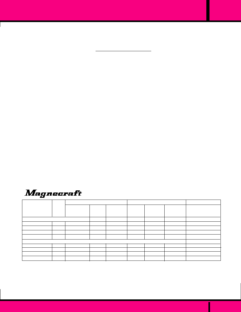
230
NO
NO
W230E Models: 1.5 Amps, W230T Models: 3 Amps
120 VAC or 240 VAC
140 VAC or 280 VAC
120V Models: 400 VAC, 240V Models: 500 VAC
20 mA @ 25�C
1.0 mA max.
1.7 V
200V/uSec
SPST-NO
2500 VAC
10
10
-30
�
C to +80
�
C
-40
�
C to +100
�
C
Greater than 100 million operations
P.C.
0.37 oz. (10.6 g)
Reverse Polarity Protected:
Input Filtered for transients less than one millisecond.:
Rated Load Current: I
T
(RMS):
Line Voltage Range (VAC):
Maximum output voltage (VAC):
Non-Repetitive Peak Voltage V
DSM
(Blocking Voltage):
Minimum Load Current I
T MIN
(RMS) to maintain "On":
Maximum Off State Leakage current I
D
(RMS):
Maximum RMS On-State Voltage V
T
(RMS)
@ rated current:
Maximum rate of rise off-state voltage dv/dt:
Contact configuration:
Dielectric Strength V
ISO
(Input-Output Isolation):
Insulation Resistance R
ISO
@ 500VDC:
Operating temperature Range:
Storage temperature Range:
Life:
Mounting
Weight:
INPUT CHARACTERISTICS
OUTPUT CHARACTERISTICS
MISCELLANEOUS
SPECIFICATIONS CLASS 230
MINIATURE P.C. SOLID STATE RELAY
All current ratings are based on use of suitable thermally conductive compound (e.g. silicone grease between the
SSR mounting base and mounting surface of suitable heat sink).
PART
NUMBERS
W230E-1-5
W230E-2-5
W230E-1-12
W230E-2-12
W230T-3-5
W230T-4-5
W230T-3-12
W230T-4-12
PRINTED CIRCUIT TERMINALS
NOMINAL
VOLTAGE
OUTPUT
CURRENT
MAX.
VOLTAGE
MAX.
PULL-IN
VOLTAGE
MIN.
DROPOUT
VOLTAGE
0UTPUT
(Over Operating Temperature Range)
INPUT
(Over Operating Temperature Range)
120 VAC
240 VAC
120 VAC
240 VAC
120 VAC
240 VAC
120 VAC
240 VAC
4.0 VDC
4.0 VDC
9.3 VDC
9.3 VDC
4.0 VDC
4.0 VDC
9.3 VDC
9.3 VDC
2.0 VDC
2.0 VDC
2.0 VDC
2.0 VDC
2.0 VDC
2.0 VDC
2.0 VDC
2.0 VDC
140 VAC
280 VAC
140 VAC
280 VAC
140 VAC
280 VAC
140 VAC
280VAC
1.5 AMPS
1.5 AMPS
1.5 AMPS
1.5 AMPS
3 AMPS
3 AMPS
3 AMPS
3 AMPS
INPUT
VOLTAGE
FIGURE
A
A
A
A
B
B
B
B
5 VDC
5 VDC
12 VDC
12 VDC
5 VDC
5 VDC
12 VDC
12 VDC
MOLEX
02-06-1103
02-06-1132
WINCHESTER
156-10185
156-10245
PUSH-0N TERMINAL RECEPTACLES
FOR 18-22 AWG
FOR 24-30
Part Numbers shown also available thru Stocking Distribution.
PRINTED CIRCUIT TERMINALS WITH HEAT SINK
CROSS REFERENCE
CP CLARE/ THETA-J
0FA1202
0FA2402
0FB1202
0FB2402
0FA1205D
0FA2405D
0FB1205D
0FB2405D
C L A S S
WEBSITE: www.magnecraft.com - EMAIL:info@magnecraft.com - FAX ON DEMAND 1-800/891-2957 - DOCUMENT 100
PAGE 100

MINIATURE SOLID STATE RELAY
C L A S S
13mA typical / 16 mA max.
1/2 Cycle
200V/uSec blocking 10V/uSec commutating
4 Amperes
1 mA @ 25�C
20 Amperes
5 Amperes
4.5 Amperes
6�c/w
OUTPUT CHARACTERISTICS
INPUT CHARACTERISTICS
Input Impedance (Current @ Nominal Voltage)
Response Time
Maximum Rate of Rise of Off State Voltage dv/dt
Rated Load Current (Amps rms)
Maximum off State Leakage current I
D
(RMS)
Non-Repetitive Surge Current one Cycle (Amps peak)
Maximum rms Overload current for 1 second
Max I
2
T For Fusing ( t= 8-3ms) A
2
sec
Thermal Resistance Junction To Case (T
J
, Max.= 115
0
C)
0
c/w
120 VAC or 240 VAC
5 or 12 VDC
UL Recognized
File No. E52197
1.40
(35.5)
1.19
(30.2)
1
2
3
.860
(21.8)
.600 Max
(15.24)
.078 R
(1.98)
.860
(21.8)
.595
(15.1)
+
-
AC
AC
LOAD
Top View
4
.250
(6.3)
.250 x .032 Typ.
(6.3) x .81
.187 x .032 Typ.
(4.7) x .81
INPUT
.340 Max
(8.6)
CLASS 231
4 AMPS
SPST--NO
DC INPUTS,
AC OUTPUTS
ZERO VOLTAGE
SWITCHING.
Dimensions Shown in Inches & (Millimeters)
,048 Max
(1.2)
231
THE W231 SSR HAS THE SAME ELECTRICAL SPECIFICATIONS AS LISTED FOR THE W230 SSR's. THE EXCEPTION IS
THE CLASS W231 IS RATED AT 4.0 AMPS.
PART
NUMBERS
W231D-3-5
W231D-4-5
W231D-3-12
W231D-4-12
FLANGE MOUNT
NOMINAL
VOLTAGE
OUTPUT
CURRENT
MAX.
VOLTAGE
MAX.
PULL-IN
VOLTAGE
MIN.
DROPOUT
VOLTAGE
0UTPUT
(Over Operating Temperature Range)
INPUT
(Over Operating Temperature Range)
120 VAC
240 VAC
120 VAC
240 VAC
4.0 VDC
4.0 VDC
9.3 VDC
9.3 VDC
2.0 VDC
2.0 VDC
2.0 VDC
2.0 VDC
140 VAC
280 VAC
140 VAC
280 VAC
4 AMPS
4 AMPS
4 AMPS
4 AMPS
INPUT
VOLTAGE
5 VDC
5 VDC
12 VDC
12 VDC
QUICK DISCONNECT TERMINALS
WITH .060 DIA. HOLES
TERMINALS 1 & 2, .250 X .032 BRASS
TERMINALS 3 & 4, .187 X .032 BRASS
All current ratings are based on use of suitable thermally conductive compound (e.g. silicone grease between the
SSR mounting base and mounting surface of suitable heat sink).
Mounting: TO-3 Style.
Weight: .57oz. (16.2 grams).
Part Numbers shown also available thru Stocking Distribution.
CROSS REFERENCE
CP CLARE/ THETA-J
0FA1205
0FA2405
0FB1205
0FB2405
WEBSITE: www.magnecraft.com - EMAIL:info@magnecraft.com - FAX ON DEMAND 1-800/891-2957 - DOCUMENT 100
PAGE 101

SPECIFICATIONS SOLID STATE RELAY
25
40
30
35
20
15
10
5
0
1000
500
200
100
50
20
10
5
2
Non- Repetitive Surge RMS Amps
.01 .02 .05 0.1 0.2 0.5 1.0 2.0 5.0 10.0
1
75 Amps
10 Amps
2.5 Amps
25 Amps
40 Amps
Time in Seconds
Surge: Curves represent relay tolerance to load
surge currents as to magnitude and duration of
both repetitive and non-repetitive surge currents.
SURGE: OUTPUT 120 & 240 VAC
2.25
(57.2)
1.87
(47.5)
1.00
(25.4)
0.37
(9.4)
0.32
(8.1)
Dimensions shown in Inch and (Millimeter).
0.19
(4.8)
OUTPUT
INPUT
RED
L.E.D.
.175 Dia. (4.44)
(2 Holes)
1.75
(44.45)
1.10
(27.9)
1.75
(44.5)
.215
(5.46)
OUTLINE DIMENSIONS
Input Voltage (Volts)
1
2
3
4
.49 Typ.
(12.5)
Clamping Plate
4 Places
(Not used on models .996 high)
.265 max.
(6.73)
.996 max. (25.3) for 25 & 40 amp DDX models & for 75
Amp DSX & ASX models.
.800 max (20.32) for models ASX, DSX & DTX models up
to 40 Amps & DDX 12 Amp models.
UP TO 40 AMP
INPUT
OUTPUT
3.5 mm
ABOVE 40 AMP
INPUT & OUTPUT SCREW SIZE
(Shown in Millimeters)
6 mm
3.5 mm
4 mm
OUTPUT
SEE CHART
C L A S S
6
INPUT
Recognized to Canadian safety
requirements under the Component
Recognition Program of Underwriters
Laboratories Inc.
N E W !
N E W !
N E W !
N E W !
N E W !
L.E.D. "ON" LAMP
UL Recognized
File No. E52197
INPUT
TERMINALS
HIGH
DV/DT
RATING
CLASS 6 SSR
RUGGED
CONSTRUCTION
OUTPUT
TERMINALS
10 20 30 DC Input Models
100 200 300 AC Input Models
AC INPUT
DC INPUT
CLASS 6
TYPICAL INPUT CURRENT
Input Current (mA)
PAGE 102
WEBSITE: www.magnecraft.com - EMAIL:info@magnecraft.com - FAX ON DEMAND 1-800/891-2957 - DOCUMENT 100

C L A S S
GENERAL SPECIFICATIONS
SPECIFICATIONS CLASS 6 SOLID STATE RELAYS
6
OUTPUT CHARACTERISTICS
MISCELLANEOUS CHARACTERISTICS
INPUT CHARACTERISTICS
Input voltage range:
Power indicator:
Reverse Polarity Protected:
Input Filtered for transients less than one millisecond.:
Control current:
Contact rating:
Line Voltage Range (VAC)
Maximum output voltage (VAC):
Non-Repetitive Peak Voltage V
DSM
(Blocking Voltage)
Minimum Load Current I
T MIN
(RMS) to maintain "On"
Maximum Off State Leakage current I
D
(RMS)
Maximum RMS On-State Voltage V
T
(RMS) Maximum
Voltage drop across relay output @ rated current:
Minimum off-state dv/dt:
Contact configuration:
Dielectric Strength V
ISO
(Input-Output Isolation)
Insulation Resistance R
ISO
@ 500VDC
Operating temperature Range
Storage temperature Range
Life:
Weight
3-32 VDC, 90-280 VAC or 0 to 200VDC
L.E.D. Lamp
YES: DC Input with AC output styles only.
No
12 mA @ 5Vdc, 10 mA @ 120 Vac
2 Amps to 75 Amps
W61 Models: 24-120VAC, W62 Models: 40-240 VAC
W61: 140VAC, W62: 280 VAC
W61: 300VAC , W62: 600VAC
Up to 40 amp Models: 50 ma, 50 to 75 Amp models: 250mA
Up to 40 amp Models: 8 mA, 50 to 75 Amp models: 10mA
Up to 40 amp Models: 1.6V, 50 to 75 Amp models: 1.8 V
500v/usec
SPST-NO (1 FORM A)
4000 VAC, DDX models 2500 VAC
10
10
-40
�
C to +80
�
C
-40
�
C to +100
�
C
Greater than 100 million operations
2.5 to 50 AMP Models: 4 oz. (110 g)
75 AMP Models: 6.8 oz. (192 g)
25 AMP & 40 AMP, DDX Models: 4.76 oz. (135 g)
20
0
10 20 30 40 50 60 70 80
-90
-95
-100
-105
-110
0
10
30
40
45
60
75
20 40 60 80 100
Max. Ambient Temperature (�C)
Load Current (Amps RMS)
50
90
70
80
40
30
20
0
Mounted on Heat Sink with 1�c/w
thermal resistance.
Free Air Mounting
10
6" x 6" x 1/8"
Aluminum Plate
75 Amp Styles
Load Current (Amps RMS)
Max. Allowable Case temperature (�c)
Max. Ambient Temperature (�C)
6" x 6" x 1/8"
Aluminum Plate
0
3
1
2
20 40 60 80 100
Max. Ambient Temperature (�C)
Load Current (Amps RMS)
Free Air Mounting
2.5 Amp Style
20 40 60 80 100
Load Current (Amps RMS)
0
10
14
16
8
6
4
2
12
Free Air Mounting
Heat Sink
with
1�c/w
thermal
resistance.
10 Amp Styles
20 40 60 80 100
25
40
30
35
20
15
10
5
0
Free Air Mounting
25 Amp Styles
6" x 6" x 1/8" Aluminum Plate
6" x 6" x 1/8" Aluminum Plate
Mounted on Heat Sink with 1�c/w
thermal resistance.
(Sink to Ambient)
6" x 6" x 1/8"
Aluminum
Plate
Max. Ambient Temperature (�C)
Load Current (Amps RMS)
Max. Ambient Temperature (�C)
Thermal Derating Curve & Load Characteristics
All current ratings in the following pages are based on use of suitable thermally conductive compound (e.g. silicone grease
between the SSR mounting base and mounting surface of suitable heat sink).
40 & 50 Amp Styles
PAGE 103
WEBSITE: www.magnecraft.com - EMAIL:info@magnecraft.com - FAX ON DEMAND 1-800/891-2957 - DOCUMENT 100

W6110DTX-1
W6210DTX-1
CONTROL
VOLTAGE
RANGE
24-120AC
48-240AC
3-32 VDC
3-32 VDC
3 VDC
3 VDC
1 VDC
1 VDC
MAX.
VOLTAGE
140 VAC
280 VAC
10 AMPS
10 AMPS
IDEC
CRYDOM
POTTER &
BRUMFIELD
MAX.
PULL-IN
VOLTAGE
MIN.
DROPOUT
VOLTAGE
TD1210
TD2410
PART
NUMBERS
CROSS REFERENCE TO:
0UTPUT
(Over Operating Temperature Range)
INPUT
(Over Operating Temperature Range)
-
-
SSRT120D10
SSRT240D10
All current ratings are based on use of suitable thermally conductive compound (e.g. silicone grease between the SSR mounting base and mounting
surface of suitable heat sink).
Part Numbers shown also available thru stocking distribution.
OUTPUT CHARACTERISTICS
INPUT CHARACTERISTICS
Input Impedance
Response Time
Maximum Rate of Rise of Off State Voltage dv/dt
Rated Load Current (Amps rms)
U/L Incandescent Lamp Ampere Ratings
U/L Motor Load Ampere Ratings
Non-Repetitive Surge Current one Cycle (Amps peak)
Maximum rms Overload current for 1 second
Max I
2
T For Fusing ( t= 8-3ms) A
2
sec
Thermal Resistance Junction To Case (T
J
, Max.= 115
0
C)
0
c/w
1500 ohms minimum
1/2 Cycle Max.
200 Volts per microsecond
3 to 32 VDC
10.0
7.0
4.5
100
24
42
2.1
120 or 240 VAC
High Transient Capability--Single output
features back to back SCR's and internally
mounted RC (snubber) network for high dv/dt
applications.
Photo-Isolated, Zero Voltage Switching--
Optically coupled for 4000 VAC isolation
between input and output and RFI suppression.
Recognized to Canadian safety
requirements under the Component
Recognition Program of Underwriters
Laboratories Inc.
UL Recognized
File No. E52197
CLASS 6
DC CONTROLLED INPUT
WITH L.E.D. "ON" LAMP.
AC TRIAC OUTPUT.
NOMINAL
VOLTAGE
RANGE
6
C L A S S
DC CONTROLLED INPUT TRIAC OUTPUT SSR
MAX.
CURRENT
RATING
N E W !
N E W !
N E W !
N E W !
N E W !
L.E.D. "ON" LAMP
SEE CLASS 6 GENERAL SPECIFICATIONS
WEBSITE: www.magnecraft.com - EMAIL:info@magnecraft.com - FAX ON DEMAND 1-800/891-2957 - DOCUMENT 100
PAGE 104
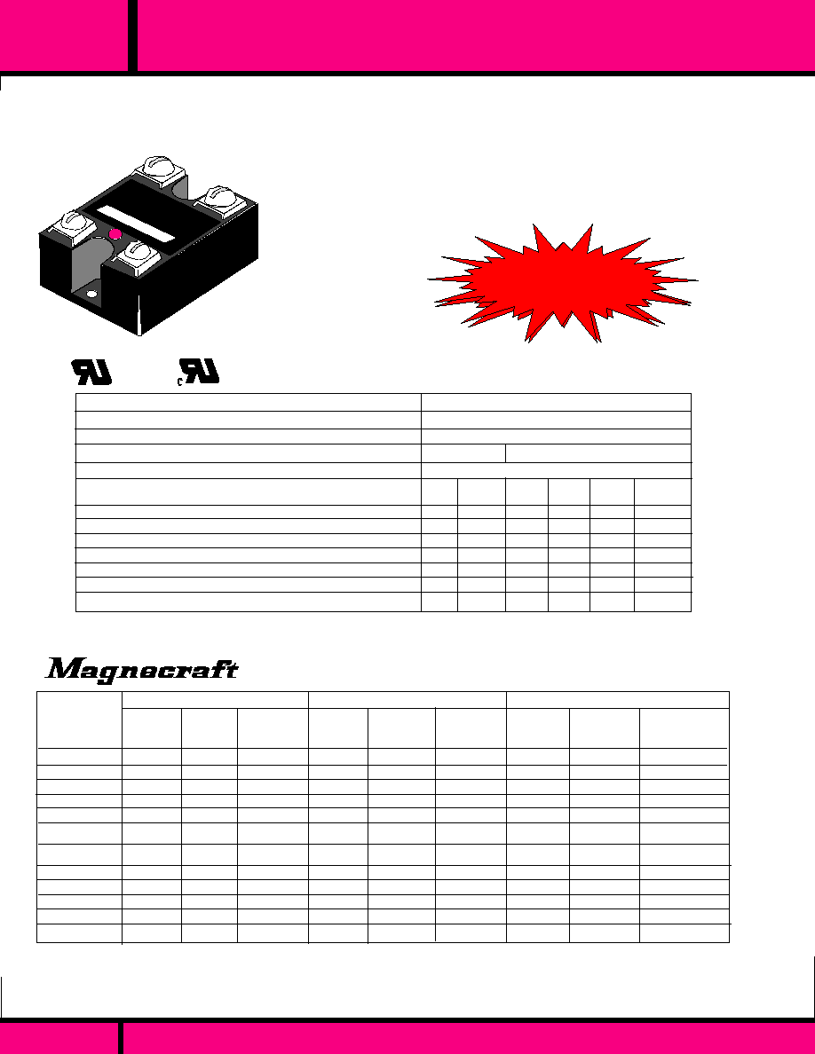
DC CONTROLLED SOLID STATE RELAY
CLASS 6
DC CONTROLLED INPUT
WITH L.E.D. "ON" LAMP.
AC SCR OUTPUTS UP
TO 75 AMPS.
High Transient Capability--Single out-
put features back to back SCR's an
internal mounted RC (snubber) network
for high dv/dt applications.
Photo-Isolated, Zero Voltage Switching--
Optically coupled for 4000 VAC isolation
between input, output and RFI suppression.
W6102DSX-1
W6110DSX-1
W6125DSX-1
W6140DSX-1
W6150DSX-1
W6175DSX-1
W6202DSX-1
W6210DSX-1
W6225DSX-1
W6240DSX-1
W6250DSX-1
W6275DSX-1
CONTROL
VOLTAGE
RANGE
24-120AC
24-120AC
24-120AC
24-120AC
24-120AC
24-120AC
48-240AC
48-240AC
48-240AC
48-240AC
48-240AC
48-240AC
3-32 VDC
3-32 VDC
3-32 VDC
3-32 VDC
3-32 VDC
3-32 VDC
3-32 VDC
3-32 VDC
3-32 VDC
3-32 VDC
3-32 VDC
3-32 VDC
3 VDC
3 VDC
3 VDC
3 VDC
3 VDC
3 VDC
3 VDC
3 VDC
3 VDC
3 VDC
3 VDC
3 VDC
1 VDC
1 VDC
1 VDC
1 VDC
1 VDC
1 VDC
1 VDC
1 VDC
1 VDC
1 VDC
1 VDC
1 VDC
MAX.
VOLTAGE
140 VAC
140 VAC
140 VAC
140 VAC
140VAC
140VAC
280 VAC
280 VAC
280 VAC
280 VAC
280 VAC
280 VAC
2.5 AMPS
10 AMPS
25 AMPS
40 AMPS
50 AMPS
75 AMPS
2.5 AMPS
10 AMPS
25 AMPS
40 AMPS
50 AMPS
75 AMPS
IDEC
CRYDOM
POTTER &
BRUMFIELD
MAX.
PULL-IN
VOLTAGE
MIN.
DROPOUT
VOLTAGE
D1202
D1210
D1225
D1240
D2402
D2410
D2425
D2440
D2450
D2475
PART
NUMBERS
CROSS REFERENCE TO:
0UTPUT
(Over Operating Temperature Range)
INPUT
(Over Operating Temperature Range)
-
RSSD-10A
RSSD-25A
RSSD-40A
RSSD-50A
RSSD-75A
-
RSSD-10A
RSSD-25A
RSSD-40A
RSSD-50A
RSSD-75A
All current ratings are based on use of suitable thermally conductive compound (e.g. silicone grease between the SSR mounting base and mounting
surface of suitable heat sink).
Part Numbers shown also available thru stocking distribution.
EOM1DA22-4-32
EOM1DA42-4-32
SSR240D25
-
SSR240D50
SSR240D80
-
EOM1DA44-4-32
SSR240D25
-
SSR240D50
SSR240D80
OUTPUT CHARACTERISTICS
INPUT CHARACTERISTICS
Input Impedance
Response Time
Maximum Rate of Rise of Off State Voltage dv/dt
Rated Load Current (Amps rms)
U/L Incandescent Lamp Ampere Ratings
U/L Motor Load Ampere Ratings
Non-Repetitive Surge Current one Cycle (Amps peak)
Maximum rms Overload current for 1 second
Max I
2
T For Fusing ( t= 8-3ms) A
2
sec
Thermal Resistance Junction To Case (T
J
, Max.= 115
0
C)
0
c/w
Minimum Load current, (mA).
2.5 10 25 40 50 75
2.0 8.0 16 30 30 39
1.0 4.5 8 14 14 25
100 100 250 350 350 1150
5 24 40 80 100 150
72 72 800 1250 1250 5000
8.5 1.78 1.02 0.63 0.63 0.63
50 50 120 250 250 250
400 ohms @ 3 VDC Typical
1/2 Cycle Max.
200 500 Volts per microsecond
3 to 32 VDC
N E W !
N E W !
N E W !
N E W !
N E W !
L.E.D. "ON" LAMP
Recognized to Canadian safety
requirements under the Component
Recognition Program of Underwriters
Laboratories Inc.
UL Recognized
File No. E52197
C L A S S
6
NOMINAL
VOLTAGE
RANGE
NAX.
CURRENT
RATING
120 VAC or 240 VAC
SEE CLASS 6 GENERAL SPECIFICATIONS
PAGE 105
WEBSITE: www.magnecraft.com - EMAIL:info@magnecraft.com - FAX ON DEMAND 1-800/891-2957 - DOCUMENT 100
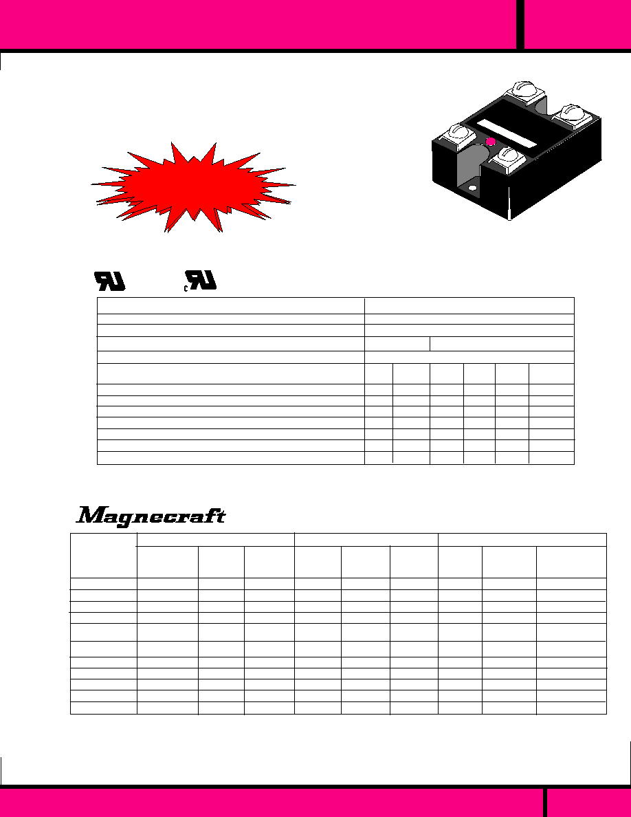
N E W !
N E W !
N E W !
N E W !
N E W !
L.E.D. "ON" LAMP
C L A S S
6
AC CONTROLLED SOLID STATE RELAY
CLASS 6
AC CONTROLLED INPUT
WITH L.E.D. "ON LAMP"
AC SCR OUTPUT.
High Transient Capability--Single output
features back to back SCR's and internally
mounted RC (snubber) network for high dv/dt
applications.
Photo-Isolated, Zero Voltage Switching--
Optically coupled for 4000 VAC isolation
between input and output and RFI suppression.
IDEC
POTTER &
BRUMFIELD
PART
NUMBERS
CROSS REFERENCE TO:
-
SSR240A25
-
SSR240A50
SSR240A80
-
-
SSR240A25
-
SSR240A50
SSR240A80
OUTPUT CHARACTERISTICS
Rated Load Current (Amps rms)
U/L Incandescent Lamp Ampere Ratings
U/L Motor Load Ampere Ratings
Non-Repetitive Surge Current one Cycle surge (Amps peak)
Maximum rms Overload current for 1 second
Max I
2
T For Fusing ( t= 8-3ms) A
2
sec
Thermal Resistance Junction To Case (T
J
, Max.= 115
0
C)
0
c/w
Minimum Load current, (mA):
2.5 10 25 40 50 75
2.0 8.0 16 30 30 39
1.0 4.5 8.0 14 14 25
100 100 250 350 350 1150
5 24 40 80 100 150
72 72 800 1250 1250 5000
8.5 1.48 1.02 0.63 0.63 0.63
50 50 120 120 120 120
W6110ASX-1
W6125ASX-1
W6140ASX-1
W6150ASX-1
W6175ASX-1
W6202ASX-1
W6210ASX-1
W6225ASX-1
W6240ASX-1
W6250ASX-1
W6275ASX-1
CRYDOM
10 AMPS
25 AMPS
40 AMPS
50 AMPS
75 AMPS
2.5 AMPS
10 AMPS
25 AMPS
40 AMPS
50 AMPS
75 AMPS
MAX.
VOLTAGE
140 VAC
140 VAC
140 VAC
140 VAC
140VAC
280 VAC
280 VAC
280 VAC
280 VAC
280 VAC
280 VAC
0UTPUT
(Over Operating Temperature Range)
INPUT
(Over Operating Temperature Range)
10 VAC
10 VAC
10 VAC
10 VAC
10 VAC
10 VAC
10 VAC
10 VAC
10 VAC
10 VAC
10 VAC
90 VAC
90 VAC
90 VAC
90 VAC
90 VAC
90 VAC
90 VAC
90 VAC
90 VAC
90 VAC
90 VAC
90 -280 VAC
90 -280 VAC
90 -280 VAC
90 -280 VAC
90 -280 VAC
90 -280 VAC
90 -280 VAC
90 -280 VAC
90 -280 VAC
90 -280 VAC
90 -280 VAC
Part Numbers shown also available thru stocking distribution.
All current ratings are based on use of suitable thermally conductive compound (e.g. silicone grease between the SSR mounting base
and mounting surface of suitable heat sink).
CONTROL
VOLTAGE
RANGE
MIN.
DROPOUT
VOLTAGE
MAX.
PULL-IN
VOLTAGE
INPUT CHARACTERISTICS
Input Impedance
Response Time
Maximum Rate of Rise of Off State Voltage dv/dt
90 to 280 VAC or 80 to 140 VDC
13K ohms @ 120VAC typical
10 mS Turn ON, 40 mS Turn OFF.
200 500 Volts per microsecond
RSSAN-10A
RSSAN-25A
RSSAN-40A
RSSAN-50A
RSSAN-75A
-
RSSAN-10A
RSSAN-25A
RSSAN-40A
RSSAN-50A
RSSAN-75A
A1210
A1225
A1240
A1250
A1275
A2402
A2410
A2425
A2440
A2450
A2475
Recognized to Canadian safety
requirements under the Component
Recognition Program of Underwriters
Laboratories Inc.
UL Recognized
File No. E52197
NOMINAL
VOLTAGE
RANGE
24-120AC
24-120AC
24-120AC
24-120AC
24-120AC
48-240AC
48-240AC
48-240AC
48-240AC
48-240AC
48-240AC
MAX.
CURRENT
RATING
120 VAC or 240 VAC
SEE CLASS 6 GENERAL SPECIFICATIONS
PAGE 106
WEBSITE: www.magnecraft.com - EMAIL:info@magnecraft.com - FAX ON DEMAND 1-800/891-2957 - DOCUMENT 100

DC CONTROLLED INPUT DC OUTPUT
CLASS 6
DC CONTROLLED INPUT
DC OUTPUT
Transformer-Isolated, for 2500 VAC isolation
between input and output and RFI suppression.
OUTPUT CHARACTERISTICS
INPUT CHARACTERISTICS
Input Impedance
Response Time
Maximum Rate of Rise of Off State Voltage dv/dt
Rated Load Current (Amps rms)
Minimum Load current to maintain "On"
Non-Repetitive Surge Current (1 cycle surge)
FW rectified current repetitive 60 Hz Amps peak
Voltage drop across output @ rated current
Max I
2
T For Fusing ( t= 8-3ms) A
2
sec
Thermal Resistance Junction To Case
0
c/w
Max. off state leakage current:
12.0
20 mA
27
17
2.83
2.1
1.06
12 mA
3.5 to 32 VDC
0 to 200 VDC
1000 ohms minimum
100 uS: On, 1.0 mS: Off 600 uS: On, 2.6 mS Off
200 Volts per microsecond
25
20 mA
50
-
2.83
2.1
1.06
12 mA
40
20 mA
90
-
2.83
2.1
1.06
12 mA
SEE COMPLETE SPECIFICATIONS PAGES 83 & 84
CONTROL
VOLTAGE
RANGE
INPUT
(Over Operating Temperature Range)
W6212DDX-1
W6225DDX-1
W6240DDX-1
MIN.
DROPOUT
VOLTAGE
1 VDC
1 VDC
1 VDC
3.5 VDC
3.5 VDC
3.5 VDC
MAX.
PULL-IN
VOLTAGE
3.5 - 32 VDC
3.5 - 32 VDC
3.5 - 32 VDC
Part Numbers shown also available thru stocking distribution.
All current ratings are based on use of suitable thermally conductive compound (e.g. silicone grease between the SSR
mounting base and mounting surface of suitable heat sink).
0 -200 VDC
0 -200 VDC
0 -200 VDC
12 AMPS
25 AMPS
40 AMPS
0UTPUT
(Over Operating Temperature Range)
PART
NUMBERS
*
Crydom relays only rated at 0 - 100 VDC.
CROSS REFERENCE
CRYDOM
D2D12
D1D20
*
D1D40
*
N E W !
N E W !
N E W !
N E W !
N E W !
L.E.D. "ON" LAMP
Recognized to Canadian safety
requirements under the Component
Recognition Program of Underwriters
Laboratories Inc.
UL Recognized
File No. E52197
PAGE 107
NOMINAL
VOLTAGE
RANGE
MAX.
CURRENT
RATING
C L A S S
6
WEBSITE: www.magnecraft.com - EMAIL:info@magnecraft.com - FAX ON DEMAND 1-800/891-2957 - DOCUMENT 100
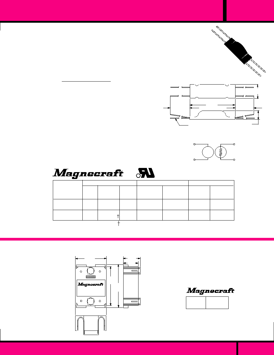
C L A S S
301T OPTO-ISOLATOR
301T OPTO-ISOLATOR
0.2 WATT OUTPUT
VAC OR VDC OUTPUTS
OPTICAL COUPLING PROVIDES HIGH
INPUT TO OUTPUT ISOLATION.
CAN BE USED AS AN ON/OFF
SWITCH OR LOW VOLTAGE
CONTROLLED RESISTOR. IDEAL
FOR TRIGGERING SCR'S AND TRIACS.
L
PC
1.40 Max.
(35.6)
1.00
�
.125
(25.4
�
3.17)
1.00
�
.125
(25.4
�
3.17)
.438
(11.1)
.45 Max
(11.4)
# 26 AWG
Typical
Shrink Tube Case
CONTACTS
Output Voltage Max:.
INSULATION RESISTANCE
Dielectric Strength
Across Open Contacts:
Insulation Resistance:
ENVIRONMENTAL CAPABILITIES
Ambient Temperature
Operating:
Miscellaneous
Weight:
SPECIFICATIONS 301T
PC
Lamp
+
If DC
L
SCHEMATIC
LAMP
TYPE
VOLTAGE
TURN-ON
TO 10K
(mS max.)
TURN-OFF
TO 100K
(mS max.)
OUTPUT
RESPONSE TIME
INPUT
LED
LED
INCAND.
NEON
1.7 VDC
2.0 VDC
12 VDC/AC
120 VDC/AC
ON
RESISTANCE
(Ohms max.)
POWER
DISSIPATION
Per pole (mW)
2000
1000
400
1200
200
200
200
200
10
5
150
35
50
100
300
100
CURRENT
(mA)
Add 47K
Ohm external series resistor to limit current.
R
PART
NUMBERS
PART NUMBERS SHOWN ALSO AVAILABLE THRU STOCKING DISTRIBUTION.
W301T1-2A1
W301T1-2B1
W301T1-12B1
W301T1-120A1
40
25
24
1.3
EMBOSSED SAFETY COVER
CLEAR COVER FOR CLASS 6
SOLID STATE RELAYS
PREVENTS ELECTRICAL
SHOCK HAZARDS FROM
EXPOSED TERMINALS.
PART
NUMBER
15-700
OUTLINE DIMENSIONS
NOT SUPPLIED WITH RELAY. TO
BE ORDERED SEPARATELY IF
REQUIRED.
Weight:: 0.476 oz. (13.5 g)
�
250 VDC or VAC Peak
1000 V rms Between all insulated Points
10
9
Ohms
-40�C to + 60�C
0.04 oz (1.1 g)
NOT RECOMENDED FOR WAVE OR DIP
SOLDERING. ALSO MAY BE AFFECTED
BY CLEANING SOLVENTS
UL Recognized
File No. E104675
SSR
PAGE 108
WEBSITE: www.magnecraft.com - EMAIL:info@magnecraft.com - FAX ON DEMAND 1-800/891-2957 - DOCUMENT 100
1.93 Max.
(49.2)
1.04 Max
(26.5)
.812
(20.6)
2.65
(67.4)
2.45
(62.3)
OUTLINE DIMENSIONS

TIME DELAY RELAYS
AND
SENSORS
5 TO 13 AMPERES
5
S E C T I O N
5
Page 109

TIME DELAY RELAYS
FEATURES
CONTACT DATA
COIL DATA
GENERAL DATA
DIMENSIONS
APPROVALS
AC - VOLTAGE:
DC - VOLTAGE:
INPUT VOLTAGE RANGE
REVERSE POLARITY
PROTECTION:
INSULATION
CHARACTERISTICS
DIELECTRIC STRENGTH:
AMBIENT TEMPERATURE
OPERATIONAL:
STORAGE:
TIMING VALUES
OPERATE MAX.:
RELEASE MAX:
LIFE
ELECTRICAL @ rated Load:
MECHANICAL:
CONTACT CONFIGURATION:
CONTACT RATING:
CONTACT MATERIAL
CONTACT RESISTANCE:
H W L
1.18 X .734 X 1.37
Silver, Gold Overlay
50 Milliohms
Max. Initial
1250 V rms
- 30� C to + 80� C
- 40� C to + 100� C
0.1 to 30 Seconds
-
50,000 Operations
50,000,000 Operations
AC On Special Order
12 & 24 VDC
DC - 10 to 14, 20 to 32
DC MODELS ONLY
DPDT
5AMPS @
120 VAC, 28 VDC
MINIATURE PLUG-IN
"ON DELAY"
REPEATABILITY
�
2%
FIELD ADJUSTABLE
BY SCREW DRIVER
4 POLE STYLES AVAIL-
ABLE
P.C. TERMINALS
AVAILABLE..
H W L
.1.75 X 2.37 X 3.49
120 VAC
DC - SPECIAL ORDER
90 to 130 VAC
DC MODELS ONLY
DPDT
10 AMPS,
120VAC, 28 VDC
8 PIN OCTAL PLUG-IN
REPEAT CYCLE ON &
OFF DELAY
�
0.1 % REPEATABILITY
FIELD ADJUSTABLE
TIMING USING KNOBS.
1500 V rms
Silver cadimum Oxide
50 MILLIOHMS
Max Initial
- 30� C to + 55� C
- 55� C to + 85� C
0.1 Second to 30 Minutes
0.1 Second to 30 Minutes
200,000 Operations
50,000,000 Operations
WEBSITE: www.magnecraft.com EMAIL:info@magnecraft.com FAX ON DEMAND 1-800/891-2957, DOCUMENT 100
PAGE 110
222
67
RELAY CLASS/SERIES
H W L
Silver Cadmium Oxide
50 MILLIOHMS
Max. Initial
1500 V rms
1.75 X 2..37 X 3.5"
120 VAC
24 VDC
AC - 90 to 130
DC - 20 to 32
DC MODELS ONLY
DPDT
10 AMPS @
120 VAC, 30VDC
8 or 11 PIN OCTAL
PLUG-IN.
"ON DELAY" OR
OFF DELAY"
REPEATABILITY
�
0.1%
FIELD ADJUSTABLE
BY KNOB
INTERVAL, FLASHER,
ONE SHOT OR ON
& OFF DELAY AVAILABLE
211
PAGE 113, 114
H W L
Silver Cadmium Oxide
50 MILLIOHMS
Max. Initial
1500 V rms
1.75 X 2..37 X 3.5"
120/24 VAC
24 VDC
AC - 90 to 130
DC - 20 to 32
DC MODELS ONLY
DPDT
10 AMPS @
120 VAC, 30VDC
8 or 11 PIN OCTAL
PLUG-IN.
4 PROGRAMMABLE
FUNCTIONS
62 PROGRAMMABLE
TIMING RANGES
4 INPUT VOLTAGE
RANGES
REPEATABILITY
�
0.1%
FIELD ADJUSTABLE
BY KNOB & DIP SWITCH
211 PROG
- 30� C to + 55� C
- 55� C to + 85� C
AS SELECTED
AS SELECTED
200,000 Operations
50,000,000 Operations
- 30� C to + 55� C
- 55� C to + 85� C
0.1 Seconds to 120 Minutes
0.1 Seconds to 15 Minutes
200,000 Operations
50,000,000 Operations
PAGE NUMBER
APPLICATION DATA:
PAGE 115, 116
PAGE 117
PAGE 118
PAGE 119
Magnecraft
Struthers-Dunn

PAGE
91
H W L
24 to 240VAC
12 to 115-125 VDC
85% Of Nominal
80% Of Nominal
DC MODELS ONLY
SPDT, DPDT, 3PDT
10 AMPS @
120/240 VAC, 28 VDC
Silver Cadimum Oxide
50 MILLIOHMS
Max.initial
1500 V rms
H W L
- 10� C to + 70� C
-
0.1 to 300 Seconds
100,000 Operations
10,000,000 Operations
H W L
PAGE 124
H W L
1.40 X 1.53 X 3.52
120 VAC
24 VDC
90 to 130 VAC
20 to 32 VDC
DC MODELS ONLY
SQUARE BASE PLUG-IN
OFF DELAY
�
3 % REPEATABILITY
FIELD ADJUSTABLE
TIMING USING KNOB.
POWER TO INPUT NOT
REQUIRED DURING
TIMING CYCLE.
Silver Cadimum Oxide
50 MILLIOHMS
Max.initial
2000 V rms
DPDT
12 AMPS @
120 VAC, 28 VDC
- 10� C to + 55� C
- 55� C to + 85� C
-
0.6 to 60 Seconds
100,000 Operations
5,000,000 Operations
H W L
Silver cadimum Oxide
50 MILLIOHMS
Max Initial
120 VAC
24 VDC
90 to 130 VAC
20 to 32 VDC
DC MODELS ONLY
DPDT
12 AMPS,
120VAC, 28 VDC
1.40 X 1.53 X 3.52 LG.
1.40 X 1.53 X 3.02 MED.
- 30� C to + 55� C
- 55� C to + 85� C
0.1 to 120 Seconds
1.0 to 180 Seconds
100,000 Operations
5,000,000 Operations
SQUARE BASE PLUG-IN
ON DELAY OR
OFF DELAY
�
0.1 % REPEATABILITY
FIELD ADJUSTABLE
TIMING USING KNOB.
INTERVAL, FLASHER,
ONE SHOT OR ON
& OFF DELAY AVAILABLE
2000 V rms
RETANGULAR PLUG-IN
286 -ON DELAY, 287 -
0FF DELAY
�
3 % REPEATABILITY
TIMING FIELD ADJUST-
ABLE BY KNOB OR
EXTERNAL RESISTOR.
1, 2 & 3 POLE 10 AMP
SWITCHING.
Silver cadimum Oxide
50 MILLIOHMS
Max Initial
1.40 X 1.53 X 1.90
- 30� C to + 55� C
- 55� C to + 85� C
0.1 to 120 Seconds
0.1 to 120 Seconds
100,000 Operations
5,000,000 Operations
120 VAC
24 VDC
90 to 130 VAC
20 to 32 VDC
DC MODELS ONLY
SQUARE BASE PLUG-IN
OR FLANGE MOUNT
ON DELAY OR
OFF DELAY
�
3 % REPEATABILITY
FIELD ADJUSTABLE
TIMING USING EXTER-
NAL RESISTOR
H W L
DPDT
12 AMPS,
120VAC, 28 VDC
1500 V rms
PAGE 122, 123
PAGE 120, 121
PAGE 111
WEBSITE: www.magnecraft.com EMAIL:info@magnecraft.com FAX ON DEMAND 1-800/891-2957, DOCUMENT 100
388 KNOB
ADJUSTMENT
388 SHORT BODY
388 TRUE OFF DELAY
286/287
326/327
PAGE 125, 126
1.37 X .1.50 X 3.35
1.37 X 1.37 X 3.0
SPDT, DPDT, 3PDT
10 AMPS @
120/240 VAC, 28 VDC
Silver Cadimum Oxide
50 MILLIOHMS
Max.initial
1500 V rms
24 to 240VAC
12 to 115-125 VDC
85% Of Nominal
80% Of Nominal
DC MODELS ONLY
- 10� C to + 70� C
-
0.1 to 300 Seconds
100,000 Operations
10,000,000 Operations
8 or 11 PIN OCTAL PLUG-IN.
"ON DELAY" OR OFF DELAY"
�
3% REPEATABILITY
FIELD ADJUSTABLE BY
KNOB OR EXTERNAL
RESISTOR.
1, 2 & 3 POLE 10 AMP
SWITCHING.
PAGE 127, 128
Magnecraft
Struthers-Dunn
TIME DELAY RELAYS

H W L
H W L
1.46 X 2.62 X 4.42
1.40 X 1.53 X 3.52
SEE CATALOG PAGE
10 AMPS @
120/240 VAC, 28 VDC
24 to 240 VAC
12 TO 110-125 VDC
-
-
DC MODELS ONLY
120 VAC
-
-
-
-
12 PIN STYLE PLUG-IN.
WITH LOCKING CLIP
STYLE 246 - ON DELAY,
STYLE 247 - OFF DELAY
�
3% REPEATABILITY.
2 - 4 POLE CONTACT
ARANGEMENTS
LARGE CHOICE OF
OPTIONS
Silver Cadmium Oxide
50 MILLIOHMS
Max. Initial
2500 V rms
Silver Cadmium Oxide
or Gold Diffused
50 MILLIOHMS
Max. Initial
1500 V rms
SQUARE BASE PLUG-IN.
1.5 TO 15 AMP SENSING
RANGE.
�
2% REPEATABILITY
SPDT CONTACT
ARANGEMENTS
FIELD ADJUSTABLE
WITH KNOB
SPDT
10 AMPS @
120VAC/
28 VDC
- 30� C to + 55� C
- 40� C to + 85� C
1.5 to 15 Amps
200,000 Operations
5,000,000 Operations
- 10� C to + 70� C
-
0.1 to 300 Seconds
100,000 Operations
10,000,000 Operations
H W L
1.75 X 2.37 X 3.49
1.40 X 1.53 X 2.90
120 to 480 VAC
24 VDC
-
-
N/A
Silver Cadmium Oxide
50 MILLIOHMS
Max. Initial
2000 V rms
SPDT, DPDT
10 - 13 AMPS @
120/240 VAC, 28 VDC
- 30� C to + 55� C
- 40� C to + 85� C
SEE CATALOG PAGE
100,000 Operations
5,000,000 Operations
SQUARE BASE OR
OCTAL PLUG-IN
UP TO 552 VAC OR 30
VDC SENSING RANGE.
�
1% REPEATABILITY
LED POWER INDICATOR
FIELD ADJUSTABLE
WITH SCREW DRIVER
OR KNOB
H W L
1.46 X 2.62 X 4.56
120VAC
-
-
-
N/A
Silver Cadmium Oxide
or Gold Diffused
50 MILLIOHMS
Max. Initial
1500 V rms
SEE CATALOG PAGE
10 AMPS @
120/240 VAC, 28 VDC
- 10� C to + 60� C
85 TO 135 VAC
100,000 Operations
10,000,000 Operations
12 PIN STYLE PLUG-IN.
WITH LOCKING CLIP
85 to 135 VAC 50 TO 400
Hz SENSING RANGE.
1 AND 3 PHASE SENS-
ING.
LARGE CHOICE OF
OPTIONS
PAGE 134, 135
PAGE 133
PAGE 132
246/247
236/237/238
235 CURRENT SENSOR 349 VOLTAGE SENSOR
236 VOLTAGE SENSOR
12 PIN STYLE PLUG-IN.
WITH LOCKING CLIP
236 - ON DELAY, 237 -
OFF DELAY, 238 - ONE
SHOT
SCREWDRIVER OR
EXTERNAL RESISTOR
ADJUSTABLE.
�
10 % REPEATABILITY.
1,2 & 3 POLE 10 AMP
SWITCHING
SPDT, DPDT, 3PDT
10 AMPS @
120/240 VAC, 28 VDC
Silver Cadimum Oxide
50 MILLIOHMS
Max.initial
1500 V rms
24 to 240VAC
12 to 115-125 VDC
85% Of Nominal
80% Of Nominal
DC MODELS ONLY
- 10� C to + 70� C
-
0.2 to 200 Seconds
100,000 Operations
10,000,000 Operations
H W L
PAGE 129, 130
1.46 X 2.62 X 4.56
PAGE 131
PAGE 112
WEBSITE: www.magnecraft.com EMAIL:info@magnecraft.com FAX ON DEMAND 1-800/891-2957, DOCUMENT 100
SEE SECTION 10 FOR SOCKETS
Magnecraft
Struthers-Dunn
TIME DELAY RELAYS & SENSORS

PAGE 113
WEBSITE: www.magnecraft.com EMAIL:info@magnecraft.com FAX ON DEMAND 1-800/891-2957, DOCUMENT 100
WHAT A TIME DELAY RELAY IS:
A Time Delay relay is a combination of an electromechanical output
relay and a control circuit. The control circuit is comprised of solid state
components and timing circuits that control operation of the relay and
timing range. Typical time delay functions include On-Delay, Off-Delay,
Repeat cycle, One Shot, Batch Control Interval, On-Delay & Off Delay
(Combination) and True Off Delay. Each function is explained below.
Time delay relays have a broad choice of timing ranges from less than
one second to hours. There is a choice of timing controls from calibrated
external knob, screwdriver adjusted or internally fixed timing for specific
applications. The output contacts on the electromechanical output relay
are direct wired to the output terminals. The contact load ratings are
specified for each specific type of time delay relay.
TIMING FUNCTIONS:
Some typical Applications: Signs, Product testing, signal devices,
machine control, Signal warning devices, conveyor control.
OFF
ON
OFF DELAY
ON DELAY
ON DELAY
INPUT
POWER
REPEAT CYCLE (FLASHER) -
Upon application of power to the input,
the Off time delay Period begins. The contacts transfer at the end of the
Off time Delay Period and the ON time delay period begins. At the end
of the ON time delay period output contacts return home and OFF time
delay period begins again. This sequence will continue as long as input
power is supplied to the Input Pins.
Some typical Applications: Air Conditioning, automatic Door Controls,
Lighting Controls, burglar alarms, Vending Machines, conveyor
systems, instrument control.
DELAY
HOME
OFF
TRANSFERRED
ON
INPUT
POWER
Some typical Applications: Cascade starting, Air Conditioning & heating
controls, Burglar Alarms, Power Outage delay, instrument Control.
OFF-DELAY (SLOW RELEASE RELAY)
Continuous power must be applied to input during all timing sequences.
Upon closure of external control switch, output contacts transfer. Upon
opening control switch, the timing period begins. When timing period
ends, output contacts return home. To repeat this timing cycle, the
control switch must be re-closed and then opened. If input power is
interrupted during timing cycle, the output contacts return to home
position and the control switch must be closed and reopened to start the
timing from the beginning. If the control switch closes during a timing
period, timing stops and output contacts remain transferred. When control
switch is opened, timing will start again from the beginning. The timing
period can be extended, repeatedly using the control switch in this way
until the last initiated timing period is permitted to end and output contacts
return home.
HOME
TRANSFERRED
Some typical Applications: Loss of power alarm control, Burglar
alarms.
DELAY
OFF DELAY
INPUT
POWER
HOME
TRUE OFF DELAY- (SLOW RELEASE)
Upon application of power to the input, output contacts transfer. The
delay period begins when power is removed from the input. If power
is supplied to input during the timing period, time is reset and time
delay period starts over again when power is removed from the input.
Some typical Applications: Cascade starting & stopping of heavy
loads, laboratory equipment, machine control
T
2
T
1
T
2
T
1
T
1
Interrupted
T
2
Interrupted
OPEN
CONTROL SWITCH
INPUT
POWER
OPEN
OFF
CLOSED
CLOSED
ON
HOME
TRANSFERRED
ON-DELAY & OFF-DELAY- (COMBINATION)
Continuous power must be applied to the input during all timing
sequences. Upon closure of the external control switch, first time delay
period T
1
begins. When T
1
period ends, output contacts transfer.
Then, When control switch is opened, second delay period T
2
begins.
When T
2
ends, output contacts return home. To repeat this timing
cycle, repeat this sequence from the beginning. If the prevailing open
or closed status of the control switch is changed during either T
1
or T
2
Timing periods, timing stops. Position of output contacts remain as they
were. Returning control switch to its pre-changed position restarts
interrupted timing period from the beginning and normal timing resumes.
Some typical Applications: Machine control, End of process alarm,
Welding control, Photographic timing.
OFF
ON
INPUT
POWER
DELAY
HOME
TRANSFERRED
BATCH CONTROL (INTERVAL)
Upon application of power to the input, the output contacts transfer
and the delay period begins. At the end of the time delay period, the
output contacts return home. Input power must be interrupted to
recycle timer.
TRANSFERRED
OFF
ON
TIMING FUNCTIONS (Continued)
DESCRIPTIONS
OF TIME DELAY
FUNCTIONS
APPLICATION DATA
ON-DELAY- (SLOW OPERATE RELAY)
Upon application of power to
the input, the time delay period begins. At the end of the time delay
period, output contacts transfer. Input power must be removed to return
output contacts to home position and reset the control circuit. If input
power is interrupted before a timing period ends, timing stops. When
input power is restored , timing starts from the beginning.
Special requirements for Class 211 programmable relays: To function as
an On-Delay timer, as described above, a jumper wire must be connected
in place of the external control switch.
OUTPUT
CONTACTS
OUTPUT
CONTACTS
OUTPUT
CONTACTS
OUTPUT
CONTACTS
OUTPUT
CONTACTS
OUTPUT
CONTACTS
ONE SHOT (MOMENTARY ACTUATION)
Continuous power must be applied to the input during all timing
sequences. Upon closure of external control Switch, output contacts
transfer and timing period begins. When timing period ends, output
contacts return home. Once the timing period begins, the control
switch may remain closed or opened without affecting timing. To
repeat this cycle, the control switch must be open, or opened at the
end of the timing period, and then closed to start timing period over
again.
CONTROL
SWITCH
HOME
TRANSFERRED
OUTPUT
CONTACTS
ON
OFF
INPUT
POWER
DELAY
DELAY
INPUT
POWER
DELAY
Some typical Applications: Vending machines, dispensing controls,
machine control, welding control,
CONTROL SWITCH
HOME
TRANSFERRED
DELAY
OFF
ON
HOME
TRANSFERRED
OPEN
CLOSED
OPEN
CLOSED
OUTPUT
CONTACTS
CONTROL
SWITCH

WEBSITE: www.magnecraft.com EMAIL:info@magnecraft.com FAX ON DEMAND 1-800/891-2957, DOCUMENT 100
APPLICATION DATA
TIME DELAY
RELAYS
& SENSORS
Timing Starts
When?
Output status
During Timing
cycle (s).
Load Status at
end of First
Timing cycle.
Load Status at
end of Second
Timing cycle.
Timer Type.
Applicable
Time delay
relays
that apply
to Mode of
Operation
SELECTING A TIMER'S MODE OF OPERATION
Selecting the correct Mode of operation (Timing Function) can be easily done by following the ladder diagram below. When selecting the
proper relay for your application, you must determine if the timer will be controlled by input power only, or the use of an external switch.
The next item to take into consideration is the load status during the timing cycle(s), and the contact status after the timing cycle.
NOTES:
1. Momentary power supplied to the input. Input power not required for timing cycle.
2. Continues to repeat timing cycles until power is removed from input
3. Upon closure of External switch, relay contacts switch and time period begins. The timing is not affected by the duration
of the External switch closure.
4. External switch is maintained closed, relay contacts switch at the end of first timing cycle.
5. External switch is maintained open for second timing cycle.
Footnote: ON = Relay coil energized, contacts switched. OFF = Relay coil de-energized, contacts in normal position.
PAGE 114
OFF
ON
OFF
TRUE
OFF
DELAY
REPEAT
CYCLE
ON
DELAY
211PROGX
211 SOX
67 SOX
326X
388 SOX
236X
246XBX
286X
388 SRX
222 PFX
ON
ON/OFF
ON
OFF
ON
OFF
OFF
DELAY
ONE
SHOT
ON/OFF
DELAY
211PROGX
211 SRX
237X
327X
388 SRX
247XBX
287X
211PROGX
238X
211PROGX
OFF
ON
OFF
Power is supplied
to Input & External
Switch ON/OFF
ON
BATCH
CONTROL
(INTERVAL)
238ABX
Power is
supplied to
Input
OFF
OFF
ON
NOTE 2
NOTE 2
NOTE 3
NOTE 5
NOTE 1
NOTE 4
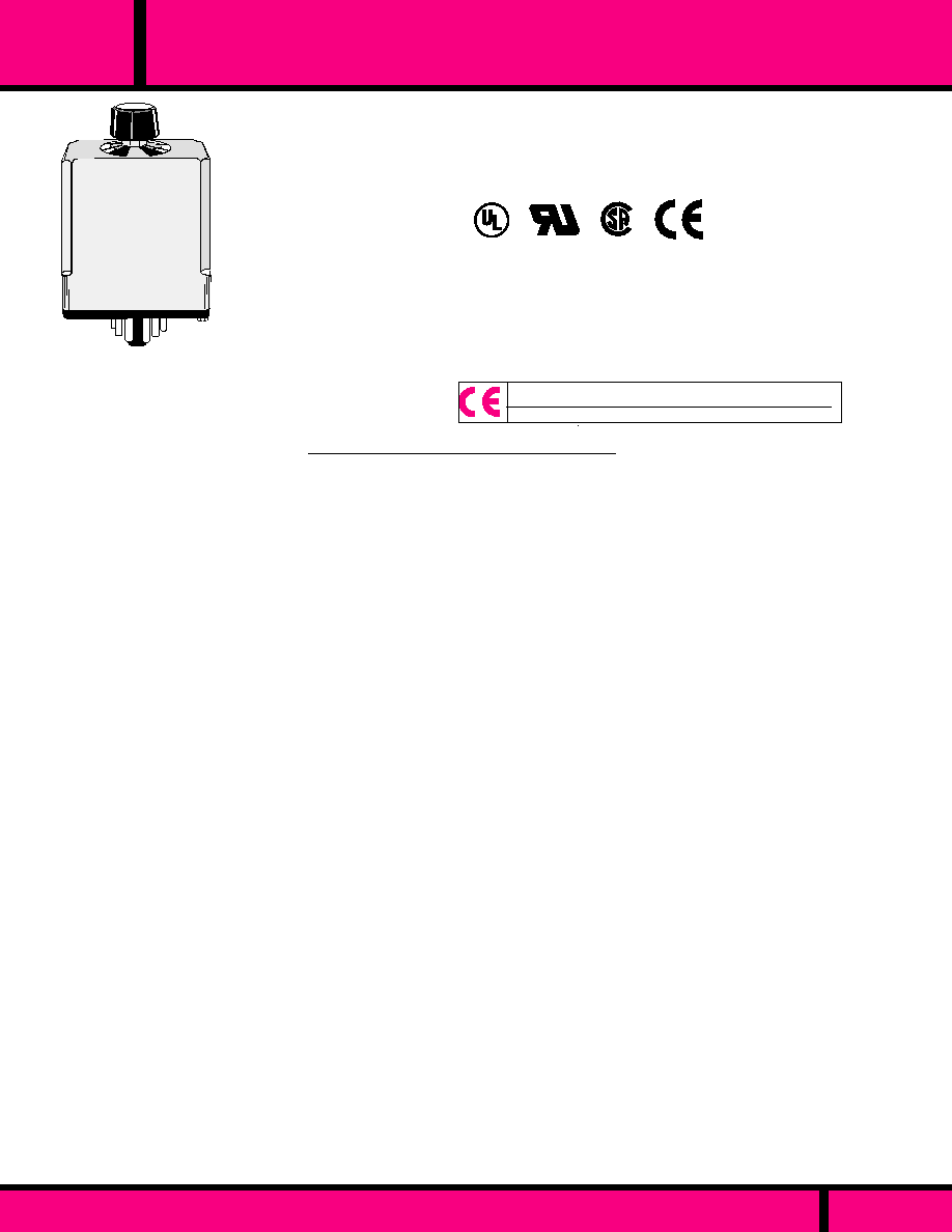
WEBSITE: www.magnecraft.com EMAIL:info@magnecraft.com FAX ON DEMAND 1-800/891-2957, DOCUMENT 100
PAGE 115
SPECIFICATIONS CLASS 211 TIME DELAY RELAYS
TIMING
Operating Modes Available:
Timing Adjustments Available:
Repeatability (repeat Accuracy
when Stabilized):
Timing change over temperature
and voltage range:
Timing Tolerance high end of range:
Timing Tolerance low end of range::
Reset time:
CONTACTS
Contact Configuration::
Contact Rating:
Contact Life:
Mechanical Life:
INPUT
Temperature Range (Operate):
Temperature Range (Storage):
Steady State Input Current:
PROTECTION
Reverse Polarity:
Transient:
Noise Immunity:
DIELECTRIC STRENGTH
Coil to Contacts:
Across Open Contacts:
MECHANICAL
Enclosure:
Mounting:
Operating Position:
Weight:
On Delay, Off Delay
0.1 to 1 Sec, thru 8 to 120 Minutes
�
0.1% max. or
�
33 mS AC min. or
�
10 mS DC. min.@ Constant voltage
& temperature
�
10%
- 0 to + 40%
+ 0 to - 40%
100 Milliseconds Max.
DPDT (2 Form C)
10 Amps @ 120VAC/30VDC Resistive
Load, 1/2 Hp @ 240 VAC, 1/3 Hp @120 VAC, NEMA B300
Pilot Duty.
200,000 Operations @ 120VAC, 10Amp resistive Load.
1,000,000 Operations @ 120 VAC,5 Amp Resistive Load
2,000,000 Operations @ 120VAC, 2 Amps Resistive Load.
50,000,000 Operations.
- 30 �C to + 55�C
- 55�C to + 85�C
20 mA @ 120 VAC, 40 mA @ 24 VDC,
20 mA @ 48 VDC 80 mA @ 24 VDC,
15 mA @ 230 VAC, 80 mA @ 12 VDC.
DC models only
UL 508 Surge test: 5000V for 50 uS
NEMA ICS2-230 2500 VAC
1500 V rms
1000 V rms
Polycarbonate dust cover.
Standard 8 or 11 Pin Octal
Any
4 oz. (115 grams)
OCTAL 8 & 11 PIN TIME DELAY RELAY
211
C L A S S
THE CLASS 211 TIME DELAY RELAY
MAKES USE OF HYBRID CIRCUITRY,
COMBINING INTEGRATED CIRCUITS
FOR A MULTITUDE OF TIMING
FUNCTIONS, AND THE RELIABILITY
OF RELAY TECHNOLOGY.
CLASS 211
�
0.1 % REPEATABILITY
DPDT, 10 AMP CONTACTS
FIELD ADJUSTABLE TIMING
*
RELEVANT IEC CONTACT UTILIZATION CATEGORIES
COMPLIES WITH
REQUIREMENTS OF
* IEC STANDARDS
947-4-1 AND 947-5-1
LOW VOLTAGE DIRECTIVE.
*1EC = INTERNATIONAL
ELECTROTECHNICAL COMMISSION
AC-1, AC-3, DC-1, AC-15
UL Recognized
File No: E43641
WHEN USED WITH
SOCKET
70-464-1 (8PIN)
70-465-1 (11 PIN)
(SEE SECTION 11 FOR RELEVANT UTILIZATION CATEGORIES.)
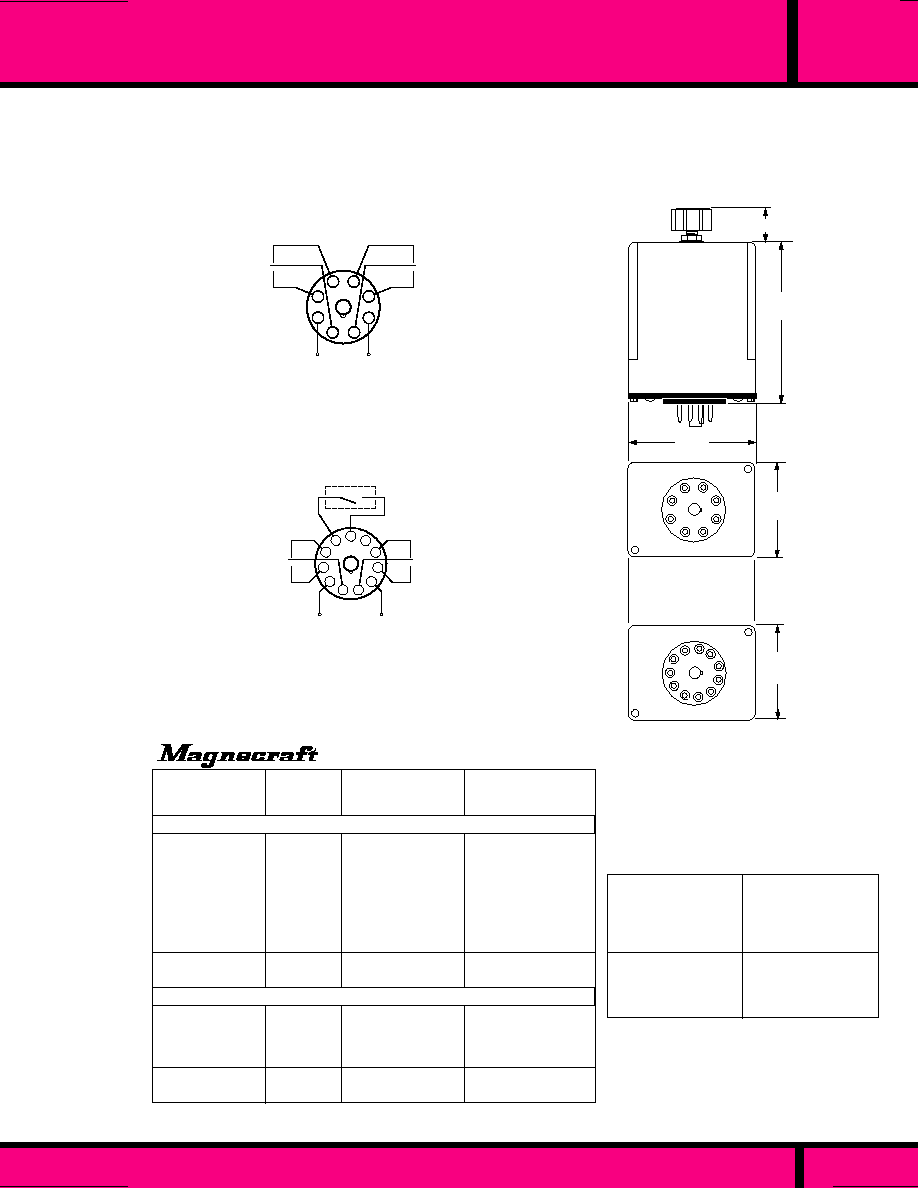
OCTAL 8 & 11 PIN TIME DELAY RELAY
C L A S S
211
PAGE 116
WEBSITE: www.magnecraft.com EMAIL:info@magnecraft.com FAX ON DEMAND 1-800/891-2957, DOCUMENT 100
120 VAC
120 VAC
120 VAC
120 VAC
120 VAC
120 VAC
120 VAC
120 VAC
24 VDC
24 VDC
120 VAC
120 VAC
120 VAC
120 VAC
24 VDC
24 VDC
0.1 to 1.0 Seconds
0.1 to 10 Seconds
1.0 to 180 Seconds
2.0 to 300 Seconds
1.0 to 15 Minutes
2.0 to 30 Minutes
4.0 to 60 Minutes
8.0 to 120 Minutes
0.1 to 10 Seconds
1.0 to 180 Seconds
0.1 to 10 Seconds
1.0 to 180 Seconds
2.0 to 300 Seconds
1.0 to 15 Minutes
0.1 to 10 Seconds
1.0 to 180 Seconds
W211ACPSOX-18
W211ACPSOX-5
W211ACPSOX-7
W211ACPSOX-8
W211ACPSOX-60
W211ACPSOX-61
W211ACPSOX-62
W211ACPSOX-63
W211CPSOX-1
W211CPSOX-3
W211ACPSRX-5
W211ACPSRX-7
W211ACPSRX-8
W211ACPSRX-60
W211CPSRX-1
W211CPSRX-3
PART
NUMBERS
NOMINAL
INPUT
VOLTAGE
TIMING
RANGE
OFF DELAY
PART NUMBERS SHOWN ALSO AVAILABLE THRU STOCKING DISTRIBUTION.
ON DELAY
CDB-38-70001
CDB-38-70003 *
CDB-38-70005 *
CGB-38-70005M
CGB-38-70010M
-
CGB-38-70050M
CB-1007B70
CDD-38-30003 *
CDD-38-30005 *
CHB-38-70011
CHB-38-70013
-
-
CHD-38-30011
CHD-38-30013
SEE SECTION 10
FOR
MATING SOCKETS
CGB-38-70010S
CHB-38-70001
CKB-38-70010
CB-1003B-70
W211ACPSOX-5
CKB-38-70180
CHB-38-70003
CB-1005B-70
W211ACPSOX-7
*
ADDITIONAL EQUIVALENTS TO P&B
W211CPSOX-3
CHD-38-30003
CB-1030D-30
W211CPSOX-1
CHD-38-30001
CB-1028D-30
2.93
(74.4)
1.75
(44.4)
1
2
7
8
4
3
5
6
2.37
(60.3)
.
562 (14.2)
8 PIN OCTAL
ON-DELAY
1.75
(44.4)
2
3
4
5
6
7
8
9
10
11
1
11 PIN OCTAL
OFF-DELAY
OUTLINE DIMENSIONS
Dimensions shown in Inches and (Millimeters)
2
v
w
4
1
3
5
6
7
8
v
w
INPUT
EXTERNAL TRIGGER
SWITCH
1
11
10
9
8
7
6
4
3
2
5
q
q
v
v
w
v
w
INPUT
EXTERNAL SWITCH SHALL NOT BE CONNECTED
TO ANY EXTERNAL LOAD OR VOLTAGE. DAMAGE
TO INTERNAL COMPONENTS CAN OCCUR.
WIRING DIAGRAMS
VIEWED FROM PIN END
CROSS REFERENCE
TO
POTTER & BRUMFIELD
ON DELAY
OFF DELAY

1
11
10
9
8
7
6
4
3
2
5
q
q
v
v
w
v
w
24VAC/VDC
INPUT
120VAC 50/60 Hz
+
-
2.93
(74.4)
.
562 (14.2)
1.75
(44.45)
2
1
3
4
5
6
7
8
9
10
11
11 PIN OCTAL PLUG-IN
WIRING DIAGRAMS
VIEWED FROM PIN END
OUTLINE DIMENSIONS
Shown in Inches and (Millimeters)
WEBSITE: www.magnecraft.com EMAIL:info@magnecraft.com FAX ON DEMAND 1-800/891-2957, DOCUMENT 100
CLASS 211 PROGRAMMABLE TIME DELAY RELAY
�
0.1 % REPEATABILITY
3 INPUT VOLTAGE RANGES
�
4 PROGRAMMABLE FUNCTIONS
�
62 PROGRAMMABLE TIMING RANGES
RATED AT 10 AMPS, DPDT CONTACTS
UL Recognized
File No: E43641
AC-1, AC-3, DC-1, AC-15
COMPLIES WITH
REQUIREMENTS OF
* IEC STANDARDS
947-4-1 AND 947-5-1
LOW VOLTAGE DIRECTIVE.
*1EC = INTERNATIONAL
ELECTROTECHNICAL COMMISSION
SEE SECTION 10
FOR
MATING SOCKETS
PAGE 117
2.37
(60.19)
SPECIFICATIONS CLASS 211PROG TDR
TIMING
Operating Modes Available:
Timing Adjustments Available:
Repeatability (repeat Accuracy
when Stabilized):
Timing change over tempera-
ture and voltage range:
Timing Tolerance:
Reset time:
CONTACTS
Contact Configuration:
Contact Rating:
Contact Life:
Mechanical Life:
INPUT
Temperature Range (Operate):
Temperature Range (Storage):
Steady State Input Current:
PROTECTION
Reverse Polarity:
Transient:
Noise Immunity:
DIELECTRIC STRENGTH
Coil to Contacts:
Across Open Contacts:
MECHANICAL
Enclosure:
Mounting:
Mounting Position:
Weight:
211PROGX
PROGRAMMABLE TIME DELAY RELAY
WHEN USED
WITH SOCKET
70-465-1
�
SELECTION OF TIMING RANGE AND TIMING
FUNCTIONS ARE OBTAINED BY SETTING
SWITCH POSITIONS IN A DIP SWITCH BANK
(SEE SECTION 11 FOR RELEVANT UTILIZATION CATEGORIES.)
On Delay, Off Delay, One Shot, On & Off Delay
0.1 to 1 Sec, thru 12 to 120 Minutes
�
0.1% max. or
�
33 mS AC min., or
�
10 mS DC.
�
10%
�
20 %
100 mS Relay On (200 mS max Relay Off)
DPDT (2 Form C)
10 Amps @ 120VAC/30VDC Resistive
Load, 1/2 Hp @ 240 VAC, 1/3 Hp @ 120 VAC,
NEMA B300 Pilot Duty.
200,000 Operations @ 120VAC, 10 Amp
resistive Load.
1,000,000 Operations @ 120VAC, 5 Amp
Resistive Load
2,000,000 Operations @ 120VAC, 2 Amps
Resistive Load.
100,000,000 Operations.
- 30 �C to + 55�C
- 40�C to + 85�C
45 mA Max..
Yes
UL 508 Surge test: 5000V for 50 uS
NEMA ICS2-230 2500VAC
1500 V rms
1000 V rms
Polycarbonate dust cover.
Standard 11 Pin Octal
Any
4 oz. (115 grams)
ON DELAY, OFF DELAY, ONE SHOT, ON & OFF DELAY
62 Programmable
Timing Ranges.
120 VAC, 50/60Hz
24VAC/VDC on Pin 7
W211PROGX-1
NOMINAL
INPUT
VOLTAGE
TIMING
RANGE
PART NUMBER
PART NUMBERS SHOWN ALSO AVAILABLE THRU STOCKING DISTRIBUTION.
**
EXTERNAL CONTROL SWITCH REQUIRED FOR OFF DELAY, ONE SHOT AND
ON & OFF DELAY FUNCTIONS.
EXTERNAL SWITCH SHALL NOT BE CONNECTED TO ANY EXTERNAL LOAD OR
VOLTAGE. DAMAGE TO INTERNAL COMPONENTS CAN OCCUR.
**
EXTERNAL CONTROL
SWITCH
*
RELEVANT IEC CONTACT UTILIZATION CATEGORIES
THE CLASS 211 TIME DELAY RELAY
MAKES USE OF HYBRID CIRCUITRY,
COMBINING INTEGRATED CIRCUITS
FOR A MULTITUDE OF TIMING
FUNCTIONS, AND THE RELIABILITY
OF RELAY TECHNOLOGY.
To function as a On-Delay timer, a jumper wire must be
connected in place of the external control switch.
C L A S S

C L A S S
67
MINIATURE 5 AMP TIME DELAY RELAY
TIMING
Operating Modes Available:
Timing Adjustments Available:
Repeatability (repeat Accuracy
when Stabilized):
Reset time:
CONTACTS
Contact Configuration:
Contact Rating:
Contact Life:
Mechanical Life:
INPUT
Nominal Input Voltage:
Temperature Range (Operate):
Temperature Range (Storage):
Steady State Input Current:
PROTECTION
Reverse Polarity:
Transient:
DIELECTRIC STRENGTH
Coil to Contacts:
Across Open Contacts:
MECHANICAL
Enclosure:
Mounting:
Weight:
Special Note:
On Delay,
0.1 to 240 Seconds
�
2% max. @ Nominal Voltage, 25�C
100 Milliseconds Max
DPDT ( 2 Form "C").
5 Amps @ 120VAC/28 VDC Resistive
50,000 Operations @ 120 VAC 5 Amps
Resistive
1,500,000 Operations @ 120VAC, 2 Amps
resistive Load.
12,000,000 Operations @ 120 VAC 1Amp
Resistive Load
50,000,000 Operations
12 VDC, 24 VDC
-30�C to + 55�C
-50�C to +85�C
40 mA @ 24 VDC, 80 mA @ 12 VDC
DC models only
Twice Nominal Voltage for 1 Millisecond
500 V rms
1250 V rms
Polycarbonate dust cover.
Socket Plug-in/Solder. Also Available with
P.C. Terminals.
1.2 oz. 35.2 Grams
Use 6 Pole Socket with plug-in style
relays. .
SPECIFICATIONS CLASS 67 TIME DELAY RELAYS
.170
(4.3)
Elongated Hole .100 x .040 ( 2 x .1)
1.18 Max.
(30.2)
3-48UNC-2A Thd.
.094
(2.3)
1.37
(34.9)
.734
(18.6)
All Contact Terminals are .010 Thick
all coil terminals are .018 Thick.
.400
(10.1)
.458
(11.6)
1
4
5
6
15
14
16
7
+
-
WIRING DIAGRAM
.56
(14.2)
CHASSIS CUTOUT
for panel mounting.
.280
(7.11)
.140
(3.5)
.352
(8.9)
.109 DIA. (2.77)
.656
(16.7)
.790
(19.8)
VIEWED FROM PIN END
OUTLINE DIMENSIONS
Dimensions shown are in Inches and ( Millimeters).
NOMINAL
INPUT
VOLTAGE
W67CPSOX-1
W67CPSOX-2
12 VDC
24 VDC
0.1 to 30 Seconds
0.1 to 30 Seconds
TIMING
RANGE
R12-3012X2E1
R12-3024X2E1
CROSS REFERENCE
TO
POTTER & BRUMFIELD
"ON" DELAY
PART NUMBERS SHOWN ALSO AVAILABLE THRU STOCKING DISTRIBUTION
PART
NUMBERS
CLASS 67 TIME DELAY RELAY
�
2% REPEATABILITY
DC OPERATION
PLUG-IN/SOLDER TERMINALS
UL Recognized
File No: E43641
.200 Max.
(5.1)
WEBSITE: www.magnecraft.com EMAIL:info@magnecraft.com FAX ON DEMAND 1-800/891-2957, DOCUMENT 100
PAGE 118
OTHER COIL VOLTAGES, TIMING RANGES, P.C. TERMINALS AND
4PDT CONTACT COMBINATION AVAILABLE ON SPECIAL ORDER.
120 VAC INPUT DESIGN AVAILABLE, CONTACT FACTORY.
SEE SECTION 10
FOR
MATING SOCKETS

SEE SECTION 10
FOR
MATING SOCKETS
CLASS 222
�
0.1 % REPEATABILITY
DPDT, 10 AMP CONTACTS
FIELD ADJUSTABLE ON
AND OFF TIME.
OCTAL 8 PIN REPEAT CYCLE TIMER
C L A S S
*
RELEVANT IEC CONTACT UTILIZATION CATEGORIES
AC-1, AC-3, DC-1, AC-15
UL Recognized
File No. E43641
2.93
(74.4)
1.75
(44.4)
1
2
7
8
4
3
5
6
2.37
(60.3)
.
562 (14.2)
8 PIN OCTAL
ON-DELAY
2
v
w
4
1
3
5
6
7
8
v
w
INPUT
WIRING DIAGRAMS
VIEWED FROM PIN END
Repeat cycle timing only.
0.1 to 1 Sec, to 24 hours
�
0.1% max. or
�
33 mS AC min. or
�
10 mS DC min. at constant voltage &
temperature..
�
10%
- 0 to + 40%
+ 0 to - 40%
100 Milliseconds Max.
DPDT (2 Form C)
10 Amps @ 120VAC/30VDC Resistive
Load, 1/2 Hp @ 240 VAC, 1/3 Hp @ 120 VAC,
NEMA B300 Pilot Duty.
200,000 Operations @ 120VAC, 10Amp
resistive Load.
1,000,000 Operations @ 120 VAC 5 Amp
Resistive Load
2,000,000 Operations @ 120VAC 2 Amps
Resistive Load.
50,000,000 Operations.
- 30 �C to + 55�C
- 55�C to + 85�C
25 mA @ 120 VAC, 45 mA @ 24 VDC,
24 mA @ 48 VDC 85 mA @ 24 VDC,
25 mA @ 230 VAC.
DC models only
UL 508 Surge test: 5000V for 50 uS
NEMA ICS2-230 2500VAC
1500 V rms
1000 V rms
Polycarbonate dust cover.
Standard 8 Pin Octal
Any
5 oz. (132 grams)
TIMING
Operating Modes Available:
Timing Adjustments Available:
Repeatability (repeat Accuracy
when Stabilized):
Timing change over tempera-
ture and voltage range:
Timing Tolerance high end of
range:
Timing Tolerance low end of
range::
Reset time:
CONTACTS
Contact Configuration:
Contact Rating:
Contact Life:
Mechanical Life:
INPUT
Temperature Range (Operate):
Temperature Range (Storage):
Steady State Input Current:
PROTECTION
Reverse Polarity:
Transient:
Noise Immunity:
DIELECTRIC STRENGTH
Coil to Contacts:
Across Open Contacts:
MECHANICAL
Enclosure:
Mounting:
Mounting Position:
Weight:
SPECIFICATIONS CLASS 222 REPEAT CYCLE TIMER
NOMINAL
INPUT
VOLTAGE
W222ACPFX-11
W222ACPFX-16
W222ACPFX-27
120 VAC
120 VAC
120 VAC
0.1 to 10 Seconds
3 to 300 Seconds
2 to 30 Minutes
0.1 to 10 Seconds
3 to 300 Seconds
2 to 30 Minutes
TIMING RANGE
"OFF" (T2) TIMING
TIMING RANGE
"ON" (T1) TIMING
PART NUMBERS
REPEAT CYCLE
CROSS REFERENCE
TO
POTTER & BRUMFIELD
CRB-48-70010
-
-
PART NUMBERS SHOWN ALSO AVAILABLE THRU STOCKING DISTRIBUTION.
OTHER VOLTAGES AND TIMING RANGES AND AVAILABLE THRU SPECIAL ORDER. CONTACT FACTORY.
THE CLASS 222 REPEAT CYCLE TIME
DELAY RELAY CAN BE ADJUSTED TO
ACHIEVE INDEPENDENT TIME
SETTINGS FOR BOTH "ON" AND
"OFF" TIMING RANGES.
COMPLIES WITH
REQUIREMENTS OF
* IEC STANDARDS
947-4-1 AND 947-5-1
LOW VOLTAGE DIRECTIVE.
*1EC = INTERNATIONAL
ELECTROTECHNICAL COMMISSION
WEBSITE: www.magnecraft.com EMAIL:info@magnecraft.com FAX ON DEMAND 1-800/891-2957, DOCUMENT 100
(SEE SECTION 11 FOR RELEVANT UTILIZATION CATEGORIES.)
PAGE 119
222

C L A S S
12 AMP ADJUSTABLE TIME DELAY RELAY
PLUG-IN STYLE
FLANGE MOUNT STYLE
CLASS 388
SHORT BODY
EXTERNAL
RESISTANCE
ADJUSTABLE
�
3 % REPEATABILITY
DPDT, 12 AMP CONTACTS
FIELD ADJUSTABLE TIMING
"ON" or "OFF" DELAY FUNCTIONS
AC-1, AC-3, DC-1, AC-15
COMPLIES WITH
REQUIREMENTS OF
* IEC STANDARDS
947-4-1 AND 947-5-1
LOW VOLTAGE DIRECTIVE.
*1EC = INTERNATIONAL
ELECTROTECHNICAL COMMISSION
*
RELEVANT IEC CONTACT UTILIZATION CATEGORIES
UL Recognized
File No: E43641
On Delay, Off Delay
.1 to 1 Seconds to 24 Hours
�
0.1% max. or
�
33 mS AC min. or
�
10 mS DC.@ Constant Voltage & Temperature.
�
10%
- 0 to + 40%
+ 0 to - 40%
DPDT (2 Form C)
12 Amps @ 120 VAC/28 VDC Resistive
1/3 HP, 120 VAC, 1/2 HP, 240 VAC
B300 Pilot Duty.
100,000 Operations @ 120 VAC 12 Amps Resistive Load.
1,000,000 Operations @ 28 VDC 5 Amps Resistive Load.
5,000,000 Operations
- 30 �C to + 55�C
- 55�C to + 85�C
20 mA @ 120 VAC, 60 mA @ 24 VDC,
DC models only
Twice nominal voltage for 1 millisecond
1500 V rms
1000 V rms
Polycarbonate dust cover.
Any
3 oz. 96 grams
TIMING
Operating Modes Available:
Timing Adjustments Available:
Repeatability:
Percent Timing change over temperature
and voltage Range:
Timing Tolerance high end
Timing Tolerance low end:
CONTACTS
Contact Configuration:
Contact Rating:
Contact Life:
Mechanical Life:
INPUT
Temperature Range (Operate):
Temperature Range (Storage):
Steady State Input Current:
PROTECTION
Reverse Polarity:
Transient:
DIELECTRIC STRENGTH
Coil to Contacts:
Across Open Contacts:
MECHANICAL
Enclosure:
Operating Position:
Weight:
SPECIFICATIONS CLASS 388 TIME DELAY RELAYS
PAGE 120
WEBSITE: www.magnecraft.com EMAIL:info@magnecraft.com FAX ON DEMAND 1-800/891-2957, DOCUMENT 100
(SEE SECTION 11 FOR RELEVANT UTILIZATION CATEGORIES.)
388
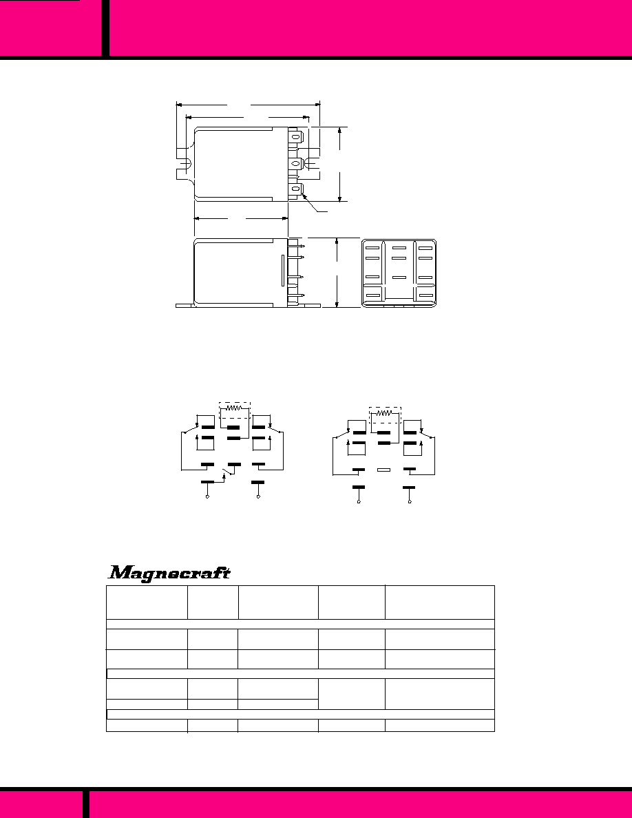
12 AMP ADJUSTABLE TIME DELAY RELAY
C L A S S
388
W388ACPSOX-1
W388ACPSOX-2
W388CPSOX- 1
W388CPSOX-2
0.1 to 10 Seconds
1.0 to 120 Seconds
0.1 to 10 Seconds
1.0 to 120 Seconds
0.1 to 10 Seconds
1.0 to 120 Seconds
1.0 to 120 Seconds
1.0 to 120 Seconds
W388ACQSOX-1
W388ACQSOX-2
W388CQSOX-2
W388CPSRX-22
TIMING
RANGE
NOMINAL
INPUT
VOLTAGE
PART NUMBER
ON DELAY PLUG-IN STYLE
ON DELAY SURFACE MOUNT FLANGE STYLE
OFF DELAY PLUG-IN STYLE
120 VAC
120 VAC
24 VDC
24 VDC
120 VAC
120 VAC
24 VDC
24 VDC
CROSS REFERENCE
TO
POTTER & BRUMFIELD
EXTERNAL
RESISTOR
20K OHMS
PER SECOND
16 K OHMS
PER SECOND
20 K OHMS
PER SECOND
16K
per Second
PART NUMBERS SHOWN ALSO AVAILABLE THRU STOCKING DISTRIBUTION.
CUF-42-70010
CUF-42-70120
CUH-42-30120
-
CUF-41-70010
CUF-41-70120
CUH-41-30010
CUH-41-30120
4
5
7
8
1
2
6
9
3
B
A
+
-
EXTERNAL
SWITCH
OFF DELAY
INPUT
EXTERNAL
RESISTOR
WIRING DIAGRAMS FOR FIXED STYLE TIME DELAY RELAYS
Voltage must be applied to terminals "A" & "B" continuously.
THE EXTERNAL TRIGGER SWITCH SHOULD NOT BE CONNECTED
TO ANY EXTERNAL LOAD OR VOLTAGE SOURCE. DAMAGE TO
INTERNAL COMPONENTS CAN OCCUR.
4
7
8
1
6
9
3
B
A
+
-
ON DELAY
INPUT
5
2
EXTERNAL
RESISTOR
4
1
2
5
A
B
8
9
7
3
6
1.53 Max.
(38.8)
1.40 Max.
(35.7)
1.90 Max.
(48.4)
.187 (4.74)
Q.C. Terminals
OUTLINE DIMENSIONS
Dimensions Shown in "Inches " & (Millimeters).
2.90 Max.
(73.8)
2.50
(63.5)
THE PLUG-IN STYLE TIMER HAS THE SAME CASE DIMENSIONS
AS THE FLANGE MOUNT STYLE EXCEPT IT HAS NO FLANGE
AND IT IS ALSO SOCKET MOUNTABLE.
PAGE 121
WEBSITE: www.magnecraft.com EMAIL:info@magnecraft.com FAX ON DEMAND 1-800/891-2957, DOCUMENT 100
SEE SECTION 10
FOR MATING SOCKETS

C L A S S
388
12 AMP ADJUSTABLE TIME DELAY RELAY
CLASS 388 ADJUSTABLE
CHOICE OF LONG or MEDIUM BODY
�
0.1 % REPEATABILITY
DPDT, 12 AMP CONTACTS
FIELD ADJUSTABLE TIMING
"ON" or "OFF" DELAY FUNCTIONS
AC-1, AC-3, DC-1, AC-15
COMPLIES WITH
REQUIREMENTS OF
* IEC STANDARDS
947-4-1 AND 947-5-1
LOW VOLTAGE DIRECTIVE.
*1EC = INTERNATIONAL
ELECTROTECHNICAL ICOMMISSION
UL Recognized
File No: E43641
*
RELEVANT IEC CONTACT UTILIZATION CATEGORIES
TIMING
Operating Modes Available:
Timing Adjustments Available:
Repeatability:
Timing change over temperature
and voltage Range:
Timing Tolerance high end:
Timing Tolerance low end:
Reset Time:
CONTACTS
Contact Configuration:
Contact Rating:
Contact Life:
Mechanical Life:
INPUT
Temperature Range (Operate):
Temperature Range (Storage):
Steady State Input Current:
PROTECTION
Reverse Polarity:
Transient:
Noise Immunity:
DIELECTRIC STRENGTH
Coil to Contacts:
Across Open Contacts:
MECHANICAL
Enclosure:
Terminals:
Mounting Position:
Weight:
On Delay, Off Delay
.1 to 1 Seconds to 8 to 120 Minutes
�
0.1%
�
33 mS AC min. or
�
10 mS DC.
@ Constant Voltage & Temperature.
�
10%
- 0 to + 40%
+ 0 to - 40%
100 mS Max.
DPDT (2 Form C)
12 Amps @ 120 VAC/28 VDC Resistive
1/3 HP, 120 VAC, 1/2 HP, 240 VAC
NEMA B300 Pilot Duty.
100,000 Operations @ 120 VAC 12 Amps Resistive Load.
1,000,000 Operations @ 120 VAC 5 Amps Resistive Load
2,000,000 Operations @ 120 VAC 2 Amps Resistive Load.
5,000,000 Operations
- 30 �C to + 55�C
- 55 �C to + 85�C
20 mA @ 120 VAC, 60 mA @ 24 VDC, 20mA @ 48 VDC,
80 mA @ 24 VAC, 15 mA @ 230 VAC, 120mA @ 12 VDC
DC models only
UL 508 Surge test: 5000V for 50 uS (Long Body Only).
Twice Nominal for 1 Millisecond (Medium Body Only).
NEMA ICS2-230: 2500 VAC (Long Body Only).
2000 V rms
1000 V rms
Polycarbonate dust cover.
3/16" Q.C. Terminals. P.C. Available.
Any
Aprox. 4 oz., 96 grams
SPECIFICATIONS CLASS 388 TIME DELAY RELAYS
WEBSITE: www.magnecraft.com EMAIL:info@magnecraft.com FAX ON DEMAND 1-800/891-2957, DOCUMENT 100
PAGE 122
(SEE SECTION 11 FOR RELEVANT UTILIZATION CATEGORIES.)

C L A S S
388
12 AMP ADJUSTABLE TIME DELAY RELAY
.312
(7.9)
.625
(15.8)
2.40 Max. (Medium Body)
(61.1)
2.90 Max. (Long Body)
(73.8)
1
2
3
4
5
6
7
8
A
B
9
1.53
(38.8)
1.40
(35.7)
ON DELAY LONG & MEDIUM BODY
4
5
7
8
1
2
6
9
3
B
A
+
-
EXTERNAL
TRIGGER SWITCH
4
5
7
8
1
2
6
9
3
B
A
+
-
INPUT
INPUT
OFF DELAY LONG BODY
4
5
7
1
2
6
9
3
B
A
+
-
INPUT
8
EXTERNAL
TRIGGER
SWITCH
OFF DELAY MEDIUM BODY
120 VAC
120 VAC
0.1 to 10 Seconds
1.0 to 180 Seconds
ON DELAY - LONG BODY
24 VDC
24VDC
120 VAC
120 VAC
24 VDC
24 VDC
W388ACPSOX-42
W388ACPSOX-44
-
-
OFF DELAY - MEDIUM BODY
ON DELAY - MEDIUM BODY
-
-
-
CLB-51-70120 *
-
-
W388CPSRX-2
W388CPSRX-4
W388ACPSRX-101
W388ACPSOX-101
W388CPSRX-23
W388CPSOX-101
0.1 to 10 Seconds
1.0 to 180 Seconds
1.0 to 120 Seconds
1.0 to 120 Seconds
1.0 to 120 Seconds
1.0 to 120 Seconds
* THE CASE LENGTH ON THE MAGNECRAFT MEDIUM BODY IS 2.40 LONG VS P&B, 2.156 LONG.
OFF DELAY - LONG BODY
ON DELAY - MEDIUM BODY
OFF DELAY - MEDIUM BODY
PART NUMBERS SHOWN ALSO AVAILABLE THRU STOCKING DISTRIBUTION.
CROSS REFERENCE
TO
POTTER & BRUMFIELD
TIMING
RANGE
NOMINAL
INPUT
VOLTAGE
PART
NUMBERS
THE EXTERNAL TRIGGER SWITCH SHOULD NOT BE CONNECTED TO ANY EXTERNAL LOAD OR VOLTAGE
SOURCE. DAMAGE TO INTERNAL COMPONENTS CAN OCCUR.
WIRING DIAGRAMS FOR ADJUSTABLE STYLE TIME DELAY RELAYS
Voltage must be applied to terminals "A" & "B" continuously.
OUTLINE DIMENSIONS
Dimensions are Shown In Inches and (Millimeters).
PAGE 123
WEBSITE: www.magnecraft.com EMAIL:info@magnecraft.com FAX ON DEMAND 1-800/891-2957, DOCUMENT 100
SEE SECTION 10
FOR MATING SOCKETS

C L A S S
388
AC-1, AC-3, DC-1, AC-15
*
RELEVANT IEC CONTACT UTILIZATION CATEGORIES
CLASS 388
TRUE OFF DELAY
DOES NOT REQUIRE CONTROL
POWER DURING TIMING CYCLE
�
3% REPEAT TIMING ACCURACY
FIELD ADJUSTABLE
COMPLIES WITH
REQUIREMENTS OF
* IEC STANDARDS
947-4-1 AND 947-5-1
LOW VOLTAGE DIRECTIVE.
*1EC = INTERNATIONAL
ELECTROTECHNICAL COMMISSION
UL Recognized
File No: E43641
SPECIFICATIONS CLASS 388 TRUE OFF DELAY
True Off Delay
0.1 to 10 Seconds thru 0.5 to 5 Minutes
�
3% @ Nominal Voltage & 25�C
100 mS Max.
- 10�C to + 55�C
- 40�C to + 85�C
10 mA @ 120VAC, 15 mA @ 24VDC fixed
DPDT (2 Form C)
12 Amps @ 120 VAC/28 VDC Resistive
1/3 HP, 120 VAC, 1/2 HP, 240 VAC
NEMA B300 Pilot Duty.
100,000 Operations @ 120 VAC 12 Amps Resistive
Load.
1,000,000 Operations @ 120 VAC 5 Amps Resistive
Load
2,000,000 Operations @ 120 VAC 2 Amps Resistive
Load.
2000 V rms
1000 V rms
2000 VAC for 50 Microseconds
(DC Models Only)
Polycarbonate dust cover
Square Base Plug-in
3/16" X .020" Quick Connect, P.C. Terminals Available
4 oz. 96 grams
The Class 388 Adjustable True Off Delay
Relay combines a Solid State Timing circuit
with a state of the art Magnetic Latching
relay. This combination allows the relay
to Pull-in when power is applied to the input.
Timing starts when power is removed from
the input and at the end of the preset timing
period the relay will dropout.
4
5
7
8
1
2
6
9
3
B
A
+
-
INPUT
WIRING DIAGRAM
Viewed from Pin End
1
2
3
4
5
6
7
8
A
B
9
1.40
(35.7)
.312
(7.9)
.625
(15.8)
2.90 Max.
(73.8)
1.53
(38.8)
OUTLINE DIMENSIONS
Dimensions are Shown In Inches and Millimeter
NOMINAL
INPUT
VOLTAGE
120 VAC
120 VAC
24 VDC
24 VDC
0.6 to 60 Seconds
0.1 to 10 Seconds
0.1 to 10 Seconds
0.6 to 60 Seconds
AC OPERATED
DC OPERATED
TIMING
RANGE
W388ACPSRX-29
W388ACPSRX-30
W388CPSRX-35
W388CPSRX-36
PART
NUMBERS
PART NUMBERS SHOWN ALSO AVAILABLE THRU STOCKING DISTRIBUTION.
SEE SECTION
10
FOR MATING SOCKETS
PAGE 124
WEBSITE: www.magnecraft.com EMAIL:info@magnecraft.com FAX ON DEMAND 1-800/891-2957, DOCUMENT 100
ADJUSTABLE TRUE OFF DELAY RELAY
Observe polarity on DC models
TIMING
Operating Modes Available:
Timing Adjustments Available:
Repeatability:
Reset time:
INPUT
Temperature Range Operate:
Temperature Range Storage:
Input Current:
CONTACTS
Contact Configuration:
Contact Rating:
Contact Life:
DIELECTRIC STRENGTH
Coil to Contacts:
Across Open Contacts:
Transient:
Reverse Polarity Protection:
MECHANICAL
Enclosure:
Mounting:
Terminals:
Weight:
(SEE SECTION 11 FOR RELEVANT UTILIZATION CATEGORIES.)
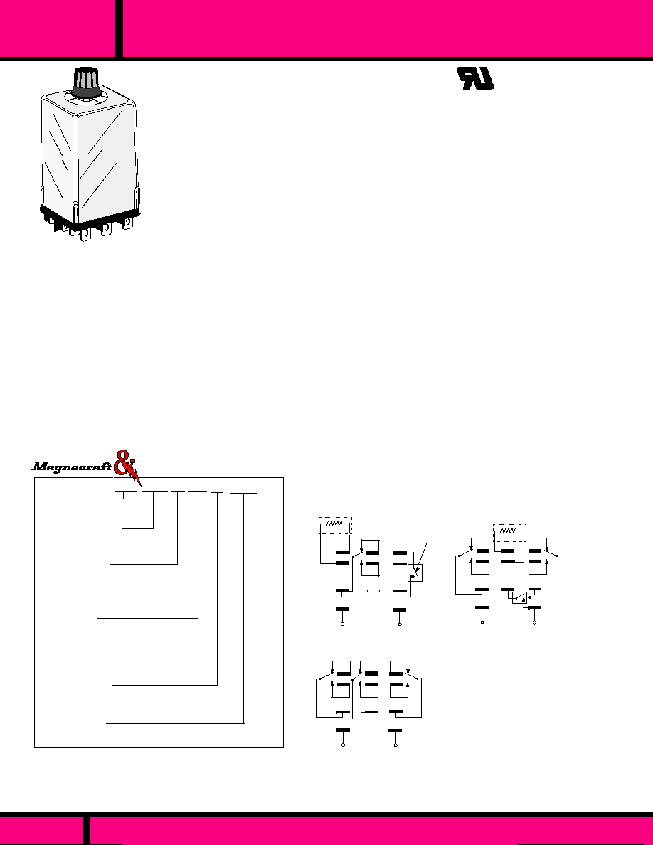
UL Recognized
File No. E13224
SERIES 286 ON DELAY, 287 OFF DELAY
AC OR DC INPUT
1, 2 OR 3 POLE 10 AMP CONTACTS.
286/287
SERIES
10 AMP SQUARE BASE TIME DELAY RELAY
GENERAL SPECIFICATIONS SERIES 306 TIMER
AC: 24 to 240, DC: 12 to 125
AC - 85% of Nominal
DC - 80% of Nominal
110% of nominal voltage
Silver Cadmium Oxide.
10 Amps @ 120/240 VAC
10 Amps @ 28 VDC
1/3 Hp@ 120AC
1/2 Hp @ 240 VAC
�
3% @ 20�C to 25�C (AC +16 mS)
Adjustable
�
10% Within temperature
& voltage range. Fixed:
�
10% @ 25�C
100 mS up to 60 Seconds\
150 mS, 60 to 300 Seconds
500 V rms across open contacts
1500 V rms between current carrying
parts
1000 Megohms min. @ 500 VDC.
5 mS, 0 to 2000 V 20 uSec peak
No false contacting is power is
interupted during timing.
DC coil are polarity protected.
-
10�C to +70 �C
10 Million Operations no load
100,000 Operations @ Rated Load.
Clear Polycarbonate
5.0 oz approx. (142 g)
INPUT
Coil Voltage
Nominal Voltage:
Minimum Oper. Voltage:
Max. allowed voltage:
CONTACTS
Contact Material:
Rating:
OPERATIONAL CHARACTERISTICS
Repeatability:
Accuracy:
Recycle Time:
INSULATION CHARACTERISTICS
Dielectric Strength:
All Mutually Insulated Points:
Insulation Resistance:
Transient Protection:
False Contacting:
Inverse polarity protection:
ENVIRONMENTAL CAPABILITIES
Ambient Temperature Rating:
LIFE EXPECTANCY
Mechanical:
Electrical:
MISCELLANEOUS
Enclosure:
Weight:
The series 286 On Delay & 287 Off Delay
Time Delay Relays have timing ranges
from 0.1 to 300 Seconds. The 286 timer has
up to three poles and the 287 timer has up to
two poles. The 286 & 287 time delay relays
are rated at 10 Amps, 120/240 Vac, 28 Vdc.
SEE SECTION 10
FOR
MATING SOCKETS
EXTERNAL
SWITCH
287 MODEL
ONLY
Notes:
Note 1: Bracket & top stud Not available with
adjustable timing.
4
7
1
6
9
3
B
A
5
2
EXTERNAL
RESISTOR
+
-
8
286XBX (DPDT)
287XBX (DPDT)
INPUT
5
8
2
4
7
1
A
6
9
3
B
EXTERNAL
RESISTOR
+
-
INPUT
286XAX (SPDT)
287XAX (SPDT)
7
1
6
9
3
B
A
INPUT
+
-
ON DELAY
286XCX
8
5
2
4
WIRING DIAGRAM
Viewed from Terminal Side
EXTERNAL
SWITCH
287 MODEL
ONLY
286 XAX C 001 F 120A
Typical Part Number
(F * Models) - timing code does not apply. Specify single delay time requirement
(R ** Models)- Available only for SPDT and DPDT models. External potentiometer
required.
Example of typical fixed time delay relay part number- 286XBXCS1-3.5F-120A
(ON DELAY, DPDT, TOP STUD, 3.5 SEC FIXED, 120 VAC COIL INPUT)
Series
286 - ON DELAY
287 - OFF DELAY
Contact Arrangements
XAX (SPDT)
XBX (DPDT)
XCX (3PDT)
Mounting Options
C
Plug-in
C1
Note 1
Bracket
CS1
Note 1
Top Stud
C2
Side Tapped Hole
CS2
Side Stud
Timing Ranges
0.1 - 1.0 Sec - Code 001
0.2 - 2.0 Sec - Code 002
1.0 - 10 Sec - Code 010
3.0 - 30 Sec - Code 030
6.0 - 60 Sec - Code 060
18 - 180 Sec - Code 180
30 - 300 Sec - Code 300
Adjustment Options
Adjustment Knob) - No Code
Fixed Delay - Specify Fixed Time & Code F *
Remote Adjustment - Code R **
Operating Voltage
AC; 24, 48, 120, 240 (Add "A" )
DC; 12, 24, 48, 115-125 (Add "D")
PAGE 125
WEBSITE: www.magnecraft.com EMAIL:info@magnecraft.com FAX ON DEMAND 1-800/891-2957, DOCUMENT 100
SEE SECTION
10
FOR MATING SOCKETS
Struthers-Dunn
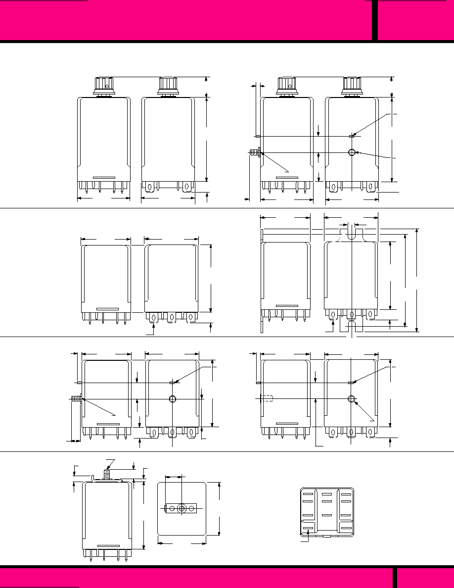
286/287
SERIES
10 AMP SQUARE BASE TIME DELAY RELAY
PAGE 126
WEBSITE: www.magnecraft.com EMAIL:info@magnecraft.com FAX ON DEMAND 1-800/891-2957, DOCUMENT 100
6-32 tapped hole
or 6-32 stud
Anti-rotation Tab
Fits 0.177 dia. hole
(No. 16 Drill)
OUTLINE DIMENSIONS
Dimensions shown are in INCHES and (millimeters)
.625
(15.87)
.281 typ.
(7.14)
1.50 Max.
(38.1)
1.375 Max.
(34.9)
2.90 Max.
(73.66)
PLUG-IN, ADJUSTABLE TIMING
4
1
2
5
A
B
8
9
7
3
6
1.875 Max.
(47.62)
1.375 Max.
(34.9)
.375
(9.52)
.281
(7.14)
.125 Max.
(3.17)
6-32 STUD
ALL TERMINALS .187 X .020
(4.74 X .508)
.437
(11.11)
1.50 Max.
(38.1)
TOP STUD FIXED OR REMOTE TIMING
1.50 Max.
(38.1)
1.375Max.
(34.9)
12
12
.296
(7.54)
.125 Max.
(3.17)
1.125 Max.
(28.57)
.437
(11.1)
1.875 Max.
(47.62)
.281 typ.
(7.14)
6-32 Stud
1.50 Max.
(38.1)
1.375Max.
(34.9)
1.875 Max.
(47.62)
.281 typ.
(7.14)
SIDE STUD, FIXED OR REMOTE TIMING
12
12
1.50 Max.
(38.1)
.281 typ.
(7.14)
.625
(15.87)
.296
(7.54)
.125
(3.17)
.437
(11.1)
1.125 Max.
(28.57)
6-32 Stud
1.375Max.
(34.9)
SIDE STUD OR TAPPED HOLE, ADJUSTABLE TIMING
1.50 Max.
(38.1)
2.90 Max.
(73.66)
2.50
(63.5)
1.90 Max.
(48.26)
.160
(4.06)
TERMINALS .187 X .020
(4.74 X .508)
.281 typ.
(7.14)
1.375Max.
(34.9)
.125 Max.
(3.17)
1.875 Max.
(47.62)
1.375Max.
(34.9)
1.50 Max.
(38.1)
.437
(11.1)
.281 typ.
(7.14)
6-32 Tapped hole
1.125 Max.
(28.57)
SIDE TAPPED HOLE, FIXED OR REMOTE TIMING
BRACKET FIXED OR REMOTE TIMING
2.90 Max.
(73.66)
CODE C2, CS2
CODE C
CODE C
CODE CS1
CODE C1
CODE CS2
CODE C2
PLUG-IN FIXED OR REMOTE TIMING
TERMINALS .187 X .020
(4.74 X .508)
Anti-rotation Tab
Fits 0.177 dia. hole
(No. 16 Drill)
Anti-rotation Tab
Fits 0.177 dia. hole
(No. 16 Drill)
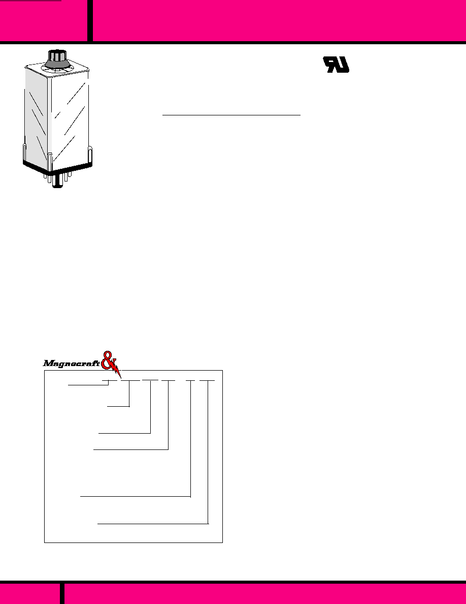
SERIES
326/327
OCTAL 8 & 11 PIN TIME DELAY RELAY
PAGE 127
WEBSITE: www.magnecraft.com EMAIL:info@magnecraft.com FAX ON DEMAND 1-800/891-2957, DOCUMENT 100
UL Recognized
File No. E13224
GENERAL SPECIFICATIONS SERIES 306 TIMER
AC: 24 to 240, DC: 12 to 125
AC - 85% of Nominal
DC - 80% of Nominal
110% of nominal voltage
Silver Cadmium Oxide.
10 Amps @ 120/240 VAC
10 Amps @ 30 VDC
1/3 Hp@ 120AC
1/2 Hp @ 240 VAC
DC:
�
3% @ 20�C. AC:
�
3% +16 mS @
20�C.
Adjustable
�
10% Within temperature
& voltage range.
20 mS
100 mS (for timing cycle up to 60 sec.)
150 mS (for timing cycle 60 to 300 sec)
500 V rms across open contacts
1500 V rms between mutually insulated
conductive elements.
1000 Megohms min. @ 500 VDC.
5 mS, 0 to 2000 V 20 uSec peak
-10�C to +70 �C
10 Million Operations no load
100,000 Operations @ Rated Load.
Clear Polycarbonate
5.0 oz approx. (142 g)
(F * Models) - timing code does not apply. Specify single delay time requirement
(R ** Models)- Available only for SPDT and DPDT models. External fixed or
adjustable resistor required.
Example of typical fixed time delay relay part number- 326XBX48P3.5F-120A
(ON DELAY, DPDT, OCTAL PLUG, 3.5 SEC FIXED, 120 VAC POWER INPUT)
Typical Part Number
326 XAX 48P 001 F 120A
Series
326 - 0N DELAY
327 - OFF DELAY
Contact Arrangements
XAX (SPDT)
XBX (DPDT)
XCX (3PDT)
Construction Style
Octal style plug-in - Code 48P
Non Standard Wiring - Code 48P-K
Timing Ranges
0.1 - 1.0 Sec - Code 001
0.2 - 2.0 Sec - Code 002
1.0 - 10 Sec - Code 010
3.0 - 30 Sec - Code 030
6.0 - 60 Sec - Code 060
18 - 180 Sec - Code 180
30 - 300 Sec - Code 300
Adjustment
Adjustment Knob) - No Code
Fixed Delay - Specify Fixed Time & Code F *
Remote Adjustment - Code R **
Operating Voltage
AC; 24, 48, 120, 240 (Add "A" )
DC; 12, 24, 48, 115-125 (Add "D")
SERIES 326 ON DELAY, & 327 OFF DELAY
AC OR DC INPUT
1, 2 OR 3 POLES
8 OR 11 PIN OCTAL BASES
TIMING: FIXED, ADJUSTABLE OR REMOTE
SEE SECTION 10 FOR MATING SOCKETS
Struthers-Dunn
INPUT
Coil Voltage
Nominal Voltage:
Minimum Oper. Voltage:
Max. allowed voltage:
CONTACTS
Contact Material:
Rating:
OPERATIONAL CHARACTERISTICS
Repeatability:
Accuracy:
Switching time of output relay:
Min. waiting time before starting
next cycle (reset time):
INSULATION CHARACTERISTICS
Dielectric Strength:
All Mutually Insulated Points
Insulation Resistance:
Transient Protection:
ENVIRONMENTAL CAPABILITIES
Ambient Temperature Rating:
LIFE EXPECTANCY
Mechanical:
Electrical:
MISCELLANEOUS
Enclosure:
Weight:
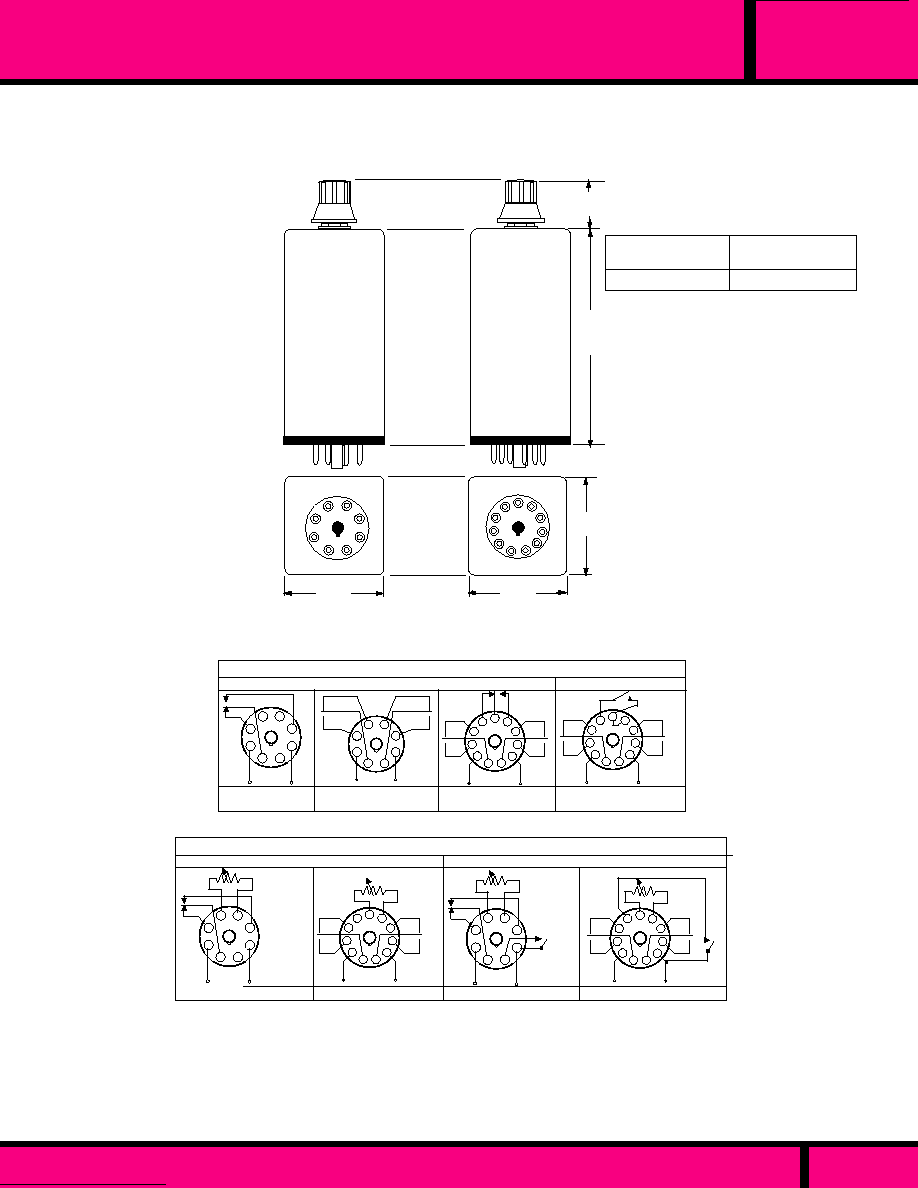
PAGE 128
WEBSITE: www.magnecraft.com EMAIL:info@magnecraft.com FAX ON DEMAND 1-800/891-2957, DOCUMENT 100
OCTAL 8 & 11 PIN TIME DELAY RELAY
SERIES
326/327
A
1.375
(34.9)
.625
(15.87)
1.375
(34.9)
1
2
3
4
5
6
7
9
11
10
8
1.375
(34.9)
5
6
7
8
1
2
3
4
Knob not on
fixed or remote
models
FIXED OR REMOTE
STYLE 326 Only
ADJUSTABLE
WITH KNOB STYLE
2.25 (57.15)
3.0 (76.2)
Dimensions shown are in INCHES and (millimeters)
4
1
2
3
5
6
7
8
INPUT
INPUT
2
v
w
4
1
3
5
6
7
8
v
w
1
11
10
9
8
7
6
4
3
2
5
v
w
v
w
INPUT
+
-
+
-
+
-
1
11
10
9
8
7
6
4
3
2
5
v
w
v
w
INPUT
+
-
External
Switch
326XCX48P
326XBX48P
326XAX48P
SLOW OPERATE
SLOW RELEASE
Jumper
327XBX48P-K
�
�
�
��
OUTLINE DIMENSIONS
WIRING DIAGRAMS
D D
(VIEWED FROM PIN END)
Non Standard
MODELS WITH INTERNAL TIMING RESISTOR
327XBX48P-R
1
11
10
9
8
7
6
4
3
2
5
v
w
v
w
INPUT
+
-
SLOW RELEASE
MODELS WITH EXTERNAL (REMOTE) TIMING RESISTOR
4
1
2
3
5
6
7
8
INPUT
+
-
326XAX48P-R
External
Resistance
D
SLOW OPERATE
1
11
10
9
8
7
6
4
3
2
5
v
w
v
w
INPUT
+
-
326XBX48P-R
External
Resistance
D
4
1
2
3
5
6
7
8
INPUT
-
+
327XAX48P-R
D
External
Resistance
D
External
Resistance
External
Switch
External
Switch
D
External Resistor for remote timing adjustment on models 326 or
327 with code R.
�
This Diagram also applies to fixed time (code F) models.
��
Duplicates wiring of some similar relays made by others.
D
D
Observe Polarity on DC input models
8 PIN OCTAL BASE
11 PIN OCTAL BASE
DIMENSION A

236/237/238
SERIES
12 PIN, 10 AMP, TIME DELAY RELAY
PAGE 129
WEBSITE: www.magnecraft.com EMAIL:info@magnecraft.com FAX ON DEMAND 1-800/891-2957, DOCUMENT 100
236 ABX P 020 120A
Typical Part Number
Code 012**- 12 Second timing not available on 237 & 238 models.
(F * Models) - timing code does not apply. Specify single delay time requirement.
Example of typical fixed time delay relay part number- 236XBXP-3.5F-120A
(ON DELAY, DPDT, 3.5 SEC FIXED, 120 VAC INPUT POWER).
NOTES:
1. 236,237,238 - External resistor (to program time delay) or jumper (for
built-in timing) must be connected to terminals 8 & 9.
2. 237 models require an external control switch between terminals 5 & 6.
3. 238 switches contacts when input power is applied and starts timing.
Contacts switch back to original position at end of timing cycle. Power must
be removed to reset timer. If input power is interupted during the timing
cycle, timing ends immediately and the relay resets.
4. Dielectric withstanding voltage testing of the Control circuit may damage
the solid state components.
SEE SECTION 10 FOR MATING SOCKETS
GENERAL SPECIFICATIONS
The Series 236, 237 and 238 Time Delay Relay consists
of a standard 219 industrial relay and a solid state timing
module to provide delayed transfer of relay contacts after
application of power or activation of control switch. The
relay and timing module are enclosed in a flame resistant
polycarbonate cover.
UL Recognized
File No. E13224
SERIES 236 ON DELAY, 237 OFF DELAY & 238 BATCH CONTROL
INTERVAL (SEE NOTE 3)
AC OR DC INPUT
DPDT OR DPDT WITH 1 N.O. CONTACT ON SERIES 236 & 238
12 PIN PLUG-IN WITH LOCKING CLIP
TIMING: SCREWDRIVER ADJUSTABLE OR FIXED
AC: 24 to 240, DC: 12 to 125
AC - 85% of Nominal
DC - 80% of Nominal
110% of nominal voltage
Silver Cadmium Oxide.
10 Amps @ 120 VAC res.
10 Amps @ 28 VDC
DC:
�
3%: @ 20�C. AC:
�
3% +16 mS
@ 20�C.
Adjustable:
�
10% Within temperature
& voltage range. Fixed:
�
10% @ 25�C
100 mS (for timing cycle up to 60 sec.
150 mS for timing cycle 60 to 300 sec.
500 V rms across open contacts,
1500 V rms between output contacts
and ground (Locking clip). (See note 4).
1000 Megohms min. @ 500 VDC.
5 mS, 0 to 2000 V 20 uSec peak
No false contacting if power is
interupted during timing.
DC operated are polarity protected. but
will not operate if polarity is reversed.
- 10�C to +70 �C
10 Million Operations no load
100,000 Operations @ Rated Load.
Clear Polycarbonate
8.6 oz approx. (244 g)
Series
236 - ON DELAY
237 - OFF DELAY
238 - BATCH CONTROL INTERVAL
Contact Arrangements
ABX (DPDT & 1 N.O. Contact) 236 &
238 only).
XBX (DPDT)
Mounting Options
P (Plug-in)
Timing Ranges
0.2 - 12 Sec - Code 012**
0.2 - 20 Sec - Code 020
2.0 - 200 Sec - Code 200
Adjustment Options
Adjustment Screw) - No Code
Fixed Delay - Specify Fixed Time & Code F *
Operating Voltage
AC; 24, 48, 120, 240 (Add "A" )
DC; 12, 24, 48, 115-125 (Add "D")
Struthers-Dunn
INPUT
Nominal Voltage:
Minimum Oper. Voltage:
Max. allowed voltage:
CONTACTS
Contact Material:
Rating:
OPERATIONAL CHARACTERISTICS
Repeatability:
Accuracy:
Min. waiting time before starting
next cycle (Reset Time):
INSULATION CHARACTERISTICS
Dielectric Strength:
Insulation Resistance:
Transient Protection:
False Contacting:
Inverse polarity protection:
ENVIRONMENTAL CAPABILITIES
Ambient Temperature Rating:
LIFE EXPECTANCY
Mechanical:
Electrical:
MISCELLANEOUS
Enclosure:
Weight:

PAGE 130
WEBSITE: www.magnecraft.com EMAIL:info@magnecraft.com FAX ON DEMAND 1-800/891-2957, DOCUMENT 100
236/237/238
SERIES
12 PIN, 10 AMP, TIME DELAY RELAY
.313
(7.95)
3.75
(95.2)
4.56
(115.8)
OUTLINE DIMENSIONS
Dimensions shown are in INCHES and (millimeters)
7
6
12
1
-
+
TIMING
MODULE
TIMING
MODULE
1
12
�
Jumper or
External Resistor
INPUT
External
control switch
INPUT
�
Jumper or
External Resistor
236ABXP
237XBXP
Viewed from Top of Relay
12
1
6
7
2.625
(66.6)
1.468
(37.2)
Screwdriver adjust not
on fixed models.
�
If the jumper wire shown in each
diagram is replaced by a resistor,
delay time will be added to that
which is produced by an internal
fixed resistor on fixed time models
(code F) or any setting on screwdriver
adjustable models. See timing resistance
chart above. Relay will not operate without
a jumper or resistor. Also see note 1.
1
12
TIMING
MODULE
�
Jumper or
External Resistor
INPUT
OFF DELAY
ON DELAY
DOUBLE POLE DOUBLE
THROW WITH
NORMALLY OPEN CONTACT
LOCKING CLIP
236 RANGE: O.2 TO 12 SEC
20K OHMS PER EA.3 SEC
100 K OHMS MAX.
236 RANGE: 0.2 TO 20 SEC
100K OHMS PER EA.7 SEC
500 K OHMS MAX
237/238 RANGE: 0.2 TO 20 SEC.
100K OHMS PER EA.6 SEC
500 K OHMS MAX.
236 RANGE: 2.0 TO 200 SEC
200K OHMS PER EA.60 SEC
1 MEG OHM MAX.
237/238 RANGE: 2.0 TO 200 SEC
200K OHMS PER EA.55 SEC.
1 MEG OHM MAX.
�
TIMING
*
RESISTANCE CHART
*
USE RESISTOR RATED 1/4 WATT
OR MORE.
EXAMPLE
WIRING DIAGRAMS
BATCH CONTROL
INTERVAL
(SEE NOTE 3)
7
-
-
7
+
6
6
+
DOUBLE POLE DOUBLE THROW
238XBXP
DOUBLE POLE DOUBLE THROW

ON DELAY FUNCTION
The series 246 & 247 Time Delay Relays are
a ON-Delay or Off Delay Function times, with
timing ranges from 0.1 to 300 Seconds. The
246 Timer comes in either 2 - 4 poles, and
the 247 comes in 2 & 3 Pole models. Both
timers incorporate a class 219 relay along
with a Solid State timing module. Both timers
have a large choice of options and switch up
to 30 amp loads.
Series 246 CSA Certified
R
R
Listed when used with
Type 29390 Socket
UL Recognized
File No. 13224
Series
246 - On Delay, Plug-in 2-4 Pole
247 - Off Delay, Plug-in, 2 & 3 Pole
Contact Arrangements
XBX (2 Form "C")
XCX (3 Form "C")
ABA (1 Form A & 2 Form C & 1 Form B).
BBX (2 Form A & 2 Form C) 246 Only.
Standard Features
Plug-in With Polycarbonate Cover - Code P
Options
Indicator Lamp- Code L
Manual Actuator - Code M
Bifurcated Contacts (5 Amps max) - Code 33
Permanent Magnet, Blowout Code 69
Timing Ranges
0.1 - 1.0 Sec - Code 001
0.2 - 2.0 Sec - Code 002
1.0 - 10 Sec - Code 010
3.0 - 30 Sec - Code 030
6.0 - 60 Sec - Code 060
18 - 180 Sec - Code 180
30 - 300 Sec - Code 300
Adjustment
Adjustment Knob) - No Code
Fixed - Timing Code does not apply. Ex. 3F = 3 Sec
Fixed) Code F
Remote Adj. (Ext Pot Required) - Code R
Operating Voltage
AC; 24, 48, 120, 240 (Add "A" )
DC; 12, 24, 48, 110-125 (Add "D")
247 XBX P L - 010 - 120A
Typical Part Number
246XBXP
1
12
7
6
TIME
MOD
246ABAP
1
12
7
6
TIME
MOD
246BBXP
1
12
7
6
TIME
MOD
247XBXP
1
12
7
6
TIME
MOD
247XCXP
EXT. TRIGGER
EXT. TRIGGER
OFF DELAY FUNCTION
1
12
7
6
TIME
MOD
GENERAL SPECIFICATIONS SERIES 246 & 247 TIMER
INPUT
Coil Voltage
Minimum Operate Voltage:
Max. allowed voltage:
CONTACTS
Contact Material:
OPERATIONAL CHARACTERISTICS
Repeatability:
Accuracy:
Recycle Time:
False Contacting:
Polarity Protection:
INSULATION CHARACTERISTICS
Dielectric Strength:
All Mutually Insulated Points:
Transient Protection:
Insulation Resistance:
ENVIRONMENTAL CAPABILITIES
Ambient Temperature Rating:
LIFE EXPECTANCY
Mechanical:
Electrical:
MISCELLANEOUS
Enclosure:
Weight:
AC - 85% of Nominal
DC - 80% of Nominal
110% of nominal voltage
Silver Cadmium Oxide. - Gold Diffused
�
3% @ 25�C (AC +16 mS)
Adjustable
�
10% Within temperature &
voltage range.
100 mS up to 60 Sec., 150 mS 60 to 300 Sec.
No false contacting if power is interrupted
during timing cycle.
DC inputs
500 V rms across open contacts
1500 V rms between current carrying
parts & Parts to Ground.
5 mS 0 to 2000V, 20 uSec peak
1000 M
min. @ 500 VDC
AC: -10�C to +45�C @ Rated Operation.
DC: -10�C to +70 �C
10 Million Operations no load
100,000 Operations @ Rated Load.
500,000 @ 1/2 Rated Load.
Clear polycarbonate
8 oz. (227 g)
WEBSITE: www.magnecraft.com EMAIL:info@magnecraft.com FAX ON DEMAND 1-800/891-2957, DOCUMENT 100
PAGE 131
SERIES
246 & 247
INDUSTRIAL 10 AMP, ON-DELAY & OFF DELAY TIMER
12
1
6
7
2.625
(66.6)
1.468
(37.2)
3.75
(95.2)
4.56
(115.8)
.678
(17.2)
Dimensions shown are in
INCHES and (millimeters)
SEE SECTION 10
FOR
MATING SOCKETS
SERIES 246 & 247
�
3% REPEATABILITY
PLUG-IN WITH SELF
LOCKING CLIP
Struthers-Dunn
24 VDC
120 VAC
240 VAC
28 VDC
125 VDC
125 VDC (SM)
125 VDC (DM)
250 VDC (SM)
250 VDC (DM)
10A
10A
10A
10A
10A
10A
10A
10A
10A
30A
30A
30A
30A
30A
30A
30A
30A
30A
10A
10A
5A
10A
0.5A
1.5A
4A
0.5A
1.5A
10A
3A
1A
3A
0.1A
0.5A
1.5A
150mA
0.5A
Voltage
Carry
Make
Resistive Inductive
CONTACT LOAD SPECIFICATIONS
For Versions with suffix "69"
Permant Magnet Blowouts

C L A S S
235
ADJUSTABLE CURRENT SENSING RELAY
SPECIFICATIONS CLASS 235 CURRENT SENSOR
CURRENT SENSING:
Sense Current Range:
Repeatability:
Input Current:
Current Sensor Resistance:
Temperature Range Operate:
Temperature Range Storage:
CONTACTS
Contact Combinations:
Contact Rating
Transient:
LIFE EXPECTANCY;
Electrical
Mechanical:
DIELECTRIC STRENGTH
Coil to Contacts:
Across Open Contacts:
MECHANICAL
Terminals:
Mounting:
Mounting Bracket:
Enclosure:
Weight:
1.5 to 15 Amperes
�
2% at constant Voltage & Temperature
�
10% over Voltage & Temperature Range.
15 mA (1.7 VA)
5 Milliohms
- 10�C to + 55�C
- 40�C to + 85�C
SPDT (1 Form C)
10 Amps @ 120 VAC, 6 Amps @ 28 VDC.
2000 V rms for 5 Microseconds
200,000 Operations @ Rated Load
5,000,000 Operations @ No Load
2500 V rms
500 V rms
Choice of 1/4" or 3/16" Quick Connect
terminals.
6-32 Tapped Hole & anti rotation Tab or
Plug-in with 3/16" terminals.
Optional.
Polycarbonate dust cover.
4 oz. (113 g) approx.
CLASS 235
CURRENT SENSOR
�
2 % REPEATABILITY
SPDT, 10 AMP CONTACTS
FIELD ADJUSTABLE CURRENT
SETTINGS.
Ul Recognized
File No. 62636
ANTI-ROTATION TAB
1
2
3
4
5
6
7
8
A
B
9
1.40
(35.7)
.312
(7.9)
.625
(15.8)
2.90 Max.
(73.8)
1.53
(38.8)
.875
(22.2)
1.31
(33.3)
6-32 TAPPED HOLE
(1/4" Terminal Style)
OUTLINE DIMENSIONS
Dimensions are Shown In Inches and (Millimeters)
4
5
7
1
2
6
9
3
B
A
INPUT
8
Continuous Voltage must
be supplied to Input.
LOAD
VIEWED FROM TERMINAL SIDE
WIRING DIAGRAM
SEE SECTION
10
FOR MATING SOCKETS
W235ACX-2
W235ACX-3
NOMINAL
INPUT
VOLTAGE
TERMINAL
SIZE
CURRENT
RANGE
PART NUMBERS SHOWN ALSO AVAILABLE THRU STOCKING DISTRIBUTION.
PART NUMBERS
120 VAC
120 VAC
NOTE: 3/16" (.187) TERMINALS ARE SOCKET MOUNTABLE.
1/4" (.250) TERMINALS, NO SOCKET AVAILABLE FOR THIS STYLE.
PAGE 132
WEBSITE: www.magnecraft.com EMAIL:info@magnecraft.com FAX ON DEMAND 1-800/891-2957, DOCUMENT 100
1.5 to 15 Amps
1.5 to 15 Amps
1/4" (.250)
3/16" (.187)
The Class 235 Current Sensing Relay
combines a Solid State Sensor with a
SPDT, 10 Amp relay. The Sensor is field
adjustable for detecting AC Current levels
in equipment. The sensor is non-latching
and has no time delay.
SUPPLY
VOLTAGE

1
12
7
SENSING
MODULE
6
1
12
7
6
SENSING
MODULE
RESISTOR
12
SENSING MODULE
1
6
A B C N
7
RESISTOR
THREE PHASE -349XBXP
SINGLE PHASE -349ABXP
SINGLE PHASE -349BBXP
INPUT
INPUT
Differential 4.0 volts
�
1 Volt nonadjustable
GENERAL SPECIFICATIONS SERIES 349 SENSOR
Adjustment 85 to 135 VAC, 50 to 400 Hz
De-energized -15 mA, Energized - 50 mA
Silver Cadmium Oxide. - Gold Diffused
25 Milliseconds
25 Milliseconds
500 V rms
1500 V rms
1000 Megohms min. @ 500VDC.
-10�C to +60�C @ Rated Operation.
20 Million Operations no load
100,000 Operations @ Rated Load.
500,000 @ 1/2 Rated Load.
Clear polycarbonate
10 oz. (284 g)
INPUT
Module Voltage:
AC Current Drain:
CONTACTS
Contact Material:
OPERATIONAL CHARACTERISTICS
Operate time:
Release Time:
INSULATION CHARACTERISTICS
Dielectric Strength
Across Open Contacts:
All Mutually Insulated Points:
Insulation Resistance
ENVIRONMENTAL CAPABILITIES
Ambient Temperature Rating:
LIFE EXPECTANCY
Mechanical:
Electrical
:
M I S C E L L A N E O U S
Enclosure:
Weight:
24 VDC
120 VAC
240 VAC
28 VDC
125 VDC
125 VDC (SM)
125 VDC (DM)
250 VDC (SM)
250 VDC (DM)
10A
10A
10A
10A
10A
10A
10A
10A
10A
30A
30A
30A
30A
30A
30A
30A
30A
30A
10A
10A
5A
10A
0.5A
1.5A
4A
0.5A
1.5A
Voltage
Carry
Make
Resistive Inductive
For Versions with suffix "69"
Permanent Magnet Blowouts
CONTACT LOAD SPECIFICATIONS
349 ABXP & XBXP Style the
Differential Adjustment is
Externally Adjustable from 3
to 14 Volts.
10A
3A
1A
3A
0.1A
0.5A
1.5A
150mA
0.5A
12
1
6
7
2.625
(66.6)
1.468
(37.2)
Dimensions shown are in INCHES and (millimeters)
.313
(7.95)
3.75
(95.2)
4.56
(115.8)
OUTLINE DIMENSIONS
Series
349 Sensor -Plug-in, Over/Under
Voltage Relay, 10A, 2 -4 poles
Contact Arrangement & Function
BBX - 2 Form A & 2 Form C, (Single Phase)
4V
�
1V Fixed.
ABX - 1 Form A & 2 Form C, (Single Phase)
Ext. Adjustment, 3 to 14V
XBX - 2 Form C, (3 Phase)
External Adjustment, 3 to 14V
Standard Features
Plug-in With Polycarbonate Cover - Code P
Options
Indicator Lamp- Code L
Manual Actuator - Code M
Bifurcated Contacts (5 Amps max) - Code 33
Permanent Magnet, Blowout Code 69
Operating Voltage
AC; 85 to 135 (Add "A" )
DC; Consult Factory
Note: For non-Standard Differential Consult Factory
Typical Part Number
349 BBX P L33- 85-135A
PAGE 133
SERIES
349
OVER/UNDER VOLTAGE SENSING, 10 AMP, 2-4 POLE
WEBSITE: www.magnecraft.com EMAIL:info@magnecraft.com FAX ON DEMAND 1-800/891-2957, DOCUMENT 100
SEE SECTION 10
FOR
MATING SOCKETS
The Series 349 Under/Over Voltage Sensing
Relay incorporates a Series 219 relay and an
Electronic Module. Pull-in Voltage is adjustable
between 85 and 135 VAC for frequencies from
50 to 400 Hz. Models available for Single and
Three Phase sensing with differential (between
pull-in and Dropout) Adjustable from 2 to 14 Volts
by external fixed or adjustable resistor. Single
Phase relays are also available with standard 3
volt fixed differential and other fixed values up to
14 volts, on special order.
SERIES 349
FREQUENCY 50 to 400 Hz
PULL-IN ADJUSTABLE
BETWEEN 85 to 135 VAC
10 AMP CONTACTS
Struthers-Dunn

SEE SECTION 10
FOR MATING SOCKETS
PAGE 134
WEBSITE: www.magnecraft.com EMAIL:info@magnecraft.com FAX ON DEMAND 1-800/891-2957, DOCUMENT 100
ADJUSTABLE VOLTAGE SENSING RELAY
236
C L A S S
�
1 % REPEATABILITY
DPDT, 10 AMP CONTACTS
FIELD ADJUSTABLE
�
1 % REPEATABILITY
SPDT, 13 AMP CONTACTS
FIELD ADJUSTABLE
SPECIFICATIONS CLASS 236 CURRENT SENSOR
VOLTAGE SENSING:
Nominal Input:
Adjustment Range:
Repeatability:
Input Current:
Current Sensor Resistance:
Temperature Range Operate:
Temperature Range Storage:
CONTACTS
Contact Combinations:
Contact Rating
Contact Life Electrical:
Contact Life Mechanical:
Transient:
Noise Immunity:
DIELECTRIC STRENGTH
Breakdown:
Coil to Contacts:
Across Open Contacts:
MECHANICAL
Terminals:
Enclosure:
Power "ON" Indicator:
Weight:
120,240,480 VAC 50/60Hz, 24VAC, 24 VDC. Other
AC & DC Voltages Available.
Pull-in 75% to 115% of Nominal Voltage.
Dropout 75% to 95% of Pickup setting.
�
1% @ constant Voltage & Temperature
15 mA (1.7 VA)
Relay "Off" 2 mA max. Relay "On" 22 mA max. @ 120AC (2.7 VA)
12 mA 240AC max. (2.9VA), 7 mA max. 480 AC (3.41 VA)
- 30�C to + 55�C
- 40�C to + 85�C
SPDT (1 Form C), DPDT (2 Form "C")
SPST: 13 Amps @ 240 VAC, 28 VDC Res.
1/3 HP @ 120 VAC, 1/2 HP @ 240/480 AC,
3 AMPS @ 480 VAC, NEMA B300 Pilot Duty
DPDT: 10 AMPS @ 240 VAC/28 VDC Res.
1/3Hp @ 120 VAC, 1/2 Hp 240 VAC
NEMA B300 Pilot Duty.
SPDT: 100,000 Operations @ 13 Amps, 240AC Res.
DPDT: 100,000 Operations @ 10 Amps, 240AC Res.
SPDT:5,000,000 Operations
DPDT: 50,000,000 Operations.
UL 508 Surge 5000 V for 50 microseconds
NEMA ICS2-230, 2500 VAC
UL 508 Surge 5KV 1.2 x 50 Microseconds.
2500 V rms
1000 V rms
3/16" (.187) Quick Connect terminals. or 8 Pin Octal base
Polycarbonate dust cover.
L.E.D. ( Green)
4 oz. 124.4 g, 5 oz 155.5g (8 pin octal)
CLASS 236
VOLTAGE SENSOR
Ul Recognized
File No. 62636
The Class 236 Voltage Sensing Relay combines a Solid State Sensor
with a SPDT, 13 Amp or DPDT 10 Amp relay.
The Sensor is field adjustable for Pull-in & Dropout .
The 236 can be used either as a over or under voltage detecting relay.
The sensor is non-latching and has no time delay.
Applications: Brownout protection, warning of under voltage conditions
and Over voltage protection. Prevents equipment burnout.

ADJUSTABLE VOLTAGE SENSING RELAY
C L A S S
236
4
5
7
1
6
9
3
B
A
8
2
INPUT
2
3
5
6
8
B
9
1.53
(38.8)
Pull-in
Dropout
1
4
7
A
L.E.D
1.40
(35.7)
.312
(7.9)
L.E.D
L.E.D
Dimensions are Shown In Inches and (Millimeters)
2.93
(74.4)
1.75
(44.4)
1
2
7
8
4
3
5
6
L.E.D
2.37
(60.3)
.
562 (14.2)
FIGURE "A"
INPUT
2
v
w
4
1
3
5
6
7
8
v
w
SQUARE BASE
Continuous Voltage
must be supplied to Input.
8 PIN OCTAL
Continuous Voltage
must be supplied to Input.
OUTLINE DIMENSIONS
2.90 Max.
(73.8)
FIGURE "B"
-
+
WIRING DIAGRAMS
VIEWED FROM PIN END
WIRING DIAGRAMS
VIEWED FROM PIN END
Screw Driver Adjustable with
Graduated scale.
OUTLINE DIMENSIONS
Dimensions are Shown In Inches and (Millimeters)
W236ACX-1
W236ACX-2
W236ACX-4
W236ACPX-1
W236ACPX-4
W236CPX-1
VOLTAGE
PULL-IN
RANGE
VOLTAGE
DROP-OUT
RANGE
90 to 138 VAC
18 to 28VAC
18 to 28 VDC
NOMINAL
INPUT
VOLTAGE
B
B
B
A
A
A
PART NUMBERS
120 VAC
208/220 240 VAC
480 VAC
120 VAC
24 VAC
24 VDC
90 to 138 VAC
180 to 276 VAC
360 to 552 VAC
92 to 140 VAC
20 to 30 VAC
20 to 30 VDC
FIG.
CROSS REFERENCE
TO
POTTER & BRUMFIELD
CSJ-38-70010
CSJ-38-30010
CSL-38-30010
PART NUMBERS SHOWN ALSO AVAILABLE THRU STOCKING DISTRIBUTION.
-
-
-
PAGE 135
WEBSITE: www.magnecraft.com EMAIL:info@magnecraft.com FAX ON DEMAND 1-800/891-2957, DOCUMENT 100
75% to 95%
of Pickup
Voltage
Setting

6
POWER RELAYS
AND
CONTACTORS
15 TO 200 AMPERES
S E C T I O N
6
Page 136
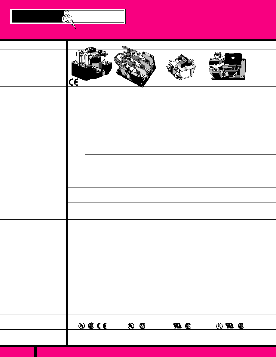
DIELECTRIC STRENGTH
RELAY SERIES
FEATURES
COIL DATA
GENERAL DATA
APPROVALS
AC - VOLTAGE:
DC - VOLTAGE:
POWER
VA,: (VAC)
WATTS,: (VDC)
INSULATION
CHARACTERISTICS
AMBIENT TEMPERATURE
OPERATIONAL:
STORAGE:
TIMING VALUES
OPERATE:
RELEASE:
LIFE
MECHANICAL:
ELECTRICAL:
DIMENSIONS
SILVER CADMIUM OXIDE,
50 MILLIOHMS (INITIAL)
2.53 X 2.50 X 2.43-3.12
D W L
2200 V rms
24, 120 & 240 VAC
6, 12, 24, 110 VDC
10 VA
2.0 WATTS
- 30� C to + 50� C (AC.)
- 30� C to + 60� C (DC)
- 30� C to + 100� C
40 MILLISECONDS
35 MILLISECONDS
5 MILLION OPERATIONS
100,000 OPERATIONS
CONTACT DATA
CONTACT CONFIGURATION:
MAXIMUM ALLOWABLE
CONTACT LOAD:
CONTACT MATERIAL:
CONTACT RESISTANCE:
SEE CATALOG PAGE
30 AMPS UP TO 300
VAC, 28 VDC, (STD.)
BOX TERMINAL
SPST-DM -UP TO 50A.
WITH MAGNETIC
BLOWOUT UP TO
20AMP DC
D W L
PANEL MOUNT OPEN
STYLE CONSTRUCTION
3PDT CONTACT
CONFIGURATIONS
UP TO 30 AMP SWITCH-
ING
SCREW TERMINALS
INSULATED ARMATURE
TO 600V AVAILABLE
25 AMP @120-240VAC
17AMP @ 277VAC
10AMP @ 600VAC
30AMP @ 30VDC
3 P D T
SILVER CADMIUM OXIDE
50 MILLIOHMS (INITIAL)
2500 V rms
6 to 480 VAC
6 to 220 VDC
11 VA
4.0 WATTS
- 55� C to + 45� C (AC)
- 55� C to + 80� C (DC)
30 MILLISECONDS
15 MILLISECONDS
10 MILLION OPERATIONS
100,000 OPERATIONS
QUALIFIED
PANEL MOUNT, OPEN
STYLE CONSTRUCTION
MULTI CONTACT
CONFIGURATIONS UP
TO 50 AMPS SWITCHING.
MAGNETIC BLOWOUT
FOR DC SWITCHING
CLASS "B" INSULATION
SYSTEM
SCREW & BOX TERMI-
NALS
425
199
2.30 X 2.50 X 3.24
PAGE 137
WEBSITE: www.magnecraft.com EMAIL:info@magnecraft.com FAX ON DEMAND 1-800/891-2957, DOCUMENT 100
PANEL MOUNT, COMPACT
SIZE, OPEN STYLE CON-
STRUCTION.
MULTI CONTACT
CONFIGURATIONS.
SCREW TERMINALS.
OPTIONAL HIGH VOLTAGE
AND HIGH INRUSH CON-
TACTS, Q.C. TERMINALS,
MAGNET BLOWOUT.
SPECIAL LOW POWER
COILS AVAILABLE.
SEE CATALOG PAGE
15 AMPS @ 120VAC 1/2HP
10 AMPS @ 240VAC 1HP
15 AMPS @ 30VDC
SILVER CADMIUM OXIDE
50 MILLIOHMS (INITIAL)
1500 V rms
6 to 240 VAC
6 to 125 VDC (Use
power resistor
for 250VDC)
6 V A
3.5 WATTS
D W L
1.75 X 1.87 X 2.75
415
- 45� C to + 55� C
- 45� C to + 55� C
25 MILLISECONDS
10 MILLISECONDS
AC- 50M, - DC-100M OPER'S.
200,000 OPERATIONS
88UKD
COMPACT OPEN STYLE
RELAY WITH 6-32 TAPPED
HOLE & ANTI-ROTATION
TAB FOR PANEL MOUNT.
SWITCHES UP TO 3O
AMPS
1/4" SPADE LUG TERMI-
NALS
DOUBLE MAKE CONTACTS
SPST-N.0. (DM)
30 AMPS @
3 0 0 V A C / 2 8 V D C
5 AMPS 600VAC
SILVER ALLOY
GOLD FLASHED
50 MILLIOHMS (INITIAL)
3000 V rms
- 10� C to + 50� C (AC)
- 10� C to + 60� C (DC)
5 MILLION OPERATIONS
100,000 OPERATIONS
D W L
.1.40 X 1.25 X 1.93
24, 120 & 240 VAC
12, 24 & 110 VDC
3 VA
1.5 WATTS
PAGE 140 THRU 146
PAGE NUMBER
PAGE 147
PAGE 148
PAGE 149, 150
Magnecraft
Struthers-Dunn
POWER RELAYS & CONTACTORS
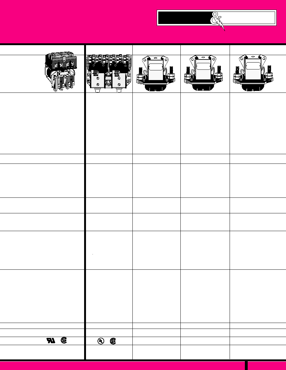
CONTACTORS
D W L
575
3.00 X 5.25 X 4.43
2 COIL, MOTOR REVERS-
ING CONTACTOR
MECHANICAL INTERLOCK
COILS
SCREW TERMINALS WITH
OPTIONAL 5A AUXILIARY
SWITCHES AVAILABLE.
RATED UP TO 7.5 HP
24 to 550VAC
12 to 240 VDC
22 VA
10 WATTS
2500 V rms
30 AMPS @120 VAC, 1.5HP
30 AMPS @240VAC, 3HP
15 AMPS @480 VAC, 7.5HP
15 AMPS @600 VAC, 7.5HP
15 AMPS @ 115VDC
2 AMPS @ 230 VDC
SILVER CADMIUM OXIDE
100 MILLIOHMS (INITIAL)
1.84 X 2.34 X 2.50
1500 V rms
-
12, 28, 48 VDC
-
9 WATTS
101
50 AMPS @
120/240VAC,
30 VDC
SILVER CADMIUM OXIDE
50 MILLIOHMS (INITIAL)
D W L
SEE CATALOG PAGE
1500 V rms
SILVER CADMIUM OXIDE
50 MILLIOHMS (INITIAL)
-
12, 28, 48 VDC
-
11.6 WATTS
100 AMPS @
120/240VAC,
30 VDC
SEE CATALOG PAGE
102
D W L
200 AMPS @
120/240VAC,
30 VDC
103
SEE CATALOG PAGE
HEAVY DUTY DC SOLENOID
STYLE CONTACTOR.
CHOICE OF CONTACT
CONFIGURATIONS
RATED UP TO 50 AMPS
CONTINUOUS
CONTACTS ENCLOSED
WITH MOLDED PLASTIC
COVER.
AC COILS AVAILABLE
HEAVY DUTY DC SOLENOID
STYLE CONTACTOR.
CHOICE OF CONTACT
CONFIGURATIONS
RATED UP TO 100 AMPS
CONTINUOUS
CONTACTS ENCLOSED
WITH MOLDED PLASTIC
COVER.
AC COILS AVAILABLE
HEAVY DUTY DC SOLENOID
STYLE CONTACTOR.
CHOICE OF CONTACT
CONFIGURATIONS
RATED UP TO 200 AMPS
CONTINUOUS
CONTACTS ENCLOSED
WITH MOLDED PLASTIC
COVER.
AC COILS AVAILABLE
6 POLE-DM (3 PER COIL)
- 40� C to + 50� C (AC)
- 40� C to + 50� C (DC)
60 MILLISECONDS
30 MILLISECONDS
500,000 OPERATIONS
100,000 OPERATIONS
- 45� C to + 65� C (DC)
60 MILLISECONDS
30 MILLISECONDS
500,000 OPERATIONS
100,000 OPERATIONS
- 45� C to + 65� C (DC)
60 MILLISECONDS
30 MILLISECONDS
500,000 OPERATIONS
100,000 OPERATIONS
- 45� C to + 65� C (DC)
60 MILLISECONDS
30 MILLISECONDS
500,000 OPERATIONS
100,000 OPERATIONS
D W L
2.09 X 3.12 X 3.00
2.65 X 4.25 X 3.00
-
12, 28, 48 VDC
-
14 WATTS
1500 V rms
SILVER CADMIUM OXIDE
50 MILLIOHMS (INITIAL)
275
SILVER CADMIUM OXIDE
100 MILLIOHMS (INITIAL)
2500 V rms
12 to 240 VAC
12 to 120 VDC
16.7 VA
4.9 WATTS
- 45� C to + 50� C (AC)
- 45� C to + 70� C (DC)
50 MILLISECONDS
30 MILLISECONDS
500,000 OPERATIONS
100,000 OPERATIONS
D W L
2.75 X 2.985 6 X 3.62
15 AMPS @120VAC/1HP
10AMPS @ 240VAC/1.5HP
5AMPS @ 480/600/3HP
15AMPS @ 30VDC
5AMPS @ 125VDC
1AMP @ 250VDC
6 POLE-DM (3 PER COIL)
2 COIL, COMPACT MOTOR
REVERSING CONTACTOR.
1/4" DUAL Q.C. TERMINALS
WITH UP TO 4 OPTIONAL
AUXILIARY SWITCHES.
ENCAPSULATED COIL
USED FOR AC OR DC MODELS
MECHANICAL INTERLOCK,
CENTER OFF WHEN BOTH
COILS NOT ENERGIZED.
PAGE 138
WEBSITE: www.magnecraft.com EMAIL:info@magnecraft.com FAX ON DEMAND 1-800/891-2957, DOCUMENT 100
PAGE 151, 152
PAGES 153, 154
PAGES 155, 156
PAGES 155, 156
PAGES 155, 156
Magnecraft
Struthers-Dunn
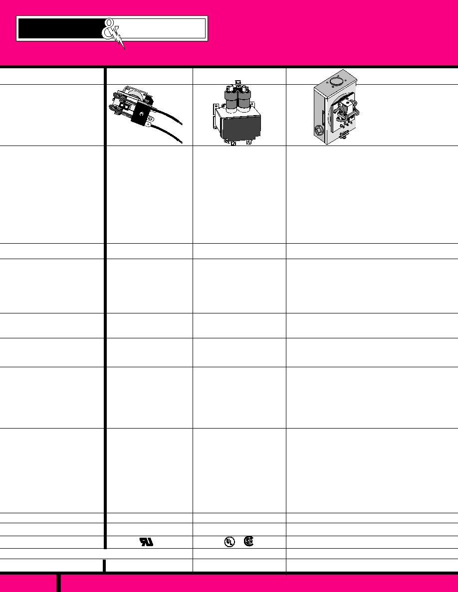
PAGE 139
WEBSITE: www.magnecraft.com EMAIL:info@magnecraft.com FAX ON DEMAND 1-800/891-2957, DOCUMENT 100
CONTACT CONFIGURATION:
MAXIMUM ALLOWABLE
CONTACT LOAD:
CONTACT MATERIAL:
CONTACT RESISTANCE:
AMBIENT TEMPERATURE
OPERATIONAL:
AC - VOLTAGE:
DC - VOLTAGE:
P O W E R
VA, (VAC):
WATTS, (VDC):
INSULATION
CHARACTERISTICS
DIELECTRIC STRENGTH:
APPROVALS
DIMENSIONS
GENERAL DATA
COIL DATA
CONTACT DATA
S T O R A G E :
TIMING VALUES
OPERATE:
RELEASE:
L I F E
MECHANICAL:
ELECTRICAL:
RELAY SERIES
1.37 X 1.00 X 2.10
214 (GFI)
SMALL OPEN STYLE
GROUND FAULT INTER-
RUPT RELAY.
MAX. OVER LOAD 120
AMPS @ 120VAC
PIERCED SOLDER LUG
TERMINALS WITH #17
AWG SILICONE WIRE
MOUNTING WITH 6-32
TAPPED HOLE & ANTI-
ROTATION TAB
DPDT (2 FORM C)
20 AMPS @ 120/240VAC
20 AMPS @ 30 VDC
120AMPS @ 120VAC
(10 CYCLES)
2000 V rms
- 45� C to + 65� C
15 MILLISECONDS
15 MILLISECONDS
10 MILLION OPERATIONS
100,000 OPERATIONS
D W L
SILVER, CADMIUM OXIDE
50 MILLIOHMS (INITIAL)
6, 12, 24, 120 VAC
6, 12, 24, 110-125 VDC
-
-
3.36 X 3.75 X 5.06
MDR
MERCURY DISPLACEMENT RELAY
(MDR)
UP TO 3 POLES, NO OR NC &
COMBINATIONS OF NO & NC
ENCAPSULATED COIL..
UP TO 100 AMPS SWITCHING
LOW CONTACT RESISTANCE
PANEL MOUNTED VERTICAL
�
15�
1 to 3PST-NO or NC
35 TO 100 AMPS @
120-480VAC.
25-50 AMPS @ 600VAC
100 AMPS, 24-48 VDC
80 AMPS, 120VDC
2650 V rms
- 35� C to + 60� C
50 MILLISECONDS
100 MILLISECONDS
5 MILLION OPERATIONS
100,000 OPERATIONS
D W L
MERCURY
2 MILLIOHMS
120 & 240 VAC
24 VDC
33 VA
9 WATTS
1500 V rms
SILVER CADMIUM OXIDE
50 MILLIOHMS (INITIAL)
12 to 240 VAC
6 to 220 VDC
-
20 WATTS
D W L
- 45� C to + 65� C (DC)
60 MILLISECONDS
30 MILLISECONDS
500,000 OPERATIONS
100,000 OPERATIONS
102, 103
HEAVY DUTY DC SOLENOID STYLE
LIGHTING CONTACTOR, MOUNTS TO
WATT HOUR METER ENCLOSURE.
DPST-NO-DM CONTACT CONFIGURA-
TION.
RATED UP TO 50 & 100 AMPS CONTINU-
OUS DUTY.
CONTACTS ENCLOSED IN MOLDED
PLASTIC COVER.
DC COILS AND AC FULL WAVE
RECTIFIED COILS.
DPST-NO-DM
50 & 100 AMPS @
120/240VAC,
30 VDC
3.0 X 6.0 X 6.0
FEATURES
PAGE NUMBER
PAGE 157
PAGES 165
GENERAL SPECIFICATIONS & APPLICATION DATA:
PAGE 158, 159
PAGE 160 THRU 164
Magnecraft
Struthers-Dunn
POWER , GFI AND MDR RELAYS

OPEN STYLE 30 AMP POWER RELAY
C L A S S
199
PAGE 140
2.43 Max.
(61.7)
2.50
(63.5)
1.87
(47.5)
1.62
41.14
.375
(9.5)
0.187 Dia.
(2 Places)
OUTLINE DIMENSIONS
Dimensions shown in Inch & (Millimeters)
2.18 Max.
(55.37)
UP
VERTICAL MOUNTING
RECOMMENDED WITH
CONTACTS UP
CLASS 199 SPDT
30 AMP - 1-1/2 Hp
CLASS "B" COIL
INSULATION SYSTEM
COMPLIES WITH
REQUIREMENTS OF
IEC STANDARDS
947-4-1 AND 947-5-1
LOW VOLTAGE DIRECTIVE
IEC = INTERNATIONAL
ELECTROTECHNICAL COMMISSION
*
*
UL Listed
File No. E43641
AC OPERATED (SPDT)
PART
NUMBERS
120 VAC
12 VDC
24 VDC
-
-
70
290
10 VA
2.0 W
2.0 W
COIL Measured @ 25�C
W199AX-4
W199X-2
W199X-3
DC OPERATED (SPDT)
PRD5AGO-120
PRD5DGO-12
PRD5DGO-24
CROSS
REFERENCE
POTTER &
BRUMFIELD
PART NUMBERS SHOWN ALSO AVAILABLE THRU STOCKING DISTRIBUTION.
*
RELEVANT IEC CONTACT UTILIZATION CATEGORIES
AC-1, AC-3, DC-1, AC-15
SEE SECTION 11, FOR RELEVANT UTILIZATION CATEGORIES
AUXILIARY CONTACTS AND OTHER COIL VOLTAGES ARE
AVAILABLE ON SPECIAL ORDER. CONTACT FACTORY FOR
SPECIAL REQUIREMENTS.
NOMINAL
INPUT
VOLTAGE
NOMINAL
RESIS-
TANCE
(OHMS)
NOMINAL
POWER
SPECIFICATIONS CLASS 199
COIL
Pull-in Voltage:
Dropout Voltage:
Coil Resistance:
Max. Coil Dissipation:
CONTACTS
Contact Combination:
Contact Rating
Contact Material:
TIMING
Operate time:
Release Time:
DIELECTRIC STRENGTH
Between Open Contacts:
Mutually Insulated
Conductive elements:
TEMPERATURE
Operating Range:
Non-Operating Storage
range:
LIFE
Electrical (Rated Load):
Mechanical (No Load):
MISCELLANEOUS
Coil Terminals:
Contact Terminals:
Base Material:
Weight:
80% DC Coils, 85% AC coils of
nominal voltage or Less @ 25�C
10% of Nominal Voltage or More @ 25�C
�
10% @ 25�C
DC Coils-4 Watts Max. Continuous.
SPDT
30 Amps up to 300VAC, 50/60Hz
5 Amps @ 480/600 VAC, 50/60HZ
0.75pF Inductive Load. 1-1/2 HP Motor
Load @ 120 thru 600 VAC, 50/60 Hz.
30 Amps @ 28 VDC Resistive Load
NEMA A 600 Pilot Duty 50/60Hz
Silver Cadmium Oxide, Gold Flashed.
5/16" Diameter Standard.
40 Milliseconds Max. @ Nominal V
30 Milliseconds Max. @ Nominal V
1500 V rms
2200 V rms
(AC) -30�C to +50�C, (DC) -30�C +60�C
-30�C to +100�C
100,000 Operations
5,000,000 Operations
6-32 Binder Head Screws
8-32 Binder Head Screws
Molded Phenolic, UL Recognized
(QMFZ2)
8 oz. - 227 Grams approx. (SPDT)
WEBSITE: www.magnecraft.com EMAIL:info@magnecraft.com FAX ON DEMAND 1-800/891-2957, DOCUMENT 100

OPEN STYLE 30 AMP POWER RELAY
PAGE 141
C L A S S
199
2.50
(63.5)
.375
(9.5)
3.12
(79.2)
1.62
(41.1)
0.187 Dia.
(2 Places)
1.87
(47.5)
OUTLINE DIMENSIONS
Dimensions shown in Inch & (Millimeters)
2.31 Max.
(58.67)
UP
VERTICAL MOUNTING
RECOMMENDED WITH
CONTACTS UP
CLASS 199 DPDT
30 AMP - 1-1/2 Hp
CLASS "B" COIL
INSULATION SYSTEM
*
*
UL Listed
File No. E43641
COMPLIES WITH
REQUIREMENTS OF
IEC STANDARDS
947-4-1 AND 947-5-1
LOW VOLTAGE DIRECTIVE
IEC = INTERNATIONAL
ELECTROTECHNICAL COMMISSION
SPECIFICATIONS CLASS 199
COIL
Pull-in Voltage:
Dropout Voltage:
Coil Resistance:
Max. Coil Dissipation:
CONTACTS
Contact Combinations:
Contact Rating each Pole:
Contact Material:
TIMING
Operate time
Release Time:
DIELECTRIC STRENGTH
Between Open Contacts:
Mutually Insulated
Conductive elements:
TEMPERATURE
Operating Range:
Non-Operating Storage
range:
LIFE
Electrical (Rated Load):
Mechanical (No Load):
MISCELLANEOUS
Coil Terminals: l
Contact Terminals:
Base Material:
Weight:
80% DC Coils, 85% AC coils of
nominal voltage or Less @ 25�C
10% of Nominal Voltage or More @ 25�C
�
10% @ 25�C
DC Coils-4 Watts Max. Continuous.
DPDT
30 Amps up to 300VAC, 50/60Hz
5 Amps @ 480/600 VAC 50/60Hz, 0.75pF
Inductive Load. 1-1/2 HP Motor Load (each
Pole) @ 120 thru 600 VAC, 50/60 Hz. 2 HP
Motor Load @ 200 thru 600 VAC, 50/60 Hz
only when using two poles to switch both
sides of Load.
30 Amps @ 28 VDC Resistive Each Pole.
NEMA A600 Pilot Duty 50/60HZ
Silver Cadmium Oxide, Gold Flashed.
5/16" Diameter Standard.
40 Milliseconds Max. @ Nominal V
30 Milliseconds Max. @ Nominal V
1500 V rms
2200 V rms
(AC) -30�C to +50�C, (DC) -30�C +60�C
-30�C to +100�C
100,000 Operations
5,000,000 Operations
6-32 Binder Head Screws
8-32 Binder Head Screws
Molded Phenolic, UL Recognized
(QMFZ2)
11 oz. - 311 Grams approx. (DPDT)
*
RELEVANT IEC CONTACT UTILIZATION CATEGORIES
PRD11AGO-24
PRD11AGO-120
PRD11AGO-240
PRD11DGO-6
PRD11DGO-12
PRD11DGO-24
PRD11DGO-110
PART
NUMBERS
COIL Measured @ 25�C
24 VAC
120 VAC
240 VAC, 60 Hz
220 VAC, 50 Hz
6 VDC
12 VDC
24 VDC
110 VDC
208, 240, 277 VAC
-
-
-
18
70
290
6000
-
Built in Coil Diodes provide a wide range of Nominal Coil input
voltages. This relay is suitable to Operate within a range of
208 Vac thru 277 Vac.
208 Vac = 2.3 VA, 240 Vac = 3.0 VA, 277 Vac = 4.0 VA.
PART NUMBERS SHOWN ALSO AVAILABLE THRU STOCKING DISTRIBUTION.
�
��
AC-1, AC-3, DC-1, AC-15
NOMINAL
INPUT
VOLTAGE
NOMINAL
RESIS-
TANCE
(OHMS)
NOMINAL
POWER
CROSS
REFERENCE
POTTER &
BRUMFIELD
AC OPERATED (DPDT)
10 VA
10 VA
10 VA
2.0 W
2.0 W
2.0 W
2.0 W
See Note
��
RECTIFIED, AC OPERATED (DPDT)
DC OPERATED (DPDT)
WEBSITE: www.magnecraft.com EMAIL:info@magnecraft.com FAX ON DEMAND 1-800/891-2957, DOCUMENT 100
AUXILIARY CONTACTS AND OTHER COIL VOLTAGES ARE
AVAILABLE ON SPECIAL ORDER. CONTACT FACTORY FOR
SPECIAL REQUIREMENTS.
SEE SECTION 11, FOR RELEVANT UTILIZATION CATEGORIES
W199AX-13
W199AX-14
W199AX-15
W199X-11
W199X-12
W199X-13
W199X-14
W199AXD-38
�
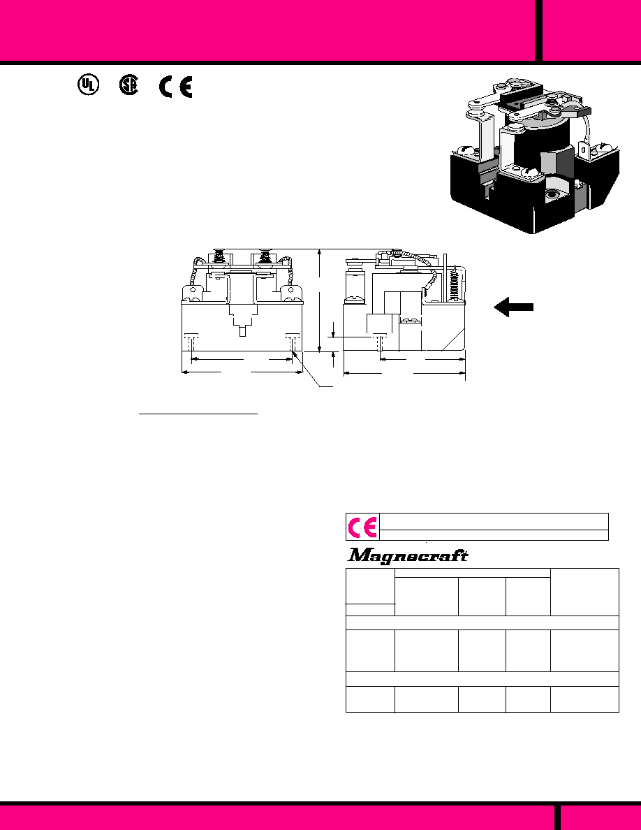
OPEN STYLE POWER RELAY
PAGE 142
WEBSITE: www.magnecraft.com EMAIL:info@magnecraft.com FAX ON DEMAND 1-800/891-2957, DOCUMENT 100
C L A S S
199
DC OPERATED (DPST-NO)
AC OPERATED (DPST-NO)
PART
NUMBERS
W199AX-8
W199AX-9
W199AX-10
W199X-7
W199X-8
DPST-NO
NOMINAL
RESIS-
TANCE
(OHMS)
NOMINAL
INPUT
VOLTAGE
NOMINAL
POWER
COIL
10 VA
10 VA
10 VA
2.0 W
2.0 W
CROSS
REFERENCE
POTTER &
BRUMFIELD
-
-
-
70
290
24 VAC
120 VAC
240 VAC, 60 Hz
220 VAC, 50 Hz
12 VDC
24 VDC
PRD7AGO-24
PRD7AGO-120
PRD7AGO-240
PRD7DGO-12
PRD7DGO-24
PART NUMBERS SHOWN ALSO AVAILABLE THRU STOCKING DISTRIBUTION.
Measured @ 25�C
AC-1, AC-3, DC-1, AC-15
*
RELEVANT IEC CONTACT UTILIZATION CATEGORIES
SPECIFICATIONS CLASS 199
80% DC Coils, 85% AC coils of
nominal voltage or Less @ 25�C
10% of Nominal Voltage or More @ 25�C
�
10% Measured @ 25�C
DC Coils-4 Watts Max. Continuous.
DPST-NO
Each pole rated 30 Amps up to 300 VAC,
50/60Hz, 5 Amps @ 480/600VAC , 0.75pF
Inductive load. 1-1/2 HP Motor Load (each
Pole) @ 120 thru 600 VAC, 50/60 Hz. 2 HP
Motor Load @ 200 thru 600 VAC, 50/60
Hz only when using two pole to switch both
sides of Load 30 Amps @ 28 VDC Resistive
load each Pole.
NEMA A600 Pilot Duty 50/60Hz
Silver Cadmium Oxide, Gold Flashed.
5/16" Diameter Standard.
40 Milliseconds Max. @ Nominal V
35 Milliseconds Max. @ Nominal V
1500 V rms
2200 V rms
(AC) -30�C to +50�C, (DC) -30�C +60�C
-30�C to +100�C
100,000 Operations
5,000,000 Operations
6-32 Binder Head Screws
8-32 Binder Head Screws
Molded Phenolic, UL Recognized
(QMFZ2)
9 oz. - 255 Grams approx... (DPST-NO)
COIL
Pull-in Voltage:
Dropout Voltage:
Coil Resistance:
Max. Coil Dissipation:
CONTACTS
Contact Combinations:
Contact Rating each Pole:
Contact Material:
TIMING
Operate time
Release Time:
DIELECTRIC STRENGTH
Between Open Contacts:
Mutually Insulated
Conductive elements:
TEMPERATURE
Operating Range:
Non-Operating Storage
range:
LIFE
Electrical (Rated Load):
Mechanical (No Load):
MISCELLANEOUS
Coil Terminals:
Contact Terminals:
Base Material:
Weight:
CLASS 199 DPST-NO
1-1/2 HP PER POLE
2 Hp - 2 POLE SWITCHING
CLASS "B" COIL
INSULATION SYSTEM
1.62
41.14
2.50
(63.5)
1.87
(47.5
0.187 Dia.
(2 Places)
2.43 Max.
(61.7)
.375
(9.5)
2.25 Max.
(57.15)
OUTLINE DIMENSIONS
Dimensions shown in Inch & (Millimeters)
UP
VERTICAL MOUNTING
RECOMMENDED WITH
CONTACTS UP
COMPLIES WITH
REQUIREMENTS OF
IEC STANDARDS
947-4-1 AND 947-5-1
LOW VOLTAGE DIRECTIVE
IEC = INTERNATIONAL
ELECTROTECHNICAL COMMISSION
*
*
UL Listed
File No. E43641
AUXILIARY CONTACTS AND OTHER COIL VOLTAGES ARE
AVAILABLE ON SPECIAL ORDER. CONTACT FACTORY FOR
SPECIAL REQUIREMENTS.
SEE SECTION 11, FOR RELEVANT UTILIZATION CATEGORIES
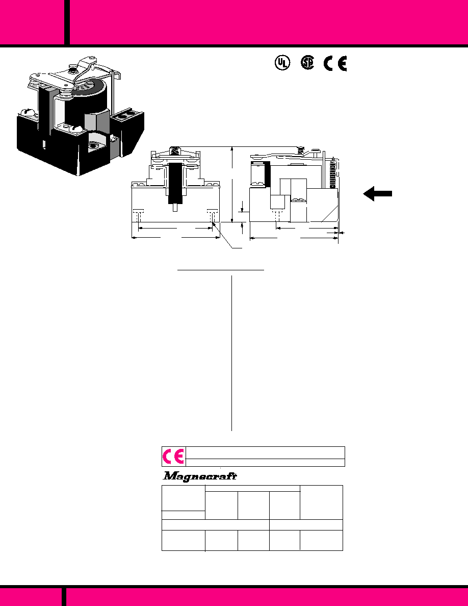
OPEN STYLE POWER RELAY
C L A SS
199
PAGE 143
2.50
(63.5)
1.87
(47.5)
MAGNETIC
Blowout
2.18 Max.
(55.4)
.375
(9.5)
0.10
(2.54)
1.62
41.14
2.43 Max.
(61.7)
0.187 Dia.
(2 Places)
OUTLINE DIMENSIONS
Dimensions shown in Inch & (Millimeters)
UP
VERTICAL MOUNTING
RECOMMENDED WITH
CONTACTS UP
CLASS 199DB
SPST-NO-DM WITH
MAGNETIC BLOWOUT
FOR DC ARC QUENCING
COMPLIES WITH
REQUIREMENTS OF
IEC STANDARDS
947-4-1 AND 947-5-1
LOW VOLTAGE DIRECTIVE
IEC = INTERNATIONAL
ELECTROTECHNICAL COMMISSION
*
*
UL Listed
File No. E43641
SPECIFICATIONS CLASS 199
TIMING
Operate time:
Release Time:
DIELECTRIC STRENGTH
Between Open Contacts:
Mutually Insulated
Conductive elements:
TEMPERATURE
Operating Range:
Non-Operating Storage
range:
LIFE
Electrical (Rated Load):
Mechanical (No Load):
MISCELLANEOUS
Coil Terminals:
Contact Terminals:
Base Material:
Weight:
COIL
Pull-in Voltage:
Dropout Voltage:
Coil Resistance:
Max. Coil Dissipation:
CONTACTS
Contact Combinations:
Contact Rating :
Additional Ratings, with
Blowout Magnet for DC
switching:
Contact Material:
80% DC Coils, 85% AC coils of
nominal voltage or Less @ 25�C
10% of Nominal Voltage or More @ 25�C
�
10% Measured @ 25�C
DC Coils-4 Watts Max. Continuous.
SPST-NO-DM Double Make
30 Amps up to 300 VAC, 50/60Hz, 5 Amps
@ 480/600Vac, 0.75pF Inductive Load.
1-1/2 HP Motor Load (each Pole) @ 120 thru
600 VAC, 50/60 Hz.
2 HP Motor Load @ 200 thru 600 VAC, 50/60 Hz
only when using two poles to switch .
30 Amps @ 28 VDC Resistive Each Pole.
NEMA A600 Pilot Duty 50/60Hz
20 Amps @ 110 VDC, Resistive; 8 Amps at 220 VDC,
Resistive, 4 Amps @ 325 VDC Resistive. 2 amps @
500 VDC resistive. For Inductive Loads, contacts
must be derated accordingly. Capacitive loads must
be limited to insure that inrush current will not exceed
100 Amps.
Silver Cadmium Oxide, Gold Flashed.
5/16" Diameter Standard.
40 Milliseconds Max. @ Nominal V
30 Milliseconds Max. @ Nominal V
1500 V rms
2200 V rms
(AC) -30�C to +50�C, (DC) -30�C +60�C
-30�C to +100�C
100,000 Operations
5,000,000 Operations
6-32 Binder Head Screws
8-32 Binder Head Screws
Molded Phenolic, UL Recognized (QMFZ2)
8 oz. - 227 Grams approx. (SPST-NO-DM)
WEBSITE: www.magnecraft.com EMAIL:info@magnecraft.com FAX ON DEMAND 1-800/891-2957, DOCUMENT 100
AC-1, AC-3, DC-1, AC-15
*
RELEVANT IEC CONTACT UTILIZATION CATEGORIES
PART NUMBERS SHOWN ALSO AVAILABLE THRU STOCKING DISTRIBUTION.
AC OPERATED (SPST-NO-DM WITH MAGNETIC BLOWOUT)
W199ADBX-4
PART
NUMBER
NOMINAL
INPUT
VOLTAGE
120 VAC
NOMINAL
RESIS-
TANCE
(OHMS)
-
NOMINAL
POWER
CROSS
REFERENCE
POTTER &
BRUMFIELD
10 VA
PRD3AJ0-120
COIL Measured @ 25�C
AUXILIARY CONTACTS AND OTHER COIL VOLTAGES ARE
AVAILABLE ON SPECIAL ORDER. CONTACT FACTORY FOR
SPECIAL REQUIREMENTS.
SEE SECTION 11, FOR RELEVANT UTILIZATION CATEGORIES

DOUBLE MAKE OR BREAK POWER RELAYS
C L A S S
199
PAGE 144
WEBSITE: www.magnecraft.com EMAIL:info@magnecraft.com FAX ON DEMAND 1-800/891-2957, DOCUMENT 100
*
RELEVANT IEC CONTACT UTILIZATION CATEGORIES
PART NUMBERS SHOWN ALSO AVAILABLE THRU STOCKING DISTRIBUTION.
DC OPERATED (SPST-NC-DB WITH 30 AMP SCREW TERMINALS)
AC OPERATED (SPST-NO-DM WITH 30 AMP SCREW TERMINALS)
DC OPERATED (SPST-NO-DM WITH 30 AMP SCREW TERMINALS)
W199DYX-2
W199ADX-4
W199ADX-5
W199DX-2
W199DX-3
12 VDC
120 VAC
240 VAC, 60 Hz
220 VAC, 50 Hz
12 VDC
24 VDC
NOMINAL
INPUT
VOLTAGE
NOMINAL
RESIS-
TANCE
(OHMS)
2.0 W
10 VA
10 VA
2.0 W
2.0 W
COIL Measured @ 25�C
NOMINAL
POWER
CROSS
REFERENCE
POTTER &
BRUMFIELD
PRD4DG0-12
PRD3AG0-120
PRD3AG0-240
PRD3DG0-12
PRD3DG0-24
AC-1, AC-3, DC-1, AC-15
70
-
-
70
290
PART
NUMBERS
SPECIFICATIONS CLASS 199
COIL
Pull-in Voltage:
Dropout Voltage:
Coil Resistance:
Max. Coil Dissipation:
CONTACTS
Contact Combinations:
Contact Rating SPST-NO-DM:
:Contact Material:
TIMING
Operate time
Release Time:
DIELECTRIC STRENGTH
Between Open Contacts:
Mutually Insulated
Conductive elements:
TEMPERATURE
Operating Range:
Non-Operating Storage
range:
LIFE
Electrical (Rated Load):
Mechanical (No Load):
MISCELLANEOUS
Coil Terminals:
Contacts Terminals:
Base Material:
Weight:
80% DC Coils, 85% AC coils of
nominal voltage or Less. @ 25�C
10% of Nominal Voltage or More @ 25�C
�
10% @ 25�C
DC Coils-4 Watts Max. Continuous.
SPST-NC (Double Break
SPST-NO (Double Make
30 Amps up to 300 VAC, 50/60Hz
12 Amps @ 480, 10 Amps @ 600VAC, 50/60
0.75pF Inductive Load. 2 HP Motor Load
@ 120 thru 600 VAC, 50/60 Hz. 30 Amps
@ 28 VDC Resistive load.
NEMA A600 Pilot Duty 50/60Hz
Silver Cadmium Oxide, Gold Flashed.
5/16" Diameter Standard.
40 Milliseconds Max. @ Nominal V
30 Milliseconds Max. @ Nominal V
1500 V rms
2200 V rms
(AC) -30�C to +50�C, (DC) -30�C +60�C
-30�C to +100�C
100,000 Operations
5,000,000 Operations
6-32 Binder Head Screws
8-32 Binder Head Screws
Molded Phenolic, UL recognized
(QMz2)
8 oz. - 227 Grams approx.
1.62
41.14
2.50
(63.5)
2.43 Max.
(61.7)
.375
(9.5)
0.10
(2.54)
0.187 Dia.
(2 Places)
OUTLINE DIMENSIONS
Dimensions shown in Inch & (Millimeters)
2.25 Max.
(57.15)
1.87
(47.5)
UP
VERTICAL MOUNTING
RECOMMENDED WITH
CONTACTS UP
S P S T - N C - D B
S P S T - N O - D M
CLASS 199 SPST-NC-DB
OR SPST-NO-DM
RATED 30 AMPS @ 2 HP
CLASS "B" COIL
INSULATION SYSTEM
COMPLIES WITH
REQUIREMENTS OF
IEC STANDARDS
947-4-1 AND 947-5-1
LOW VOLTAGE DIRECTIVE
IEC = INTERNATIONAL
ELECTROTECHNICAL COMMISSION
*
*
UL Listed
File No. E43641
AUXILIARY CONTACTS AND OTHER COIL VOLTAGES ARE
AVAILABLE ON SPECIAL ORDER. CONTACT FACTORY FOR
SPECIAL REQUIREMENTS.
SEE SECTION 11, FOR RELEVANT UTILIZATION CATEGORIES
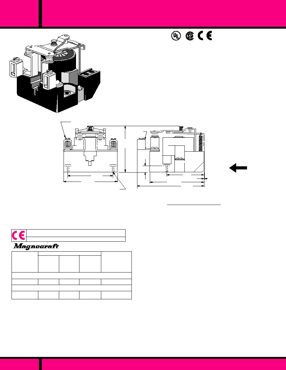
DOUBLE MAKE POWER RELAYS
199
C L A S S
PAGE 145
WEBSITE: www.magnecraft.com EMAIL:info@magnecraft.com FAX ON DEMAND 1-800/891-2957, DOCUMENT 100
AC OPERATED (SPST-NO-DM WITH 50 AMP BOX TERMINALS)
DC OPERATED (SPST-NO-DM WITH 50 AMP BOX TERMINALS)
PART NUMBERS SHOWN ALSO AVAILABLE THRU STOCKING DISTRIBUTION.
W199ADEX-4
W199DEX-3
NOMINAL
INPUT
VOLTAGE
120 VAC
24 VDC
NOMINAL
RESIS-
TANCE
(OHMS)
-
290
COIL Measured @ 25�C
NOMINAL
POWER
CROSS
REFERENCE
POTTER &
BRUMFIELD
10 VA
2.0 W
PART
NUMBERS
PRD3AP4-120
PRD3DP4-24
AC-1, AC-3, DC-1, AC-15
*
RELEVANT IEC CONTACT UTILIZATION CATEGORIES
SPECIFICATIONS CLASS 199
80% DC Coils, 85% AC coils of
nominal voltage or Less. @ 25�C
10% of Nominal Voltage or More @ 25�C
�
10% @ 25�C
DC Coils-4 Watts Max. Continuous.
SPST-NO Double Make
50 Amps up to 300 VAC, 50/60Hz
50 Amps @ 28 VDC Resistive load. Loads
must be current limited as not to exceed
100 Amp inrush Currents.
NEMA A600 Pilot Duty 50/60Hz
Silver Cadmium Oxide, Gold Flashed.
5/16" Diameter Standard.
40 Milliseconds Max. @ Nominal V
30 Milliseconds Max. @ Nominal V
1500 V rms
2200 V rms
(AC) -30�C to +50�C, (DC) -30�C +60�C
-30�C to +100�C
100,000 Operations
5,000,000 Operations
6-32 Binder Head Screws
8-32 Binder Head Screws
Molded Phenolic, UL Recognized
(QMFZ2)
8 oz. - 227 Grams approx.
COIL
Pull-in Voltage:
Dropout Voltage:
Coil Resistance:
Max. Coil Dissipation:
CONTACTS
Contact Combinations:
Contact Ratings :
Contact Material:
TIMING
Operate time
Release Time:
DIELECTRIC STRENGTH
Between Open Contacts:
Mutually Insulated
Conductive elements:
TEMPERATURE
Operating Range:
Non-Operating Storage
range:
LIFE
Electrical (Rated Load):
Mechanical (No Load):
MISCELLANEOUS
Coil Terminals:
Contacts Terminals:
Base Material:
Weight:
CLASS 199 SPST-NO-DM
RATED 50 AMPS - 2HP
WITH BOX TERMINALS.
CLASS "B" COIL
INSULATION SYSTEM
COMPLIES WITH
REQUIREMENTS OF
IEC STANDARDS
947-4-1 AND 947-5-1
LOW VOLTAGE DIRECTIVE
IEC = INTERNATIONAL
ELECTROTECHNICAL COMMISSION
*
*
UL Listed
File No. E43641
0.10
(2.54)
.375
(9.5)
2.50
(63.5)
1.87
(47.5)
2.18 Max.
(55.4)
Box
Terminal's
0.187 Dia.
(2 Places)
3.50 Max.
(88.9)
2.43 Max.
(61.7)
1.62
41.14
50 AMP BOX TERMINALS ACCEPT
NO.14 THRU NO. 6 AWG. WIRE
UP
VERTICAL MOUNTING
RECOMMENDED WITH
CONTACTS UP
OUTLINE DIMENSIONS
Dimensions shown in Inch & (Millimeters)
SHOWN WITH
BOX TERMINALS
AUXILIARY CONTACTS AND OTHER COIL VOLTAGES ARE
AVAILABLE ON SPECIAL ORDER. CONTACT FACTORY FOR
SPECIAL REQUIREMENTS.
SEE SECTION 11, FOR RELEVANT UTILIZATION CATEGORIES

DC SWITCHING POWER RELAY
199
PAGE 146
WEBSITE: www.magnecraft.com EMAIL:info@magnecraft.com FAX ON DEMAND 1-800/891-2957, DOCUMENT 100
C L A S S
CLASS 199B
DPDT WITH MAGNETIC
BLOWOUT FOR DC ARC
QUENCHING
10 AMP @ 110 VDC
CLASS "B" COIL
INSULATION SYSTEM
UL Listed
File No. E43641
*
RELEVANT IEC CONTACT UTILIZATION CATEGORIES
AC OPERATED (DPDT WITH BLOW OUT MAGNET)
DC OPERATED (DPDT WITH BLOW OUT MAGNET)
PART NUMBERS SHOWN ALSO AVAILABLE THRU STOCKING DISTRIBUTION.
W199ABX-14
W199BX-14
PART
NUMBERS
COIL Measured @ 25�C
120 VAC
110 VDC
-
6000
10 VA
2.0 W
PRD11AJ0-120
PRD11DJ0-110
CROSS
REFERENCE
POTTER &
BRUMFIELD
NOMINAL
POWER
NOMINAL
RESIS-
TANCE
(OHMS)
NOMINAL
INPUT
VOLTAGE
AC-1, AC-3, DC-1, AC-15
0.187 Dia.
(2 Places)
MAGNETIC BLOW OUT
MAGNETIC BLOW OUT
OUTLINE DIMENSIONS
Dimensions shown in Inch & (Millimeters)
2.50
(63.5)
1.87
(47.5
.375
(9.5)
1.62
(41.14)
2.53 Max.
(64.3)
3.12
(79.24
UP
VERTICAL MOUNTING
RECOMMENDED WITH
CONTACTS UP
80% DC Coils, 85% AC coils of
nominal voltage or Less @ 25�C
10% of Nominal Voltage or More TM 25�C
�
10% @ 25�C
DC Coils-4 Watts Max. Continuous.
DPDT
30 Amps up to 300 VAC, 50/60Hz
5 Amps @ 480/600VAC , 0.75pF Inductive
Load. 1-1/2 HP Motor Load (each Pole)
@ 120 thru 600 VAC, 50/60 Hz. 2 HP
Motor Load @ 200 thru 600 VAC, 50/60
Hz only when using two poles to switch both
sides of Load 30 Amps @ 28 VDC Resistive
Each Pole.
NEMA A600 Pilot Duty 50/60 Hz
10 Amps @ 110 VDC, Resistive; 4 Amps
at 220 VDC, Resistive, 2 Amps @ 325VDC
Resistive. For inductive Loads, contacts
must be derated accordingly. Capacitive
loads must have current limiting to insure
that inrush current will not exceed 50 Amps
Silver Cadmium Oxide, Gold Flashed.
5/16" Diameter Standard.
40 Milliseconds Max. @ Nominal V
30 Milliseconds Max. @ Nominal V
1500 V rms
2200 V rms
(AC) -30�C to +50�C, (DC) -30�C +60�C
-30�C to +100�C
100,000 Operations
5,000,000 Operations
6-32 Binder Head Screws
8-32 Binder Head Screws
Molded Phenolic, UL Recognized
(QMFZ2)
11 oz. - 312 Grams approx.. (DPDT)
SPECIFICATIONS CLASS 199
COIL
Pull-in Voltage:
Dropout Voltage:
Coil Resistance:
Max. Coil Dissipation:
CONTACTS
Contact Combinations:
Contact Rating :
DC Ratings:
Contact Material:
TIMING
Operate time:
Release Time:
DIELECTRIC STRENGTH
Between Open Contacts:
Mutually Insulated
Conductive elements:
TEMPERATURE
Operating Range:
Non-Operating Storage
range:
LIFE
Electrical (Rated Load)
Mechanical (No Load)
MISCELLANEOUS
Coil Terminals:
Contact Terminals:
Base Material
Weight:
*
*
COMPLIES WITH
REQUIREMENTS OF
IEC STANDARDS
947-4-1 AND 947-5-1
LOW VOLTAGE DIRECTIVE
IEC = INTERNATIONAL
ELECTROTECHNICAL COMMISSION
AUXILIARY CONTACTS AND OTHER COIL VOLTAGES ARE
AVAILABLE ON SPECIAL ORDER. CONTACT FACTORY FOR
SPECIAL REQUIREMENTS.
SEE SECTION 11, FOR RELEVANT UTILIZATION CATEGORIES
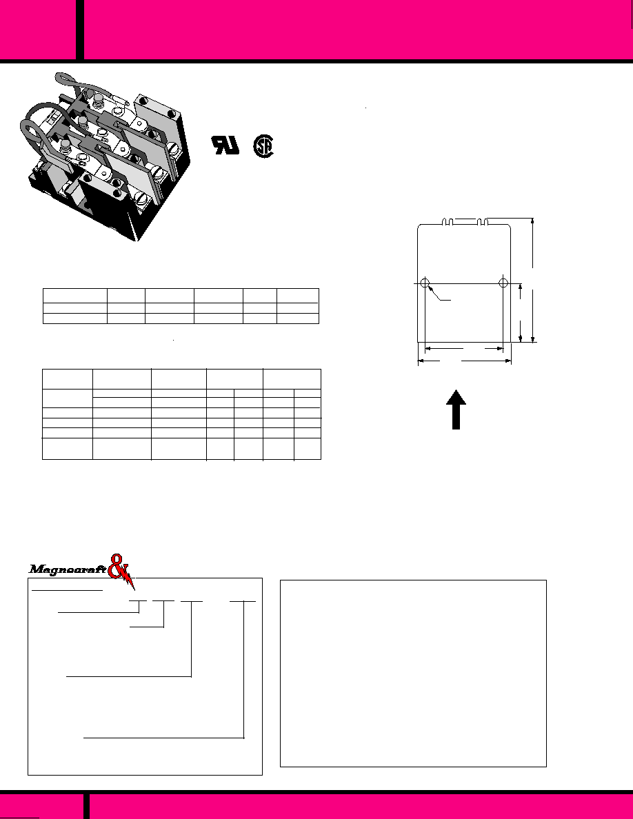
SERIES
425
PAGE 147
WEBSITE: www.magnecraft.com EMAIL:info@magnecraft.com FAX ON DEMAND 1-800/891-2957, DOCUMENT 100
OPEN STYLE - 3 POLE, 30 AMP POWER RELAY
The series 425 Power relay is capable of handling up to 30 Amps and
1 Hp Loads. The Series 425 has sufficient spacing to allow for 600
Vac contact ratings . The Design features a enclosed coil, Screw
Terminals and Silver Cadmium Oxide contacts as standard.
The Series 425 has a wide choice of options to choose from.
CONTACTS
Contact Material:
TIMING
Operate Time:
Release Time:
INSULATION CHARACTERISTICS
Dielectric Strength
Insulation Resistance:
ENVIRONMENTAL CAPABILITIES
Ambient Temperature Rating:
LIFE EXPECTANCY
Mechanical:
Electrical:
MISCELLANEOUS
Enclosure:
Weight:
ULRecognized
File No. E13224
GENERAL SPECIFICATIONS
Silver Cadmium Oxide.
30 mS Max. @ Nominal Voltage.
15 mS Max. @ Nominal Voltage.
2500 V rms between Mutually insulated
current carrying parts and those parts to
ground.
500 VDC Exceeds 1000 Megohms.
AC: -55�C to +45�C @ Rated Operation.
DC: -55�C to +80 �C
10 Million Operations no load
100,000 Operations @ Rated Load.
Open Style
Small Base 9oz. large base 11 oz.approx.
ORDERING CODE
Typical Type No.
425 XCX -120A
Series
425 Screw Terminal, 30A, 1-3 Pole
Contact Arrangements
Insulated Armature Types (600V)
CXX 3PST-NO
XCX 3PDT
Options
Tungsten Contacts (High Inrush) - CODE W
0.25 inch quick connect terminals- CODE 18
1 Aux. Contact (SPDT Snap Switch, 10A ) - CODE 90
2 Aux. Contact (SPDT Snap Switches, 10A ) - CODE 91
Coil Voltage
AC: 6, 12, 24, 48, 120, 240, 480 (Add "A")
DC: 6, 12, 24, 48, 110 -125 (Add "D")
Struthers-Dunn
Dimensions shown are in INCHES and (millimeters)
VERTICAL MOUNTING
RECOMMENDED WITH
CONTACTS UP
UP
OUTLINE DIMENSIONS
3.24
(82.3)
1.675
(42.5)
2.50
(63.5)
1.875
(47.6)
0.20 Dia.Typ.
Current (MA)
12
24
48
120 *
240 **
480
1.8
6.7
27
170
680
2720
1600
820
410
85
43
22
333
169
84
18-21
-
-
11VA
11VA
11VA
11VA
11VA
11VA
AC
DC
AC
DC
AC
DC
35.5
142
568
2980
-
-
4.0W
4.0W
4.0W
4.0W
Power
Consumption
Nominal
Voltage
Resistance
Ohms
�
10%
Resistance
Ohms
�
10%
COIL SPECIFICATIONS 3 POLE RELAYS @ 25�C
1, 2, and 3 Pole Relays
Min. Operate:
AC: 85% of nominal Voltage or less @ 25�C
DC: 75% of nominal Voltage or less @ 25�C
Max. Over Voltage: 110% of nominal
* AC Coil is 120V, 50/60Hz, DC Coil is 110-125VD
** For 220 VDC use 3600
, 10 Watt resistor in series with 110 VDC relay.
120-240/AC
600/AC
277/AC
208-240/AC
25A
25A
17A
10A
PER POLE
1� 1HP
3� 3HP
-
-
Load
General Duty
Motor (45% PF)
30/DC
30A
1� 1HP
CONTACT LOAD RATINGS 3 POLE RELAYS
3PDT

OPEN STYLE 30 AMP POWER RELAY
PART NUMBER SHOWN ALSO AVAILABLE THRU STOCKING DISTRIBUTION
PAGE 148
WEBSITE: www.magnecraft.com EMAIL:info@magnecraft.com FAX ON DEMAND 1-800/891-2957, DOCUMENT 100
1.937.
(49.1)
.078
(1.98)
.437
(11.1)
.062
(1.57)
.250
(6.35)
.156
(3.9)
1.25Max.
(31.7)
1.406
(35.7)
6-32 tapped mt.
hole x .312
d e e p
CLASS 88UKD RELAY
SIDE COIL SOLDER TERMINALS
SPST-N.O. DM, RATED 30 AMPS
1/4"QUICK CONNECT /SOLDER TERMINALS
SWITCHES UP TO 1 HP AT 600 VAC
UL Recognized
File No. E43641
-10�C to +50�C @ Rated Operation. (AC )
-10�C to +60�C @ Rated Operation. (DC )
5g's 10 to 55Hz.
5g's 11mS Max.
5 Million Operations
100,000 Operations @ Rated Load.
Movable & stationary contacts are mounted
on a molded plastic barrier insulator.
Open style construction.
6-32 tapped hole and locating tab.
85 Grams, 3 oz. approx.
COIL
Pull-in Voltage (AC):
Pull-in Voltage (DC):
Dropout Voltage:
Max. allowed voltage
Coil Resistance:
CONTACTS
Contact Material:
Contact Resistance:
Contact Rating:
TIMING
Operate Time:
Release Time:
DIELECTRIC STRENGTH
Contacts to coil:
Across open contacts:
Contacts to frame:
Insulation Resistance:
85% of Nominal Voltage or less
80% of Nominal Voltage or less
10% of nominal voltage or more
110% of nominal voltage
�
10% Measured @ 25�C
1/4' silver alloy, gold flashed.
Initial 50 Milliohms @ rated current.
30 Amps up to 300VAC/28VDC,
Resistive Load
5 Amps @ 600VAC Resistive.Load
1 HP @ 120-600 VAC Motor load.
25 mS Max. @ Nominal Voltage.
20 mS Max. @ Nominal Voltage
3000 V rms
1000 V rms
3000 V rms
1000
megohms min. @ 500 VDC
TEMPERATURE
Operating:
VIBRATION RESISTANCE
Functional:
SHOCK RESISTANCE
Functional:
LIFE EXPECTANCY
Mechanical:
Electrical:
MISCELLANEOUS
Contact Insulation:
Style:
Mounting:
Weight:
SPECIFICATIONS 88UKD
KR-3AH-24
KR-3AH-120
KR-3AH-240
KR-3DH-12
KR-3DH-24
KR-3DH-110
W88UKADX-3
W88UKADX-4
W88UKADX-5
W88UKDX-2
W88UKDX-3
W88UKDX-4
DC OPERATED COIL
AC OPERATED COIL
24VAC
120VAC
240VAC,60Hz
220VAC,50Hz
12 VDC
24 VDC
110 VDC
NOMINAL
INPUT
VOLTAGE
NOMINAL
RESISTANCE
(OHMS)
-
-
-
100
400
8000
Coil Measured @ 25�C
PART
NUMBERS
3VA
3VA
3VA
1.5W
1.5W
1.5W
NOMINAL
POWER
CROSS REFERENCE
TO
POTTER & BRUMFIELD
PART NUMBERS SHOWN ALSO AVAILABLE THRU STOCKING DISTRIBUTION.
88UKD
C L A S S

SERIES
415
SCREW TERMINAL 15 AMP, 1 AND 2 POLE POWER RELAY
PAGE 149
WEBSITE: www.magnecraft.com EMAIL:info@magnecraft.com FAX ON DEMAND 1-800/891-2957, DOCUMENT 100
415 XBX 18 -120A
ORDERING CODE
Typical Type No.
Series
415 Screw Terminals, 15 Amp
1 and 2 pole
Contact Arrangements
BXX (DPST-NO.
HXX (SPST-NO-DM
XAX (SPDT)
XBX (DPDT)
XHX (SPDT-DB-DM
XXH (SPST-NC-DB
Options
0.25 inch quick connect terminals - CODE 18
Permanent Magnet Blowout - CODE 69
(Consult Factory for other options)
Coil Voltage
AC: 6, 12, 24, 48, 120, 240, (Add "A")
DC: 6, 12, 24, 32, 48, 115-125 (Add "D")
4 mtg.holes
0.181
�
.005 Dia.
1.50
(38.1)
1.87
(47.4)
2.35
(59.69)
2.75
(69.85)
Listed (XBX Only)
R
file No. E13224
Struthers-Dunn
UP
VERTICAL MOUNTING
RECOMMENDED WITH
CONTACTS UP
OUTLINE DIMENSIONS
Dimensions shown in Inch and (Millimeters)
The Series 415 is a compact, 15 amp base mounted industrial relay. It is a versatile
relay that offers a variety of contact configurations and options. Excellent contact life
assures long mechanical life and contact reliability on low level loads. Screw
terminals are standard. Options include: high voltage or high inrush contacts, quick
connect terminals, permanent magnet blowout and low power DC coils.
415XBX
415HXX
415XXH
415XHX
415BXX
415XAX
WIRING DIAGRAMS
TOP VIEW
MAXIMUM DEPTH DIMENSION OF CONTACTOR 1.75",
(44.45)
Special coils: Low Power (mW), series coils.
High Inrush contacts: 10 Amps continuous, 150 Amp Inrush.
High Voltage Contacts: Up to 4KV

SERIES
415
SCREW TERMINAL 15 AMP, 1 AND 2 POLE POWER RELAY
PART NUMBER SHOWN ALSO AVAILABLE THRU STOCKING DISTRIBUTION
PAGE 150
WEBSITE: www.magnecraft.com EMAIL:info@magnecraft.com FAX ON DEMAND 1-800/891-2957, DOCUMENT 100
105-1420
105-3420
105-4420
105-6420
105-1421
105-3421
105-4421
105-6421
105-1422
105-3422
105-4422
105-6422
105-1520
105-3520
105-4520
105-6520
105-1521
105-3521
105-4521
105-6521
105-7521
105-1522
105-3522
105-4522
105-6522
105-7522
CROSS REFERENCE
STRUTHERS-DUNN TO WARD LEONARD
415BXX-6D
415BXX-12D
415BXX-24D
415BXX-110D
415XXB-6D
415XXB-12D
415XXB-24D
415XXB-110D
415XBX-6D
415XBX-12D
415XBX-24D
415XBX-110D
415BXX-6A
415BXX-12A
415BXX-24A
415BXX-120A
415XXB-6A
415XXB-12A
415XXB-24A
415XXB-120A
415XXB-240A
415XBX-6A
415XBX-12A
415XBX-24A
415XBX-120A
415XBX-240A
DC COIL 2 POLE N.O.
DC COIL DPDT
AC COIL 2 POLE N.O..
AC COIL 2 POLE N.C..
AC COIL DPDT
DC COIL 2 POLE N.C..
STRUTHERS-DUNN WARD LEONARD
NOTE:
THE 105 STYLE IS SLIGHTLY SMALLER WITH
A DIFFERENT MOUNTING HOLE PATTERN.
Resistance
Ohms
�
10%
Nominal Voltage
(60HZ)
1.5
6.3
25
100
620
2500
1000
500
250
125
50
25
1800
900
450
225
90
45
6
12
24
48
120
240
Inrush
Current
Sealed
Coil
AC COIL SPECIFICATIONS @ 25�C (6VA)
mA @ nominal voltage
C O I L
Pull-in Voltage:
Dropout Voltage:
Max. allowed voltage:
Coil Resistance:
C O N T A C T S
Contact Material:
TIMING
Operate Time:
Release Time:
DIELECTRIC STRENGTH
All Mutually Insulated Points:
Insulation Resistance:
T E M P E R A T U R E
Temperature Rating:
LIFE EXPECTANCY
Mechanical:
Electrical:
M I S C E L L A N E O U S
Weight:
80% of nominal voltage or less measured
at 25�C
10% of nominal voltage or more @ 25�C
110% of nominal voltage
�
10% Measured @ 25�C
Silver Cadmium Oxide.
25 mS Max. @ Nominal Voltage.
10mS Max. @ Nominal Voltage.
1500 V rms between all mutually
Insulated current carrying parts and
those parts to ground.
500 VDC Exceeds 1000 Megohms.
AC: -45�C to +55�C @ rated operation.
DC: -45�C to +70�C @ rated operation
20 Million Operations no load
200,000 Operations @ Rated Load.
500,000 Operations @ 1/2 rated load.
4 oz. (113 g) approx.
GENERAL SPECIFICATIONS
Resistance
Ohms
�
10%
10
40
155
390
620
4000
500
250
125
95
62
26
600
300
150
112
75
31
6
12
24
32
48
*115/125
Coils
Cold
Coils
Hot
DC COIL SPECIFICATIONS @ 25�C (3.5W)
mA @ nominal voltage
Nominal Voltage
(VDC)
* 220-250 VDC relays supplied with resistor in series
with 115/125 VDC coil.
10A
1HP
RESISTIVE MOTOR
(80% pF)
15A
-
15A
1/2HP
120VAC
30/VDC
LOAD
240VAC
CONTACT RATINGS

SERIES
A275
MOTOR REVERSING CONTACTOR, 1 & 3 HP, 6 POLE
UL Recognized
File No. E13224B
The Series A275 relay is a 2 coil, compact motor reversing contactor which finds
extensive applications in the Industrial door operator Industry, the hoist Industry and
electronic wheel balancers, to name a few. The A275 has Q.C. coil terminals
extending out the back (opposite the contact terminals), mechanically interlocked
armatures is a standard feature.
.187 (4.76)
2 holes for
#8 screws
3.37
(85.6)
3.62
(91.9)
2.31
(58.9)
2.75
(69.8)
2.985
(75.81 2.56
(65.0)
A
U
X
1.59
(40.3)
OUTLINE DIMENSIONS
Dimensions shown in Inch and (Millimeters)
2
1
3
4
5
6
7
8
9
Auxiliary contact
Snap Switches
TOP VIEW
Main contact terminals are
numbered on contactor
WIRING DIAGRAM
OPTIONS (CONSULT FACTORY)
ORDERING CODE
Typical Type No.
Series
A275, 1/4" Terminals, motor reversing.
Continuous , 1 & 2 Hp, 3 pole models
Contact Arrangements
KXX (3PDM-NO., per coil)
Options
2 Aux. contacts, each SPDT
(1 per coil) 1/4" Q.C. terminals - CODE 90
4 Aux. contacts, each SPDT
(2 per coil) 1/4" Q.C. terminals - CODE 91
Rectified Coil - CODE V2
Coil Voltage
AC: 12, 24, 110, 120, 220, 240 (Add "A")
DC: 12, 24, 32, 48, 120 (Add "D")
A275 KXX 90 -24A
Struthers-Dunn
UP
RECOMMENDED
MOUNTING POSITION
PAGE 151
WEBSITE: www.magnecraft.com EMAIL:info@magnecraft.com FAX ON DEMAND 1-800/891-2957, DOCUMENT 100
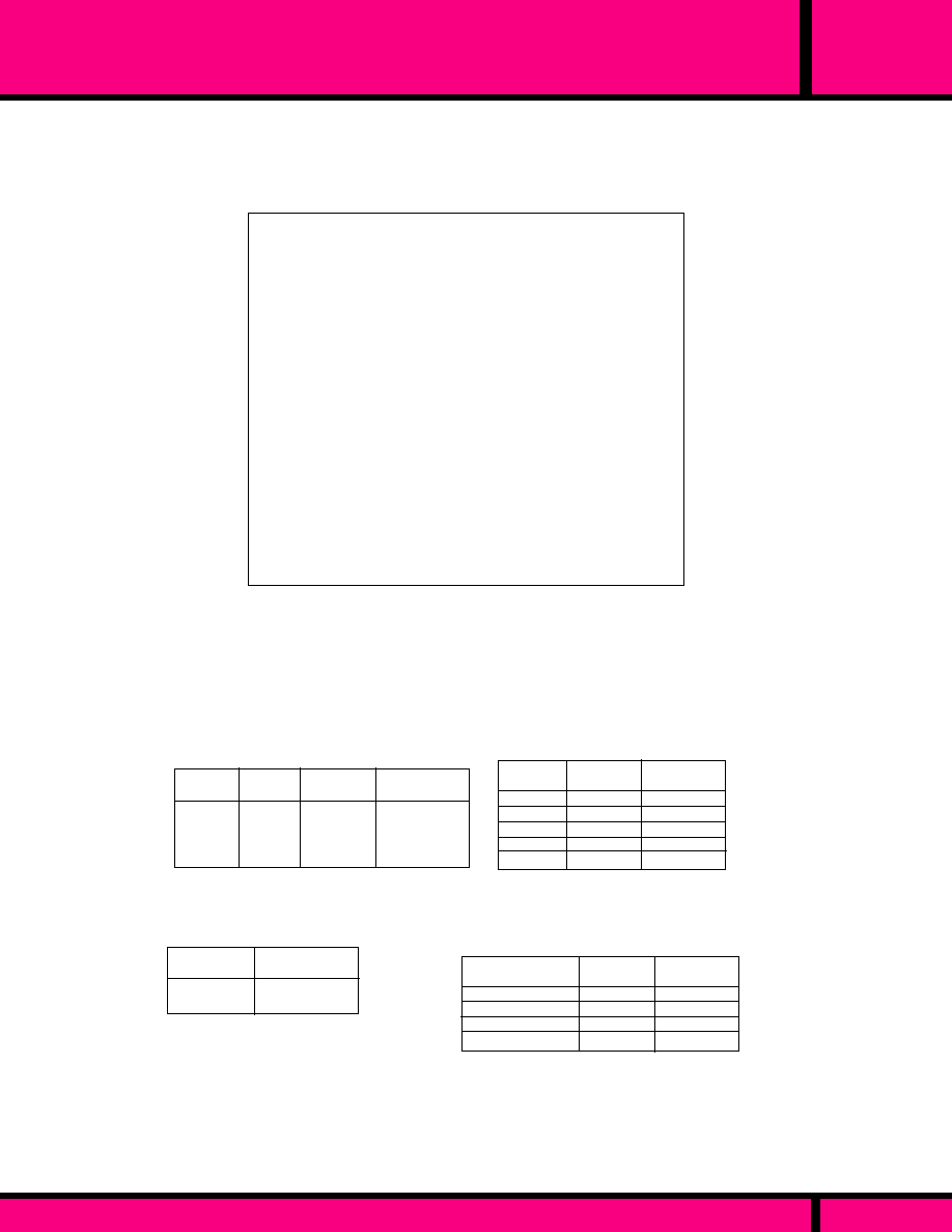
C O I L
Pull-in Voltage:
Dropout Voltage:
Max. allowed voltage:
Coil Resistance:
C O N T A C T S
Contact Material:
TIMING
Operate Time:
Release Time:
DIELECTRIC STRENGTH
All Mutually Insulated Points:
Insulation Resistance:
T E M P E R A T U R E
Temperature Rating:
LIFE EXPECTANCY
Mechanical:
Electrical:
M I S C E L L A N E O U S
Weight:
AC: 85%, DC: 80% of nominal voltage
measured at 25�C
10% of nominal voltage or more @ 25�C
110% of nominal voltage
�
10% Measured @ 25�C
Silver Cadmium Oxide.
50 mS Max. @ Nominal Voltage.
30 mS Max. @ Nominal Voltage.
2500 V rms between all mutually
Insulated current carrying parts and
those parts to ground.
500 VDC Exceeds 1000 Megohms.
AC: -45�C to +50�C @ rated operation.
DC: -45�C to +70 �C @ rated operation.
5 Million Operations no load
100,000 Operations @ Rated Load.
500,000 Operations @ 1/2 rated load.
1 pound, approx..
Resistance
Ohms
�
10%
4.5W
4.6W
4.9W
4.6W
4.4W
Power
Consumption
31.0
125
210
500
3240
Nominal
Voltage
12
24
32
48
120
Polypropylene encapsulated coils
PHASE
MOTOR
LOADS (HP)
RESISTIVE
LOAD (AMPS)
1 - 2 - 3
1
2 - 3
2 - 3
15
10
10
5
1
1.5
3
3
VOLTAGE
(60HZ)
120
240
240
480/600
Resistance
Ohms
�
10%
Nominal
Voltage
17VA
16.7VA
16.8VA
16.8VA
12V/50-60hz
24V/50-60hz
110V/50-120V/60hz
220V/50-240V/60hz
1.24
4.63
125
500
Power
Consumption
VOLTAGE
(DC)
30
125
RESISTIVE
LOAD (AMPS)
15
5
DC CONTACTS
600 volt spacing to ground.
300 volt spacing for auxiliary contacts.
CONTACT RATINGS
AC CONTACTS: Rated with all contacts in use, not rated per pole.
DC COIL SPECIFICATIONS @ 25�C
AC COIL SPECIFICATIONS @ 25�C
A275
SERIES
MOTOR REVERSING CONTACTOR, 1 & 3 HP, 6 POLE
WEBSITE: www.magnecraft.com EMAIL:info@magnecraft.com FAX ON DEMAND 1-800/891-2957, DOCUMENT 100
PAGE 152
GENERAL SPECIFICATIONS
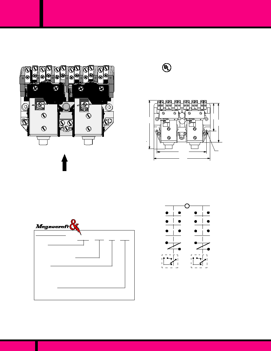
PART NUMBER SHOWN ALSO AVAILABLE THRU STOCKING DISTRIBUTION
A575
SERIES
2 COIL MOTOR REVERSING CONTACTOR 1.5 - 7.5HP, 6 POLE
NC
COM
NO
NO
NC
COM
5.25
(132)
2.56
(65.0)
4.43
(112.5)
4.75
(120.6)
3.40
(86.3)
OUTLINE DIMENSIONS
Dimensions shown in Inch and (Millimeters)
MTG. HOLES
.196 DIA. (4.97)
2 PLACES
MAXIMUM DEPTH DIMENSION OF CONTACTOR 3.00", (76.2)
UL Recognized
File No. E13224
1
3
4
6
9
7
WIRING DIAGRAM
AUXILIARY
CONTACTS
ORDERING CODE
Typical Type No.
Series
A575, Screw Terminals, 2 coil motor
rev. contactor, 1.5 - 7.5 HP
Contact Arrangements
KXX (3PDM-NO., per coil)
Options
1 Form SPST-NO & SPST-NC Aux. contacts
per coil, Rated 5 Amps - CODE 74
SPDT Aux. contact per coil
Rated 5 Amps. - CODE 90
Coil Voltage
AC: 12, 24, 120, 240, 440, 550 (Add "A")
DC: 12, 24, 115-125, 240 (Add "D")
A575 KXX 90 -24A
Struthers-Dunn
RECOMMENDED
MOUNTING POSITION
UP
The Series A575 relay is rated to 7.5 HP. Two sets of 3 pole, double-make, N.O.
contacts are mechanically Interlocked to prevent simultaneous closure. Front
mounted auxiliary contacts are available for electrical lockup and lockout. All
versions have silver cadmium oxide contacts. The A575 motor reversing contactor
is widely used for control of overhead doors, elevators, hoists, machine tools, and
other similar devices that requires frequent jogging.
Mechanical Interlock omitted, Consult Factory
OPTIONS (CONSULT FACTORY)
PAGE 153
WEBSITE: www.magnecraft.com EMAIL:info@magnecraft.com FAX ON DEMAND 1-800/891-2957, DOCUMENT 100

PART NUMBER SHOWN ALSO AVAILABLE THRU STOCKING DISTRIBUTION
WEBSITE: www.magnecraft.com EMAIL:info@magnecraft.com FAX ON DEMAND 1-800/891-2957, DOCUMENT 100
PAGE 154
A575
SERIES
2 COIL MOTOR REVERSING CONTACTOR 1.5 - 7.5HP, 6 POLE
PHASE
MOTOR
LOADS (HP)
RESISTIVE
LOAD (AMPS)
1
1
2 - 3
2 - 3
VOLTAGE
(60HZ)
30
30
30
15
1-1/2
3
5
7-1/2
120
208/240
208/240
480/600
3PST-DM-NO
(per pole)
LOAD
CONTACT RATINGS
AUXILIARY CONTACTS
RESISTIVE
LOAD (AMPS)
5
5
120
240
VOLTAGE
(AC)
1 FORM "A"
"B" OR "C"
LOAD
C O I L
Pull-in Voltage:
Dropout Voltage:
Max. allowed voltage:
Coil Resistance:
C O N T A C T S
Contact Material:
TIMING
Operate Time:
Release Time:
DIELECTRIC STRENGTH
All Mutually Insulated Points:
Insulation Resistance:
T E M P E R A T U R E
Temperature Rating:
LIFE EXPECTANCY
Mechanical:
Electrical:
M I S C E L L A N E O U S
Weight:
AC: 85%, DC: 80% of nominal voltage
measured at 25�C
10% of nominal voltage or more @ 25�C
110% of nominal voltage
�
10% Measured @ 25�C
Silver Cadmium Oxide.
60 mS Max. @ Nominal Voltage.
30 mS Max. @ Nominal Voltage.
2500 V rms between all mutually
Insulated current carrying parts and
those parts to ground.
500 VDC Exceeds 1000 Megohms.
-40�C to +50�C @ rated operation.
5 Million Operations no load
100,000 Operations @ Rated Load.
250,000 Operations @ 1/2 rated load.
1.5 pounds, approx..
GENERAL SPECIFICATIONS
Resistance
Ohms
�
10%
Nominal
Voltage
12
24
*120
240
440
550
1.833 AMP
0.917 AMP
0.183 AMP
0.920 AMP
0.050 AMP
0.040 AMP
Nominal
Current
1.00
5.30
92.0
420
2100
3100
* AC coil is 120, 50-60HZ
AC COIL SPECIFICATIONS @ 25�C (22VA)
RESISTIVE
LOAD (AMPS)
115
230
15
2
VOLTAGE
(DC)
3PST-DM-NO
(per pole)
LOAD
DC CONTACTS
Resistance
Ohms
�
10%
Nominal
Voltage
16.5
58.2
1,450
4,200
12
24
**120
240
0.727
0.412
0.083
0.055
Nominal
Current
** DC coil is 110-125 VDC
DC COIL SPECIFICATIONS @ 25�C (10 WATT)

PART NUMBER SHOWN ALSO AVAILABLE THRU STOCKING DISTRIBUTION
SERIES
101-102-103
50,100 & 200 AMP SINGLE POLE DC CONTACTORS
The Series 101, 102 and 103 are DC solenoid-actuated, heavy duty contactors.
Each contactor has a single pole, double-make normally open contact. Contacts
are enclosed with a molded plastic cover. The series 101 is rated at 50 amps
continuous duty. The series 102 is rated 100 amps continuous and the series 103 is
rated at 200 amps continuous. Coils are rated for DC only, as standard. The powerful
magnetic structure creates very high contact pressure which results in very reliable
and low resistance contacts, making them suitable for power applications in telecom-
munications, elevator and rail mass transit as well as other Industries.
ORDERING CODE
Typical Type No.
Series
101 Screw Term., 50 Amp, 1 pole
102 Screw Term., 100 Amp, 1 pole
103 Screw Term., 200 Amp, 1 pole
Contact Arrangements
HXX- 1 Pole D.M.- N.O. Standard.
HXH- 2 Pole D.B. -1 N.C. and 1 N.O.103 only.
JXX- 2 Pole D.M. N.O
XRX- SPDT-M-B (Make before break, 103 only)
XXH- 1Pole-D.B. + 1NC (103 only)
Coil Voltage
DC: 12, 28, 48, (Add "D")
102 HXX -28D
Note: Contact arrangements other than the standard HXX will
require a 3 digit suffix number to be added to the type number.
This is done by the factory and will be shown after the contact
arrangement code. Contact factory for suffix number.
OPTIONS (CONSULT FACTORY)
AC COIL INPUT VOLTAGES
NON STANDARD DC COIL VOLTAGES
101HXX
102HXX
103HXX
WIRING DIAGRAM
A
B
C
D
E
F
2.69 (68.33)
1.87 (47.4)
2.50 (63.5)
1.84 (46.7)
0.40 (10.1)
0.43 (10.9)
3.38 (85.73)
2.25 (57.1)
3.22 (81.79)
2.09 (53.0)
0.56 (14.2)
0.50 (12.7)
4.25 (107.9)
2.40 (60.9)
3.53 (89.66)
2.65 (67.31)
0.92 (23.3)
0.56 (14.2)
101HXX
102HXX
103HXX
Mounting holes (2) - .265 (6.73) Inch Dia.
Dim.
Dimensions shown in Inch and (Millimeters)
Struthers-Dunn
A
B
D
E
F
(DEPTH FRONT TO BACK)
RECOMMENDED
MOUNTING POSITION
UP
OUTLINE DIMENSIONS
C
RECOMMENDED
MOUNTING POSITION
UP
PAGE 155
WEBSITE: www.magnecraft.com EMAIL:info@magnecraft.com FAX ON DEMAND 1-800/891-2957, DOCUMENT 100

PART NUMBER SHOWN ALSO AVAILABLE THRU STOCKING DISTRIBUTION
PAGE 156
WEBSITE: www.magnecraft.com EMAIL:info@magnecraft.com FAX ON DEMAND 1-800/891-2957, DOCUMENT 100
SERIES
101-102-103
50,100 & 200 AMP SINGLE POLE DC CONTACTORS
GENERAL SPECIFICATIONS
C O I L
Pull-in Voltage:
Dropout Voltage:
Max. allowed voltage:
Coil Resistance:
C O N T A C T S
Contact Material:
TIMING
Operate Time:
Release Time:
DIELECTRIC STRENGTH
All Mutually Insulated Points:
Insulation Resistance:
T E M P E R A T U R E
Temperature Rating:
LIFE EXPECTANCY
Mechanical:
Electrical:
T E R M I N A L S
M O U N T I N G
Weight
DC: 80% of nominal voltage measured at 25�C
10% of nominal voltage or more @ 25�C
110% of nominal voltage
�
10% Measured @ 25�C
Silver Cadmium Oxide.
60 mS Max. @ Nominal Voltage.
30 mS Max. @ Nominal Voltage.
1500 V rms between all mutually
Insulated current carrying parts and those
parts to ground.
500 VDC Exceeds 1000 Megohms.
-45�C to +65�C @ rated operation.
500,000 Operations no load
100,000 Operations @ Rated Load.
Coil
Load Term.
101 - #6-32
#10-32
102 - #8-32
#1/4-20
103 - #8-32
#3/8-18
Clearance Holes, ea. .265 in dia.
13 oz., 370 Grams
50
50
VOLTAGE
AC (60HZ)
200
200
100
100
120
240
AC CONTACT RATINGS
Series 101 Series 102
Series 103
RESISTIVE LOAD (AMPS)
VOLTAGE
(DC)
30
50
100
200
DC CONTACT RATING
RESISTIVE LOAD (AMPS)
17
75
290
Resistance
Ohms
�
10%
12
28
48
102HXX
(10.5W Max)
103HXX
(13.3W Max)
101HXX
(9W Max)
10.8
59
173
26
98
267
Resistance
Ohms
�
10%
Nominal
Voltage
(VDC)
Resistance
Ohms
�
10%
DC COIL SPECIFICATIONS @ 25�C

PART NUMBER SHOWN ALSO AVAILABLE THRU STOCKING DISTRIBUTION
20 AMP GROUND FAULT INTERRUPT (GFI) RELAY
PAGE 157
WEBSITE: www.magnecraft.com EMAIL:info@magnecraft.com FAX ON DEMAND 1-800/891-2957, DOCUMENT 100
SERIES
214
0.70 x .150 slot
(2 places)
0.30 Max.
(7.62)
+.000
- .010
+.000
- .010
0.62 x .093 slot
(2 places)
.900
(22.8)
.900
(22.8)
1.00
(25.4)
1.37
(34.7)
.839
(21.3)
CL
.500
(12.7)
OUTLINE DIMENSIONS
Dimensions shown in inch and (Millimeters)
Mounting hole # 6-32 thd.
.375 deep min. with .250
full form threads
# 17 AWG Stranded tinned copper wire insulated
with .032 thick wall gray silicone rubber
The Series 214 Ground fault interrupt relay (GFI) to our knowledge, the smallest
relay ever, to pass Underwriters Laboratories 20 Amp overload test for ground fault
interrupting devices. Both resistive and Inductive loads of 120 Amps at 120 volts
must be switched ten times each without failure. The 214 GFI is most commonly
found in portable (plug) GFI equipment. This relay is also appropriate for other
applications where size, weight, and the ability to safely handle occasional severe
overloads is of primary importance.
WIRING DIAGRAM
C O I L
Pull-in Voltage:
Dropout Voltage:
Max. allowed voltage:
Coil Resistance:
C O N T A C T S
Contact Material:
TIMING
Operate Time:
Release Time:
DIELECTRIC STRENGTH
All Mutually Insulated Points:
Insulation Resistance:
T E M P E R A T U R E
Temperature Rating:
LIFE EXPECTANCY
Mechanical:
Overload:
Electrical:
T E R M I N A L S
M I S C E L L A N E O U S
Mounting position:
Weight:
DC: 80% of nominal voltage measured at 25�C
10% of nominal voltage or more @ 25�C
110% of nominal voltage
�
10% Measured @ 25�C
Silver Cadmium Oxide.
15 mS Max. @ Nominal Voltage.
15 mS Max. @ Nominal Voltage.
2000 V rms between all mutually
Insulated current carrying parts and those
parts to ground.
500 VDC Exceeds 1000 Megohms.
-45�C to +65�C @ rated operation.
10,000,000 Operations no load
120 VAC @ 120 Amps, 10 cycles
100,000 Operations @ Rated Load.
Coil
Load Terminals
Pierced Solder lug # 17 AWG. Silicone
Rubber.
Tapped pole piece & anti rotation Tab.
A n y
2.5 oz. 71 Grams
GENERAL SPECIFICATIONS
RESISTIVE LOAD (AMPS)
30
DC CONTACT RATING
RESISTIVE LOAD (AMPS)
120
240
VOLTAGE
AC (50/60HZ)
CONTINUOUS
MAX. OVERLOAD
120 *
-
VOLTAGE
(DC)
-
20
20
20
* Normally open contact switched 10 times
Nominal
Voltage
(VDC)
200
100
50
11.5
30
120
480
10,000
360
175
90
17
5
20
80
2000
AC COIL 50/60hZ
6
12
24
115
COIL SPECIFICATIONS @ 25�C
Resistance
Ohms
�
10%
Nominal
Power
(mA)
Resistance
Ohms
�
10%
Nominal
Power
(mA)
NOTE: Other DC voltages available with or without rectifiers
installed. AC versions without rectifiers can be supplied but
not recommended. Consult Factory
DC COIL
Series
Open Style, Tapped pole piece with
antirotation tab. solder terminals on
.Coil, # 17 AWG wire contacts.
Contact Arrangements
HXX (1 Pole double make N.O.) Standard
BXX DPST-NO (2 Form A)
Coil Voltages
AC: 6, 12, 24, 120 ( Add A)
DC: 6, 12, 24, 110-125 (Add "D")
ORDERING CODE
Typical Type No.
214 HXX -24D
The 214 GFI is normally custom built to meet each
Customers unique requirements. Consult Factory.
OPTIONS
Struthers-Dunn
UL Recognized
File No. E13224
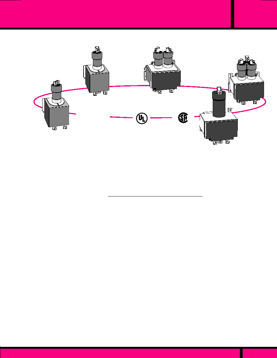
GENERAL SPECIFICATIONS
PAGE 158
WEBSITE: www.magnecraft.com EMAIL:info@magnecraft.com FAX ON DEMAND 1-800/891-2957, DOCUMENT 100
C L A S S
MDR
60 per minute maximum
80% of nominal voltage, Typ. AC & DC coils.
78% of nominal voltage, typ. AC coils
65% of nominal voltage, typ. DC coils
Mercury
.002 ohm M60 & M100
.003 ohm M30 & M35
50 Milliseconds typical
80 Milliseconds typical
2650 V rms
- 35�C to + 60�C Under continuous load.
5,000,000 Operations
250,000 Operations
Class B - 130�C & M35 pressure connectors for
AWG 6-14 wire; M60 pressure connectors for AWG
2 - 12 wire
Vertical
�
10�
Combination of SPST-NO & SPST-NC contact configurations.
available. Other coil voltages available .
COIL
Frequency of Operation:
Pull-in voltage
Dropout voltage
CONTACTS
Material:
Contact resistance:
TIMING
Operate (at nominal voltage)
Dropout (at nominal voltage)
DIELECTRIC STRENGTH
All mutually insulated points to ground:
TEMPERATURE
Operating:
LIFE
Mechanical: (No load)
Electrical (Rated load)
MISCELLANEOUS
Insulation Material:
Mounting:
Options:
PROTECTIVE COIL
COVERS
MDR'S ARE IDEAL FOR SWITCHING RESISTIVE, TUNGSTEN, AND
MOTOR LOADS FOR BOTH AC AND DC APPLICATIONS.
UL Listed
File No. E52197
HERMETICALLY SEALED IN STEEL TUBES
Every contactor tube is hermetically sealed to provide
maximum life, protection to the user from arcing and the
hazards of switching heavy loads with exposed contacts.
LIQUID MERCURY CONTACT
Liquid mercury means a new contact surface after
every operation. Mercury is self-renewing, it cannot
pit, weld, disintegrate or oxidize. The internal
resistance of the contact surfaces typically measure
only a few Milliohms and is ideal for switching large
loads safely.
SPECIFICATIONS MERCURY DISPLACEMENT RELAYS
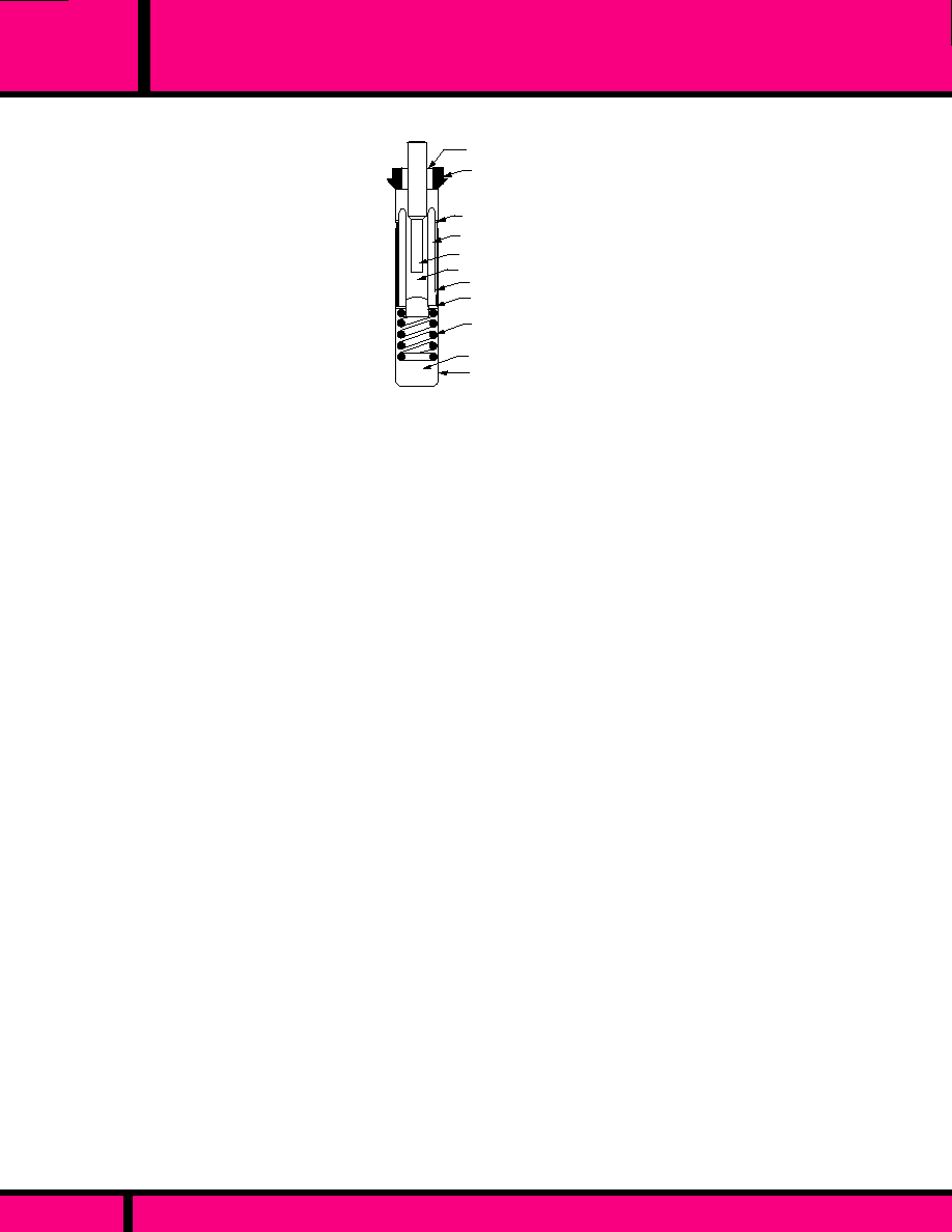
APPLICATION DATA
MDR
C L A S S
PAGE 159
WEBSITE: www.magnecraft.com EMAIL:info@magnecraft.com FAX ON DEMAND 1-800/891-2957, DOCUMENT 100
MERCURY POOL
PLUNGER GUIDE
MAGNETIC LINER
GLASS INSULATOR
WELD
MERCURY DISPLACEMENT TUBE
The sectional view shows our normally open style Mercury Displacement tube with the plunger assembly
floating on the mercury pool.
When the coil power is off, the mercury level is below the electrode tip. No electrical path exists between
the electrode and mercury pool.
When coil power is applied, the plunger is drawn down into the mercury by the pull of the magnetic field.
This action raises the mercury level, so it covers the end of the electrode closing the circuit.
When coil power is turned off, the buoyant force of the mercury causes the plunger assemble to rise,
dropping the mercury level, and breaking the circuit.
Mercury Displacement relays are ideal for adverse environments-
....Where high inrushes are encountered
....Where hermetically sealed contact operation is required because of corrosive, dirty, or moist ambient
conditions.
....Where use does not permit contact maintenance.
....Where reduced noise levels are required.
....where minimum weight and size are desired.
Liquid Mercury Contact - provides a new contact surface with every actuation. Mercury is self-renewing
and does not pit, weld, disintegrate or oxidize.
Hermetic sealing - provides internal and external protection from arcing.
Inert Gas atmosphere - contactor tube is evacuated, then pressurized with a combination of gases which
extinguish arcing and contribute to long life. The pressurized gases provide for a high dielectric withstand-
ing voltage between contact surfaces.
Low Contact Resistance - Large electrode and mercury volume creates low contact resistance and
provides high inrush current capability.
Quiet Operation - Switch clacking normally associated with conventional hard contactors, is eliminated
with mercury displacement tubes and the buffer spring assembly.
The series "ML" is physically the same as the "M" series except for the type of gases used in the
contactor tubes. The "ML" series was developed for use with resistive and tungsten loads on AC power
ONLY. The "ML" series will give much greater life than the "M" series for these types of loads and is
intended for high activation use, such as molding machines or ovens.
The "ML" series, however is not intended for use with motor loads on AC power, or for resistive, tungsten,
or motor loads on DC power. The "M" series, which is our universal series is rated
to be used on all types of loads resistive, tungsten, and motor for both AC and DC power
PRINCIPLE OF OPERATION
APPLICATION DATA
DESIGN FEATURES
APPLICATION OF "M" SERIES VS "ML" SERIES
BUFFER SPRING
ARC QUENCHING ATMOSPHERE
ELECTRODE
CERAMIC LINER
PLUNGER GUIDE
STAINLESS STEEL CAN

1� 3�
1� 3�
120VAC
240VAC
480VAC
600VAC
24VDC
48VDC
125VDC
250VDC
1/2
1/2
1/2
1/2
19.2
19
14
11
27
13.5
5.2
2.6
30*
15
7.5
6
30*
30*
16*
12*
30*
30*
30*
25 **
30*
30*
16*
12*
24
28
14
11.2
3*
7.5*
10*
10*
2*
5*
5*
5*
* UL and CSA Listed ** CSA only
MOTOR
AMPS
RESISTIVE
AMPS
TUNGSTEN
AMPS
HP
PHASE
VOLTAGE
1� 3�
1� 3�
1� 3�
CONTACTOR RATINGS FOR M30A - M30B
1� 3�
DC
DC
DC
DC
COIL Measured @ 25�C
NOMINAL
RESISTANCE
(OHMS)
NOMINAL
INPUT
VOLTAGE
NOMINAL
CURRENT
NOMINAL
POWER
WM30A-120A
PART NUMBER
120 VAC
700
.058
7VA
PART NUMBER SHOWN ALSO AVAILABLE THRU STOCKING DISTRIBUTION
PAGE 160
WEBSITE: www.magnecraft.com EMAIL:info@magnecraft.com FAX ON DEMAND 1-800/891-2957, DOCUMENT 100
CLASS M30
RATED 30 AMPS
SWITCHES RESISTIVE
TUNGSTEN, AND MOTOR LOADS
1 POLE N.O. CONTACT
UL Listed
File No. E52197
30 AMP MERCURY DISPLACEMENT RELAY
MDR
C L A S S
.180 Dia.
(4.6)
2 Holes
1.62
(41.3)
COIL
TERMINALS
4.18
(106.4)
2.03
(51.6)
1.187
(30.2)
2.0
(50.8)
2.12
(58.7)
CONTACTOR
TERMINALS
RECOMMENDED MOUNTING POSITION
�
10�
UP
.531
(13.5)
FOR EXTENDED LOAD LIFE WHEN SWITCHING RESISTIVE AND
TUNGSTEN LOADS ORDER THE ML30-STYLE. OTHER COIL
VOLTAGE AND CONTACT COMBINATIONS AVAILABLE.
CONSULT FACTORY.
Construction in accordance with VDE 0660 and 0110 (Insulation
group 380)
Weigh: 13 ozs. 370 grams

M35 AND M60 DIMENSIONS
MDR
C L A S S
PAGE 161
WEBSITE: www.magnecraft.com EMAIL:info@magnecraft.com FAX ON DEMAND 1-800/891-2957, DOCUMENT 100
2.312
(58.7)
E
.205 Dia.
(5.2)
4 Holes
CONTACTOR
TERMINAL
F
D
1.93
(49.2)
COIL
TERMINALS
3.12
(79.4)
2.28
(58)
2.06
(52.4)
1.77
(45)
3.50
(88.9)
2 POLE
35AMP OR 60 AMP
1.187
(30.2)
.180 Dia.
(4.6)
2 Holes
2.0
(50.8)
2.312
(58.7)
B
A
C
CONTACTOR
TERMINALS
1 POLE
35AMP OR
60 AMP
COIL
TERMINALS
1.62
(41.3)
.205 Dia.
(5.2)
6 Holes
CONTACTOR
TERMINAL
COIL
TERMINALS
3.75
(95.3)
3.12
(79.4)
2.75
(69.9)
1.77
(45)
1.93
(49.2)
J
G
2.28
(58)
3.36
(85.5)
30�
30�
H
3 POLE
35AMP OR 60 AMP
1.375 Max.
(34.9)
4.875 Max.
(123.8)
1.875 Max.
(47.6)
2.218 Max.
(56.3)
4.875 Max.
(123.8)
2.656 Max.
(57.4)
2.218 Max.
(56.3)
4.875 Max.
(123.8)
2.656 Max.
(67.4)
M60B-ML60B
M35B-ML35B
2.375 Max.
(60.3)
5.06 Max.
(128.52)
1.06 Max.
(27)
3.250 Max.
(82.6)
5.062 Max.
(128.52)
1.812 Max.
(46.0)
3.250 Max.
(82.6)
5.062 Max.
(128.52)
1.812 Max.
(46)
2.312 Max.
(58.7)
4.875 Max.
(123.8)
0.937 Max.
(23.8)
3.187 Max.
(81.0)
4.875 Max.
(123.8)
1.687 Max.
(42.9)
3.187 Max.
(81.0)
4.875 Max.
(123.8)
1.687Max.
(42.9)
DIMEN-
SION
M60A-ML60A
A
B
C
D
E
F
G
H
J
M35A-ML35A
* SPST-NC outline is not
shown. The SPST-NC
tube is positioned lower
on the coil so Dimension
A is lower, but the overall
height remains the same.
DIMENSIONS SHOWN IN INCHES AND (MILLIMETERS)
1.50Max. *
(38.1)
5.062 Max.
(128.52)
1.937 Max.
(49.2)
2.281Max.
(57.9)
5.062 Max.
(128.52)
2.781 Max.
(70.6)
2.281 Max.
(57.9)
5.062 Max.
(128.52)
2.781 Max.
(70.6)
1 POLE
2 POLE
3 POLE

PART NUMBER SHOWN ALSO AVAILABLE THRU STOCKING DISTRIBUTION
CLASS WM35 and WM60
SWITCHES RESISTIVE,
TUNGSTEN, AND MOTOR LOADS
STAINLESS STEEL TUBE S
HIGH INRUSH CAPACITY
UL Listed
File No. E52197
PAGE 162
WEBSITE: www.magnecraft.com EMAIL:info@magnecraft.com FAX ON DEMAND 1-800/891-2957, DOCUMENT 100
C L A S S
MDR
35 AND 60 AMP MERCURY DISPLACEMENT RELAYS
1� 3�
1� 3�
120VAC
240VAC
480VAC
600VAC
24VDC
48VDC
125VDC
250VDC
1� 3�
DC
DC
DC
DC
3/4
3/4
3/4
3/4
30
28
21
17
39
19.5
7.4
3.7
60*
30
15
12
50*
50*
40*
20*
60*
60*
60*
50 **
60*
60*
40*
20*
34
28
21
16
* UL and CSA Listed ** CSA only
MOTOR
AMPS
RESISTIVE
AMPS
HP
PHASE
VOLTAGE
1� 3�
1� 3�
1� 3�
"A" (N.O.)
"B" (N.C.)
TUNGSTEN
AMPS
AMPS
45*
22.5
11.2
9
50*
50*
40*
20*
3*
5*
7.5*
7.5*
5*
10*
15*
15*
SEE MDR GENERAL SPECIFICATIONS AND DIMENSIONS.
1� 3�
120VAC
240VAC
480VAC
600VAC
24VDC
48VDC
125VDC
250VDC
1� 3�
DC
DC
DC
DC
1/2
1/2
1/2
1/2
30
19
14
11
27
13.5
5.2
2.6
35*
17
9
7
35*
35*
16*
12*
35*
35*
35*
25 **
35*
35*
16*
12*
34
28
14
11.2
5*
7.5*
10*
10*
3*
5*
5*
5*
* UL and CSA Listed ** CSA only
MOTOR
AMPS
RESISTIVE
AMPS
TUNGSTEN
AMPS
HP
PHASE
VOLTAGE
1� 3�
1� 3�
1� 3�
1� 3�
CONTACTOR RATINGS FOR M60A - M60B
CONTACTOR RATINGS FOR M35A - M35B
2 POLE
Weight
26 Ozs.,
(738 Grams)
3 POLE
Weight
2Lbs. 6 ozs.,
(1078 Grams)
1 POLE
Weight
13 Ozs.,
(370 Grams)
UP
RECOMMENDED MOUNTING
POSITION
�
10�
NOMINAL
POWER
NOMINAL
RESIS-
TANCE
(OHMS)
COIL Measured @ 25�C
WM60A-120A
WM60A-240A
WM60A-24D
WM60AA-120A
WM60AA-240A
WM60AA-24D
WM60AAA-120A
WM60AAA-240A
WM60AAA-24D
WM60B-120A
120 VAC
240VAC, 60HZ
220VAC, 50HZ
24VDC
120 VAC
240VAC, 60HZ
220VAC, 50HZ
24VDC
120 VAC
240VAC, 60HZ
220VAC, 50HZ
24VDC
120VAC
700
2,800
186
218
1,200
98
111
430
64
460
..058
.029
.120
.135
.063
.232
.220
.117
.375
.115
7VA
7VA
3.5W
16.5VA
16.5VA
6W
28VA
28VA
9W
13VA
1 POLE NORMALLY OPEN CONTACT
2 POLE NORMALLY OPEN CONTACTS
3 POLE NORMALLY OPEN CONTACTS
1 POLE NORMALLY CLOSED CONTACT
NOMINAL
INPUT
VOLTAGE
NOMINAL
CURRENT
(AMPS)
NOMINAL
POWER
PART
NUMBERS
NOMINAL
CURRENT
(AMPS)
NOMINAL
RESIS-
TANCE
(OHMS)
COIL Measured @ 25�C
700
2,800
186
218
1,200
98
111
430
64
460
.058
.029
.120
.135
.063
.232
.220
.117
.375
.115
7VA
7VA
3.5W
16.5VA
16.5VA
6W
28VA
28VA
9W
13VA
WM35A-120A
WM35A-240A
WM35A-24D
WM35AA-120A
WM35AA-240A
WM35AA-24D
WM35AAA-120A
WM35AAA-240A
WM35AAA-24D
WM35B-120A
3 POLE NORMALLY OPEN CONTACTS
1 POLE NORMALLY CLOSED CONTACT
NOMINAL
INPUT
VOLTAGE
PART
NUMBERS
120 VAC
240VAC, 60HZ
220VAC, 50HZ
24VDC
120 VAC
240VAC, 60HZ
220VAC, 50HZ
24VDC
120 VAC
240VAC, 60HZ
220VAC, 50HZ
24VDC
120VAC
2 POLE NORMALLY OPEN CONTACTS
1 POLE NORMALLY OPEN CONTACT
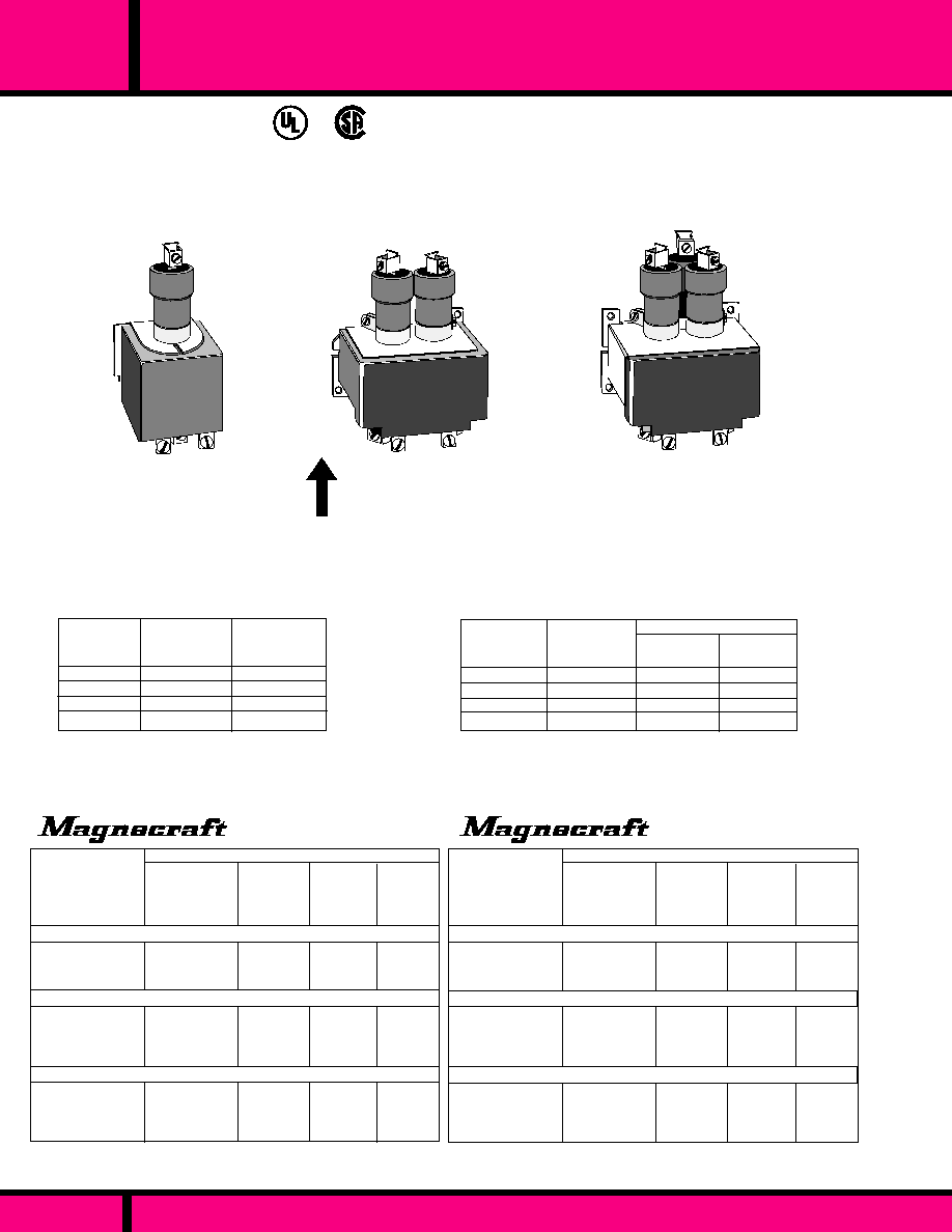
..058
.029
.135
.063
.
.220
.117
.
UL Listed
File No. E52197
CLASS WML35 and WML60
RECOMMENDED FOR MUCH LONGER LIFE
WHEN SWITCHING RESISTIVE AND TUNGSTEN LOADS.
AVAILABLE FOR AC LOADS ONLY.
NOT RECOMMENDED FOR SWITCHING DC LOADS.
PAGE 163
WEBSITE: www.magnecraft.com EMAIL:info@magnecraft.com FAX ON DEMAND 1-800/891-2957, DOCUMENT 100
C L A S S
MDR
35 AND 60 AMP MERCURY DISPLACEMENT RELAYS
3 POLE
Weight
2Lbs. 6 ozs., (1078Grams)
2 POLE
Weight
26 Ozs., (738 Grams)
1 POLE
Weight
13 Ozs., (370 Grams)
UP
RECOMMENDED MOUNTING
POSITION
�
10�
VOLTAGE
60*
30
15
12
60*
60*
60*
50 **
"A" (N.O.)
"B" (N.C.)
AMPS
AMPS
45*
22.5
11.2
9
VOLTAGE
CONTACTOR RATINGS FOR ML60A - ML60B
CONTACTOR RATINGS FOR ML35A - ML35B
* UL and CSA Listed ** CSA only
35*
17
9
7
35*
35*
35*
25 **
RESISTIVE
AMPS
TUNGSTEN
AMPS
RESISTIVE
AMPS
TUNGSTEN
* UL and CSA Listed ** CSA only
120VAC
240VAC
480VAC
600VAC
120VAC
240 VAC
480VAC
600VAC
PART NUMBER SHOWN ALSO AVAILABLE THRU STOCKING DISTRIBUTION
700
2,800
218
1,200
111
430
7VA
7VA
16.5VA
16.5VA
28VA
28VA
..058
.029
.135
.063
.220
.117
120 VAC
240VAC, 60HZ
220VAC, 50HZ
120 VAC
240VAC, 60HZ
220VAC, 50HZ
120 VAC
240VAC, 60HZ
220VAC, 50HZ
120 VAC
240VAC, 60HZ
220VAC, 50HZ
120 VAC
240VAC, 60HZ
220VAC, 50HZ
120 VAC
240VAC, 60HZ
220VAC, 50HZ
COIL Measured @ 25�C
1 POLE NORMALLY OPEN CONTACT
2 POLE NORMALLY OPEN CONTACTS
3 POLE NORMALLY OPEN CONTACTS
NOMINAL
CURRENT
(AMPS)
COIL Measured @ 25�C
700
2,800
218
1,200
111
430
7VA
7VA
16.5VA
16.5VA
28VA
28VA
1 POLE NORMALLY OPEN CONTACT
2 POLE NORMALLY OPEN CONTACTS
3 POLE NORMALLY OPEN CONTACTS
NOMINAL
INPUT
VOLTAGE
PART
NUMBERS
NOMINAL
RESIS-
TANCE
(OHMS)
NOMINAL
POWER
PART
NUMBERS
NOMINAL
INPUT
VOLTAGE
NOMINAL
RESIS-
TANCE
(OHMS)
NOMINAL
POWER
NOMINAL
CURRENT
(AMPS)
WML35A-120A
WML35A-240A
WML35AA-120A
WML35AA-240A
WML35AAA-120A
WML35AAA-240A
WML60A-120A
WML60A-240A
WML60AA-120A
WML60AA-240A
WML60AAA-120A
WML60AAA-240A

PART NUMBER SHOWN ALSO AVAILABLE THRU STOCKING DISTRIBUTION
WEBSITE: www.magnecraft.com EMAIL:info@magnecraft.com FAX ON DEMAND 1-800/891-2957, DOCUMENT 100
NOMINAL
POWER
NOMINAL
CURRENT
(AMPS)
NOMINAL
RESIS-
TANCE
(OHMS)
NOMINAL
INPUT
VOLTAGE
1 POLE NORMALLY OPEN CONTACT
WM100A-120A
WM100A-240A
WM100A-24D
73.5
300
53
33VA
33VA
10W
PART
NUMBERS
120 VAC
240VAC, 60HZ
220VAC, 50HZ
24VDC
.275
.138
.380
COIL Measured @ 25�C
PART NUMBER SHOWN ALSO AVAILABLE THRU STOCKING DISTRIBUTION
VOLTAGE
CONTACTOR RATINGS FOR M100
* NON UL RATING
100
100
100
80*
100
100
80
40
100*
60
30*
24*
100
100
80
40
3
5
15
10*
1.5*
1.5*
1.5*
1.5*
HORSEPOWER
SINGLE PHASE
TUNGSTEN
RESISTIVE
AMPS
AMPS
120VAC
240VAC
480VAC
600VAC
24VDC
48VDC
120VDC
250VDC
PAGE 164
MDR
C L A S S
100 AMP MERCURY DISPLACEMENT RELAYS
RECOMMENDED MOUNTING
POSITION
�
10�
UP
SPECIFICATIONS FOR WM100
COIL
Frequency of Operation:
Pull-in voltage:
Dropout voltage:
CONTACTS
Material:
Contact resistance:
TIMING
Operate (at nominal voltage):
Dropout (at nominal voltage):
DIELECTRIC STRENGTH
Across open Contact:
Coil to Contact:
Contact to Frame:
Coil to Frame:
TEMPERATURE
Operating:
LIFE
Mechanical (No load):
Electrical (Rated load):
MISCELLANEOUS
Insulation Material:
Terminals:
Options:
Weight:
60 per minute max.
80% of nominal voltage, Typ. AC & DC coils.
78% of nominal voltage, typ. AC coils.
65% of nominal voltage, typ. DC coils.
Mercury.
.,001 ohm Typical.
50 Milliseconds typical.
100 Milliseconds typical.
2650 V rms.
2650 V rms.
2650 V rms.
2650 V rms.
- 35�C to + 60�C Under continuous load.
5,000,000 Operations.
100,000 Operations.
Class B - 130�C.
# 1 thru 8 AWG wire.
Coil Voltages from 12VAC to 480VAC, 5VDC.
thru 250VDC. Consult Factory.
15.87 ozs. 450 grams.
3.50 Max.
(88.9)
LOAD TERMINALS
AWG #1 THRU #8 WIRE
.187 Dia.
(4.7)
2 Holes
5.87 Max.
(149)
1.00 Max.
(25.4)
3.37 Max.
(85.59)
1.87
(4.7)
3.00 Max.
(76.2)
2.09 Max.
(53.0)
CLASS WM100
CAPABLE OF SWITCHING 100 AMP
LOADS UP TO 480 VAC /48VDC
AVAILABLE IN 1 POLE N.O.
CONTACTS ONLY.
UL Listed
File No. E52197

SERIES
50 &100 AMP, 2-POLE LIGHTING CONTACTORS
WEBSITE: www.magnecraft.com EMAIL:info@magnecraft.com FAX ON DEMAND 1-800/891-2957, DOCUMENT 100
102,103
The Series 102 and 103 are solenoid types utilizing a DC coils with a full wave bridge
rectifiers which allows the device to operate from an AC supply. Coil power consump-
tion is less than 10 watts for the series 102, less than 20 watts for the 103. The
contacts are Double make type, each set capable of switching and continuously
carrying at least 50 Amps for the series 102 and 100 Amps for the series 103 at up to
480 volts AC. The contactors are typically constructed and wired to be directly
interchangeable with existing hour meter base with separate wire leads for connection
to the controlling device. Because of their compact construction, these contactors can
be adapted to retrofit almost any existing type. Contact our Factory for details.
UP
ORDERING CODE
Typical Type No.
102 JXX -110D
Struthers-Dunn
Series
102 Screw Term., 50 Amp.
103 Screw Term., 100 Amp.
Contact Arrangements
JXX- 2 Pole D.M. N.O
Coil Voltage
DC: 6 to 220 (Add "D")
AC, FULL WAVE RECTIFIED: 12 to 240 (Add "A")
DC: 80% of nominal voltage measured at 25�C
10% of nominal voltage or more @ 25�C
110% of nominal voltage
�
10% Measured @ 25�C
Silver Cadmium Oxide.
60 mS Max. @ Nominal Voltage.
30 mS Max. @ Nominal Voltage.
1500 V rms between all mutually
Insulated current carrying parts and those
parts to ground.
500 VDC Exceeds 1000 Megohms.
-45�C to +65�C @ rated operation.
500,000 Operations no load
100,000 Operations @ Rated Load.
Coil
Load Term.
102 - #8-32
#1/4-20
103 - #8-32
#3/8-18
Wall Mounting..
42 oz., 1.2 kg Grams>
C O I L
Pull-in Voltage:
Dropout Voltage:
Max. allowed voltage:
Coil Resistance:
C O N T A C T S
Contact Material:
TIMING
Operate Time:
Release Time:
DIELECTRIC STRENGTH
All Mutually Insulated Points:
Insulation Resistance:
T E M P E R A T U R E
Temperature Rating:
LIFE EXPECTANCY
Mechanical:
Electrical:
T E R M I N A L S
M I S C E L L A N E O U S
Mounting:
Weight:
RECOMMENDED
MOUNTING POSITION
VOLTAGE
AC (60HZ)
120
240
AC CONTACT RATINGS
VOLTAGE
(DC)
30
DC CONTACT RATING
100
200
200
200
100
100
Series 102 Series 103
RESISTIVE LOAD (AMPS)
RESISTIVE LOAD (AMPS)
3.0
(76.2)
6.0
(152.6)
6.0
(152.6)
WIRING DIAGRAM
UNITS WIRED FOR 50 & 100 AMP LAMP LOAD SERVICE
GENERAL SPECIFICATIONS
PAGE 165
102JXX
103JXX
WATT HOUR METER BOX NOT SUPPLIED WITH 102/
103 CONTACTOR.

7
LATCHING, SEQUENCE
AND
STEPPER RELAYS
5 TO 30 AMPERES
S E C T I O N
7
Page 166

PAGE 167
CONTACT DATA
COIL DATA
GENERAL DATA
DIMENSIONS
APPROVALS
AC - VOLTAGE:
DC - VOLTAGE:
P O W E R :
VA,: (VAC)
WATTS,: (VDC)
AMBIENT TEMPERATURE
OPERATIONAL:
STORAGE:
TIMING VALUES
OPERATE:
RELEASE:
L I F E
MECHANICAL:
ELECTRICAL:
INSULATION
CHARACTERISTICS
DIELECTRIC STRENGTH:
RELAY SERIES
CONTACT CONFIGURATION:
MAXIMUM ALLOWABLE
CONTACT LOAD:
CONTACT MATERIAL:
CONTACT RESISTANCE:
FEATURES
308
255
388ML/285
250ML
H W L
H W L
H W L
1500 V rms
1.40 X 1.53 X 1.90
1.50 X 1.93 X 1.87
2.62 X 1.46 X 4.56
DPDT
10 AMPS @ 120/240VAC
10 AMPS @ 28 VDC
- 45� C to + 70� C
25 ms AC/15 ms DC
25 ms AC/15 ms DC
10 MILLION OPERATIONS
100,000 OPERATIONS
PERMANENT MAG-
NETIC LATCHING
RELAY
SINGLE OR DUAL COIL
3 WAY TERMINALS:
SOLDER, 0.187" Q.C.
OR PLUG IN.
HIGH SENSITIVITY
COILS AVAILABLE
AC OR DC INPUT
PERMANENT MAG-
NETIC LATCHING
RELAY
3 WAY TERMINALS:
SOLDER, 0.187" Q.C.
OR PLUG IN.
AC OR DC INPUT
NO FALSE TRANSFER
WITH 5 TIMES NOMINAL
VOLTAGE PULSE
2 COIL MECHANICAL
LATCHING.
SINGLE LEVEL SOCKET
WIRING
CONTINUOUS DUTY
COILS
BOTH COILS MAY BE
ENERGIZED SIMULTA-
NEOUSLY WITHOUT
DAMAGE.
SILVER CADMIUM OXIDE
GOLD FLASHED
50 MILLIOHMS (INITIAL)
SILVER CADMIUM OXIDE
50 MILLIOHMS (INITIAL)
SILVER CADMIUM OXIDE
OR GOLD DIFFUSED
50 MILLIOHMS (INITIAL)
1500 V rms
1500 V rms
120
12, 24
3.4VA
1.9 WATTS
6 to 240
6 to 125
3.4 VA
1.2 -1.9 WATTS
6 to 240
6 to 125 (250V WITH
SERIES RESISTOR)
5 OP 3 RESET
1.8 OP 1.9 RESET
4PDT
10 AMPS @ 120, 1/3 HP
10AMPS @ /240, 1/2 HP
10 AMPS @ 28 VDC
SPDT, 3PDT, OR UP TO
4 FORM A, OR FORM B .
30AMPS @ 120
CARRY 10A, BREAK 10A.
30AMPS @ /240
CARRY 10A, BREAK 5A.
30 AMPS @ 125 VDC
CARRY 10A, BREAK 0.5A.
- 45� C to + 70� C
25 ms AC/15 ms DC
25 ms AC/15 ms DC
10 MILLION OPERATIONS
100,000 OPERATIONS
- 10� C to + 60� C
25 MILLISECONDS
20 MILLISECONDS
10 MILLION OPERATIONS
100,000 OPERATIONS
1.41 x 1.41 x 3.17
1500 V rms
SILVER CADMIUM OXIDE
GOLD FLASHED
100 MILLIOHMS (INITIAL)
- 45� C to + 70� C
30 MILLISECONDS
30 MILLISECONDS
10 MILLION OPERATIONS
100,000 OPERATIONS
24, 120, 240
12 , 24, 110
6 VA
1.64 WATTS
OCTAL 11 PIN PLUG-IN
DUAL COIL LATCHING
SELF-MAINTAINING
SET AND RESET COILS
MAINTAINS LAST
POSITION WITHOUT
POWER
AC OR DC COILS
DPDT
10 AMPS @ 120 VAC/
30 VDC
H W L
WEBSITE: www.magnecraft.com EMAIL:info@magnecraft.com FAX ON DEMAND 1-800/891-2957, DOCUMENT 100
PAGE 170
PAGE 169
PAGE 171, 172
PAGE 173, 174
PAGE 175, 176
C US
Pending
PAGE NUMBER:
APPLICATION DATA:
Magnecraft
Struthers-Dunn
LATCHING RELAYS TO 10 AMP

WEBSITE: www.magnecraft.com EMAIL:info@magnecraft.com FAX ON DEMAND 1-800/891-2957, DOCUMENT 100
FEATURES
COIL DATA
GENERAL DATA
DIMENSIONS
APPROVALS
AC - VOLTAGE:
DC - VOLTAGE:
P O W E R :
VA,: (VAC)
WATTS,: (VDC)
AMBIENT TEMPERATURE
OPERATIONAL:
STORAGE:
TIMING VALUES
OPERATE:
RELEASE:
L I F E
MECHANICAL:
ELECTRICAL:
INSULATION
CHARACTERISTICS
DIELECTRIC STRENGTH:
RELAY SERIES
CONTACT CONFIGURATION:
MAXIMUM ALLOWABLE
CONTACT LOAD:
CONTACT MATERIAL:
CONTACT RESISTANCE:
CONTACT DATA
1500 V rms
- 10� C to + 50� C (AC)
- 10� C to + 60� C (DC)
25 MILLISECONDS
25 MILLISECONDS
5 MILLION OPERATIONS
100,000 OPERATIONS
SILVER CADMIUM OXIDE
100 MILLIOHMS (INITIAL)
0AMP 120VAC
10AMP 240VAC
10 AMP 28VDC
UP TO 6PDT
OPEN STYLE OR
ENCLOSED STYLE
DUAL COIL, MECHANICAL
LATCHING.
UP TO 6 FORM "C", 3
POLES PER COIL
AC 50/60HZ, & DC COILS
AVAILABLE
SOLDER TERMINALS OR
20 PIN OCTAL PLUG-IN
H W L
1.93 X 1.75X 2.87
88L& 88LCP
H W L
SEQUENCE (STEPPING)
RELAY
SINGLE COIL CONTINU-
OUS DUTY.
CONTACT TRANSFER
ON ENERGIZING OR
DE-ENERGIZING
STROKE OF RELAY
SINGLE LEVEL SOCKET
WIRING
DPDT
5 AMPS @ 120VAC
5 AMPS @ 28 VDC
0.1 AMPS 125 VDC
SILVER CADMIUM OXIDE
50 MILLIOHMS (INITIAL)
6 to 240
6 to 110-125
5 V A
1.8 WATTS
1500 V rms
- 10� C to + 60� C
35 MILLISECONDS
35 MILLISECONDS
5 MILLION OPERATIONS
100,000 OPERATIONS
311
2.62 X 1.46X 3.406
24 to 550
24 to 240
1 8 V A
14 WATTS
H W L
2.625 X 3.00 X 5.00
1500 VAC
FINE SILVER
50 MILLIOHMS (INITIAL)
- 45� C to + 65� C
50 MILLISECONDS
50 MILLISECONDS
500,000 OPERATIONS
100,000 OPERATIONS
C85
DPST-NO or NC &
1SPST-NC
20AMP 120VAC
20AMP 240VAC
20 AMP 30VDC
HEAVY DUTY SEQUENCE
RELAY
POSITIVE ACTION
SEQUENCING CAM
FRONT CONNECTED
TERMINALS
ANY SEQUENCE UP TO 12
STEPS
120
1 2
6 V A
2.5
PAGE 168
PAGE 177, 178
PAGE NUMBER
PAGE 179
PAGE 180
Magnecraft
Struthers-Dunn
LATCHING & STEPPING RELAYS
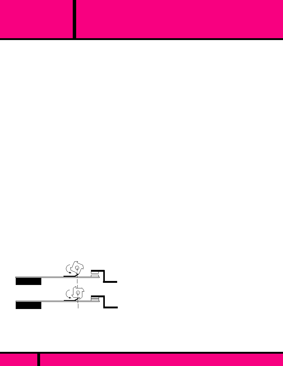
PAGE 169
WEBSITE: www.magnecraft.com EMAIL:info@magnecraft.com FAX ON DEMAND 1-800/891-2957, DOCUMENT 100
SEQUENCE &
LATCHING RELAY
APPLICATION NOTES
WHAT IS A SEQUENCE RELAY:
A Sequence relay is sometimes called an alternator,
stepper, flip-flop, or impulse relay. The relay has the ability
to open and close it's contacts in a preset sequence. All
sequence relays use a ratchet or catch mechanism to
cause their contacts to change state by repeated impulses
to a single coil. Usually, but not always, one pulse will
close a set of contacts, the next will open them, and so on
back and forth. This alternating of open and closed states
has many possible uses.
A Sequence relay requires a pulsed voltage to the coil
of approximately 50 milliseconds for each sequence to
take place. When the coil is pulsed, the relay armature
moves a lever that in turn rotates the ratchet and cams to
the first position in the sequence. This position will remain
as long as another pulse is not introduced to the coil.
The relay is normally comprised of at least two sets of
contacts to allow the contacts to alternate in combinations
of open and closed states, with each pulse of voltage to
the coil.
One example of possible two pole combinations, would be
where one pole remains open and the other pole is closed
with the first pulse applied to the coil. The second pulse
could then reverse the above sequence. The third pulse
could have both poles closed and the fourth pulse could
open both poles. The above example could also have
other sequences, depending upon the amount of teeth in
the ratchet and the amount of lobes on the cams.
Figure 1 shows an example of how cam placement on the
contact blades can change the position of the contacts as
cams are rotated by the ratchet gear.
Closed contact
Open contact
Cam 2
Cam 1
FIGURE 1
SEQUENCE APPLICATIONS:
Some typical applications for sequence relays is turning
one device on and off from a single momentary contact.
SEQUENCE APPLICATIONS CONTINUED:
A typical example is remotely starting and stopping a
conveyer from a single momentary push button. Several
momentary push buttons might be wired in parallel to
control the conveyer from a number of locations.
Another common use for sequence relays is cascade
starting of multiple HVAC or other high start-up load
systems, to limit the high starting current.
WHAT IS A LATCHING RELAY:
Latch relays typically use a permanent magnet or
mechanical catch to hold the contacts in their last
energized position without the need for continued
application of coil power. They are especially useful in
applications where power must be conserved, such as a
battery operated device, or where it is desirable to have
a relay stay in one position if power is interrupted. They
should not be used to control a device that could create
a safety hazard if it were to restart after a power inter-
ruption.
Mechanical latch relays are most often constructed in a
way that will cause them to go to their operate position
when the operate coil is energized regardless of whether
the reset coil is energized or not. This "operate coil
dominant" feature can be useful in applications where a
relay should operate and release like a conventional
relay unless a particular action takes place, at which
time the release coil would drop out, latching the relay in
the operate position. A pallet loader would be a good
example of equipment which might utilize this type of
operation.
Magnetic latching relays are typically designed to be
polarity sensitive. When voltage is momentarily applied
to the coil with a predetermined polarity, the relay will
operate. The relay will remain in the operate position
after power is removed from the coil. A permanent
magnetic is designed to hold the contacts in the operate
position without the need for continued power to the coil.
When the polarity is reversed, and momentarily applied
to the coil, the armature will push away from the coil
overcoming the holding affect of the permanent mag-
netic, causing the contacts to reset. Both single and
dual wound coils use the same principle of operation.
APPLICATION DATA

PAGE 170
W250ML2CPX-6
W250ML2CPX-7
W250ML2CPX-8
W250AML2CPX-8
W250AML2CPX-9
W250AML2CPX-9
12 VDC
24 VDC
110 VDC
24 VAC
120 VAC
240 VAC
8.4 VDC
16.7 VDC
77 VDC
19.2 VAC
96 VAC
192 VAC
8.4 VDC
16.7 VDC
77 VDC
19.2 VAC
96 VAC
192 VAC
88/88
350/350
4000/4000
52/52
1200/1200
3200/3200
1.64 W
1.64 W
1.64 W
6 VA
6 VA
6 VA
RR2KP-U-DC12
RR2KP-U-DC24
RR2KP-U-DC110
RR2KP-U-AC24
RR2KP-U-AC120
RR2KP-U-AC240
DC OPERATED COILS
OPERATE
VOLTAGE
MIN.
RESET
VOLTAGE
MIN.
COIL
RESISTANCE
( EA. COIL)
NOMINAL
POWER
NOMINAL
VOLTAGE
Coil Measured @ 25�C
CROSS REFERENCE
TO
IDEC
PART
NUMBERS
AC OPERATED COILS
Stock Part Numbers shown also available thru Stocking Distribution
WEBSITE: www.magnecraft.com EMAIL:info@magnecraft.com FAX ON DEMAND 1-800/891-2957, DOCUMENT 100
250ML
CLASS
DUAL COIL, 10 AMP LATCHING RELAYS
Dimensions are shown in Inch and (Millimeter).
OUTLINE DIMENSIONS
1.37
(34.79)
2
3
4
5
6
7
8
9
10
11
1
2.33 Max.
(59.2)
2.89 Max.
(73.4)
1.37
(34.79)
Artwork marking side
11 PIN PLUG
2
1
3
4
5
6
8
7
9
10
11
(-)
(-)
(+)
(+)
RESET
WIRING DIAGRAM
OPERATE
SPECIFICATIONS CLASS 250 ML
COIL
Operate Voltage::
Reset Voltage:
Duty cycle @ nominal voltage:
Coil resistance:
Max. allowable voltage:
Coil Insulation:
Duration of Operate & reset pulse:
CONTACTS
Contact material:
Contact resistance:
Minimum Load:
Contact Rating:
TIMING
Operate time:
Release time:
DIELECTRIC STRENGTH
Contacts to coil:
Across open contacts:
Pole to pole:
Contacts to frame:
Insulation resistance:
TEMPERATURE
Ambient Temperature (Operating):
Non operating storage:
SHOCK RESISTANCE
Latched:
VIBRATION RESISTANCE
Operating:
MISCELLANEOUS
Enclosure:
Insulation material:
Operating Position:
Weight:
See Table below. (Measured @ 25�C)
See table below. (Measured @ 25�C)
Dual coil are intermittent duty.
�
10 % measured @ 25 �C
5 X nominal voltage with no false transfer of contacts
during Operate or Reset pulse.
Class "B" system (130�C) per UL STD. 1446
50 mS Minimum.
3/16" silver cadmium oxide, gold flashed.
50 milliohms maximum initial resistance at rated current
12 V @ 100 Milliamps
10 Amps @ 120/240 VAC, 28 VDC
1/3 Hp @ 120 VAC, 1/2 Hp @ 240 VAC.
(AC) 30 mS Max. (DC) 20 mS Max. @ nominal voltage.
(AC) 30 mS Max. (DC) 20 mS Max. @ nominal voltage.
1500 V rms
500 V rms
1500 V rms
1500 V rms
1,000 Megohms min. @ 500 VDC
- 30�C to +70�C
- 30�C to +105�C
10 G's,
5 G's, 10 Hz to 55 Hz
Plastic dust cover with 11 pin octal base.
Molded plastic
Any
170 g ( approx.)
250 ML
MAGNETIC LATCHING RELAY WITH 11 PIN BASE.
OPERATED BY PULSED INPUT AND MAINTAINS LAST POSITION.
CONTACT ARRANGEMENT: DPDT
SEE SECTION 10
F O R
MATING SOCKETS
PENDING
HERMETICALLY SEALED
VERSION AVAILABLE
CONSULT FACTORY

PAGE 171
WEBSITE: www.magnecraft.com EMAIL:info@magnecraft.com FAX ON DEMAND 1-800/891-2957, DOCUMENT 100
285XBXC-120A
285XBXC-12D
285XBXC-24D
285XBXCD-12D
285XBXCD-24D
W388AMLCPX-9
W388MLCPX-6
W388MLCPX-7
W388ML2CPX-6
W388ML2CPX-7
AC OPERATED, SINGLE COIL
DC OPERATED, SINGLE COIL
SINGLE
SINGLE
SINGLE
DUAL
DUAL
STRUTHERS-DUNN
PART
NUMBERS
DC OPERATED, DUAL COIL
NOMINAL
INPUT
VOLTAGE
120 VAC
12 VDC
24 VDC
12 VDC
24 VDC
OPERATE
VOLTAGE
(Or Less)
102 VAC
9.0 VDC
18,0 VDC
9.0 VDC
18.0 VDC
CROSS REFERENCE
TO
POTTER & BRUMFIELD
RESET
VOLTAGE
(Or Less)
102 VAC
9.0 VDC
18.0 VDC
9.0 VDC
18.0 VDC
NOMINAL
RESIS-
TANCE
(OHMS)
10,000
120
470
88/88
350/350
0.8VA
1.2W
1.2W
1.64W
1.64W
KUL11A15S-120
KUL11D15S-12
KUL11D15S-24
KUL11D15D-12
KUL11D15D-24
Measured @ 25�C
COIL
NOMINAL
POWER
EQUIVALENT PART NUMBERS
COIL
CONFIGU-
RATION
PART NUMBERS SHOWN AVAILABLE THRU STOCKING DISTRIBUTION
1
2
3
4
5
6
.28 Typ.
(7.1)
1.40Max.
(35.5)
.187 x .020
(4.76 x 0.51)
QC Terminals Typical
B
A
8
7
9
1.90Max.
(48.4)
1.53 Max.
(38.8)
OUTLINE DIMENSIONS
Dimensions shown are in "Inches" and (Millimeter)
CLASS 388ML/285
10 AMP MAGNETIC LATCH RELAY.
SINGLE OR DUAL COIL LATCHING.
1/3HP @ 120VAC
1/2 HP @ 240VAC
C US
Recognized Component mark for
Canada and the United States.
UL Recognized
File No. E43641
388ML/285
C L A S S
10 AMP MAGNETIC LATCH RELAY

PAGE 172
WEBSITE: www.magnecraft.com EMAIL:info@magnecraft.com FAX ON DEMAND 1-800/891-2957, DOCUMENT 100
7
9
A
B
RESET
+
-
4
6
1
3
OPERATE
-
+
SINGLE COIL ( DC )
7
9
4
6
1
3
9
A
B
6
3
8
RESET
B
A
OPERATE
COMMON
+
-
OPERATE
OPERATE
7
4
1
RESET
8
5
-
+
DUAL COIL ( DC )
SINGLE COIL ( AC )
VIEWED FROM TERMINAL END
SEE SECTION 10
F O R
MATING SOCKETS
COIL
Pull-in Voltage:
Duty Cycle (Nominal V)
Pulse Duration Min.
Max. allowed voltage:
Coil Resistance:
CONTACTS
Contact Material:
Contact configuration:
Contact Rating
TIMING
Operate Time: (@ Nom. V)
Release Time: (@ Nom. V)
DIELECTRIC STRENGTH
Across open contacts
between current carrying
parts to ground:
Insulation Resistance:
TEMPERATURE
Temperature Rating:
LIFE EXPECTANCY
Mechanical:
Electrical:
MISCELLANEOUS
Enclosure:
Weight:
AC: 85%, DC: 75% of nominal voltage
measured at 25�C
Single coil are continuous duty
dual coil are intermittent duty.
30 Milliseconds
5 x Nominal voltage with no false transfer
of contacts during operate or reset pulse.
110% of nominal voltage
�
10% Measured @ 25�C
Silver Cadmium Oxide, Gold Flashed.
DPDT, (3PDT available)
10 Amps @ 120/240VAC, 28VDC
AC: 30 mS max., DC: 20 mS max.
AC: 30 mS max., DC: 20 mS max.
500 V rms
1500 V rms
500 VDC Exceeds 1000 Megohms.
AC: -45�C to +70�C @ Rated Operation.
10 Million Operations no load
100,000 Operations @ Rated Load.
Clear polycarbonate
87 grams approx.
SPECIFICATIONS CLASS 388/285
WIRING DIAGRAM
VIEWED FROM PIN END
388ML/285
C L A S S
10 AMP MAGNETIC LATCH RELAY

SERIES
308
MAGNETIC LATCH 10 AMP, 4 POLE RELAY
ORDERING CODE
Typical Type No.
Series
308 3 way terminals, Magnetic
latch, 10 Amp, 4 pole
Contact Arrangements
XDX (4 Form "C")
Construction Style
Enclosed, 3 way terminals - CODE C
Options
10 Amp contacts Standard - NO CODE
Gold diffused contacts - CODE G
Indicator Lamp - CODE L
Manual Actuator - CODE M
Printed Circuit Terminals - CODE T
5 Amp contacts (Silver) - CODE Y
Coil Voltage
AC: 6, 12, 24, 48, 120, 240 (Add "A")
DC: 6, 12, 24, 48, 115, 125 (Add "D")
308 XDX C LMY -120A
Dual Coil Construction available. Consult Factory.
Struthers-Dunn
9
5
1
4
8
12
3
7
11
10
6
2
-
+
-
14
13
OPERATE
RESET
+
SINGLE COIL DC OPERATED
9
5
1
4
8
12
3
7
11
10
6
2
COMMON
13
14
OPERATE
RESET
1.50
(38.1)
1.31
(33.3)
0.218
(5.53)
1.87
(47.4)
1.93
(49.0)
PAGE 173
WEBSITE: www.magnecraft.com EMAIL:info@magnecraft.com FAX ON DEMAND 1-800/891-2957, DOCUMENT 100
SINGLE COIL AC OPERATED
Dimensions shown are in INCHES and (millimeters)
WIRING DIAGRAM
(VIEWED FROM TERMINAL END)
The series 308 relay combines the basic features of the 284 series relay into a
permanent magnet latch relay. It is available with a single wound AC or DC coil.
To operate the single-wound DC coil, voltage of proper polarity is applied to the coil,
and reset when the polarity is then reversed. For AC coils, power is applied through
the operate diode or the reset diode to provide the required function.
MANUAL PUSH
B U T T O N
ACTUATOR (OPTIONAL)
OUTLINE DIMENSIONS
0.187
(4.74)
0.28
(7.11)

C O I L
Pull-in Voltage:
Dropout Voltage:
Max. allowed voltage:
Coil Resistance:
C O N T A C T S
Contact Material:
TIMING
Operate Time:
Release Time:
DIELECTRIC STRENGTH
All Mutually Insulated Points:
Insulation Resistance:
T E M P E R A T U R E
Temperature Rating:
LIFE EXPECTANCY
Mechanical:
Electrical:
M I S C E L L A N E O U S
Enclosure:
Weight:
AC: 85%, DC: 75% of nominal voltage
measured at 25�C
10% of nominal voltage or more @ 25�C
110% of nominal voltage
�
10% Measured @ 25�C
Silver Cadmium Oxide.
AC: 25mS, DC: 15mS @ nom. Voltage
AC: 25mS, DC: 15mS @ nom. Voltage
500 V rms across open contacts
1500 V rms between current carrying
parts
500 VDC Exceeds 1000 Megohms.
-45�C to +70�C @ Rated Operation.
10 Million Operations no load
100,000 Operations @ Rated Load.
Clear polycarbonate
5.0 oz. approx..
NOTE: For 220 VDC to 250 VDC coils, use a 8,200
, 5 Watt resistor in series with
110 VDC to 125 VDC relay coils.
Nominal
Voltage
Resistance
Ohms
�
10%
Resistance
Ohms
�
10%
Current (MA)
6
12
24
48
120AC or
115-125DC
240AC*
3.4VA
3.4VA
3.4VA
3.4VA
3.4VA
3.4VA
AC
DC
Power
Consumption
LOAD
Resistive Motor
Load 80% pF.
30VDC
120VAC
240VAC
10A
10A
1/3Hp
10A
1/2Hp
Maximum total load for 4 pole relays is 30 Amps @
120 VAC, 20 Amps @ 240 VAC.
COIL SPECIFICATIONS @ 25�C
CONTACT RATINGS
GENERAL SPECIFICATIONS
SERIES
308
MAGNETIC LATCH 10 AMP, 4 POLE RELAY
PAGE 174
WEBSITE: www.magnecraft.com EMAIL:info@magnecraft.com FAX ON DEMAND 1-800/891-2957, DOCUMENT 100
3
12
48
-
870
4700
AC
30
120
480
1920
8200
-*
DC
560
230
115
-
31
12
AC
200
100
50
25
13-15
-*
DC
1.2W
1.2W
1.2W
1.2W
1.9W
1.9W

B255
SERIES
300 VOLT LATCHING PLUG-IN RELAYS
R
UL Recognized
File No. E13224
R
THE SERIES B255 IS A TWO COIL LATCHING VERSION OF THE GENERAL PURPOSE
TYPE 219 RELAY. WHEN THE OPERATE COIL IS MOMENTARILY ENERGIZED, THE
RELAY MECHANICALLY LATCHES IN THE ENERGIZED POSITION AND REMAINS IN THE
ENERGIZED POSITION WITH THE POWER REMOVED FROM THECOIL. THE SECOND
COIL WHEN MOMENTARLY ENERGIZED, PROVIDES ELECTRICAL RESET OF THE
CONTACTS. ALL CONTACTS OPERATE FROM A COMMON ARMATURE TO PREVENT
CONTACT OVERLAPPING. COILS ARE RATED FOR CONTINUOUS DUTY. NUCLEAR
QUALIFIED VERSIONS ARE AVAILABLE. CONTACT THE FACTORY FOR DETAILS.
U
V
LM
33
SUFFIX
OPTIONS
130�C Coil
Coil Suppression
Light & Actuator
Fine Silver-Gold Diffused Bifurcated Contacts
B255 XCX P LM -
Series
B255 2 Coil Latch plug-in
Contact Arrangements
XBX DPDT
XCX 3PDT
ABX SPST-NO & 2 Form C
BXB DPST-NO & 2 Form B
Standard Features
Polycarbonate Cover- CODE "P"
Optional Features
Indicator Lamp across both coils - CODE "L"
Manual Actuator- CODE "M"
Perm. Magnet Blowout- CODE "69"
Coil Voltage
Coil Voltages & Frequencies must be specified.
Note: For time delay on energizing reset coil,
specify 256 series in lieu of B255
ORDERING CODE
Typical Type No.
DC RELAYS, 1.8 WATTS (2.5 W @ 125VDC)
Struthers-Dunn
PAGE 175
WEBSITE: www.magnecraft.com EMAIL:info@magnecraft.com FAX ON DEMAND 1-800/891-2957, DOCUMENT 100
CONTACTS
6
1
7
12
B255XBXP
(DPDT )
6
1
7
12
B255XCXP
(3 PDT)
6
1
7
12
B255ABXP
(DPDT + 1 N.O. )
RESET
OPERATE
OPERATE
RESET
RESET
OPERATE
6
1
7
12
B255BXBP
(2 N.O. + 2 N.C. )
RESET
OPERATE
B255ABXP
B255XBXP
B255XCP
B255BXBP
DPDT + 1 NO
DPDT
3PDT
2 NO + 2 NC
WIRING DIAGRAMS
(VIEWED FROM TERMINAL END)
TYPE
4.56
(115.8)
12
1
6
7
LOCKING DEVICE
2.625
(66.67)
1.468
(37.28)
3.75
(95.25)
OUTLINE DIMENSIONS
Dimensions shown Inch & (Millimeters)
SEE SECTION 10
FOR
MATING SOCKETS
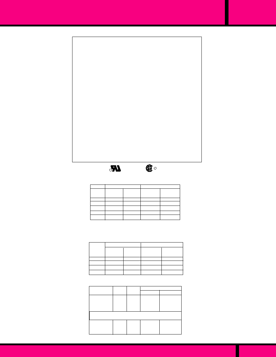
WEBSITE: www.magnecraft.com EMAIL:info@magnecraft.com FAX ON DEMAND 1-800/891-2957, DOCUMENT 100
300 VOLT LATCHING PLUG-IN RELAYS
B255
SERIES
85% of Nominal Voltage
80 % of Nominal Voltage
110% of nominal, voltage
Silver Cadmium Oxide, & Gold Diffused
(Standard)
25 mS Max. @ Nominal Voltage.
20 mS Max. @ Nominal Voltage.
1500 V rms
1/4" over surface, 1/8" thru Air
-10�C to +60�C
10 Million Operations no load
100,000 Operations @ Rated Load.
500,000 Operations 1/2 Rated Load.
Clear polycarbonate.
215 g (7.58 oz.) APPROX.
GENERAL SPECIFICATIONS
COIL
Pull-in, min. AC
Pull-in min. DC
Overvoltage, max.
CONTACTS
Contact Material:
TIMING
Operate Time: (operate coil)
Release Time: (Reset coil
energized)
DIELECTRIC STRENGTH
All Mutually Insulated Points:
Insulation :
TEMPERATURE
Rated Operation:
LIFE EXPECTANCY
Mechanical:
Electrical:
MISCELLANEOUS
Enclosure:
Weight:
R
UL Recognized
File No. E13224
R
3.0
14.5
52.0
1450
5000
840
256
150
26.5
4.8
1.10
4.20
15.5
540
1815
6
12
24
120
240
Resistance
Ohms
�
10%
Coil Power
(mA)
Nominal
Voltage
Resistance
Ohms
�
10%
Coil Power
(mA)
800
410
200
45.0
13.2
RESET COIL (3VA) OPERATE COIL (5VA)
*AC COIL, 50/60 HZ
COIL SPECIFICATIONS @ 25�C
Current inrush on all AC coils is less than twice the listed
milliamperes ratings as shown in the AC coil data table.
*Currents shown in table measured at 60 Hz.
6
12
24
115/125
Nominal
Voltage
DC relays, 1.8 Watts (2.5 W @ 125VDC)
DC COIL DATA
RESET COIL 1.4W)
385
189
96.0
20.0
15.5
63.5
250
6200
286
141
80
14.4
21.0
85.0
300
8000
Resistance
Ohms
�
10%
Coil Power
(mA)
OPERATE COIL (1.8W)
Resistance
Ohms
�
10%
Coil Power
(mA)
10A
3A
1A
3A
0.1A
0.5A
1.5A
150 mA
0.5A
24 VDC
120 VAC
240 VAC
28 VDC
125 VDC
125 VDC SM
125 VDC DM
250 VDC SM
250 VDC DM
VOLTS
MAKE
30A
30A
30A
30A
30A
30A
30A
30A
30A
10A
10A
10A
10A
10A
10A
10A
10A
10A
10A
10A
5A
10A
0.5A
1.5A
4A
0.5A
1.5A
RESISTIVE
INDUCTIVE
CARRY
BREAK
CONTACT RATINGS
** For versions with suffix "69"
Permanent Magnet Blowouts
**Relays with Code 69 feature ( Check with factory for UL & CSA Listing).
PAGE 176
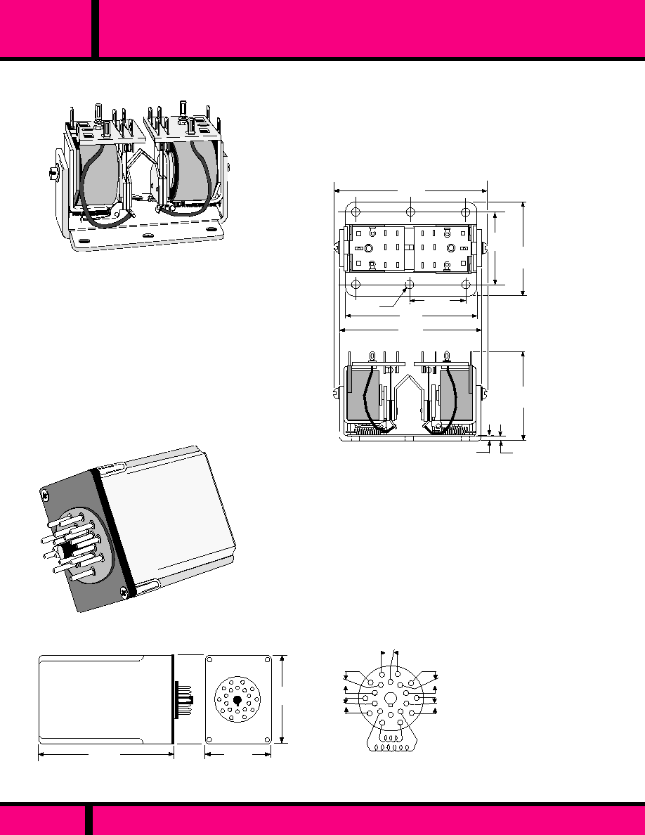
88L
CLASS
DUAL COIL, 10 AMP LATCHING RELAYS
CLASS 88L
OPEN STYLE DUAL COIL
LATCHING RELAY
RATED 10 AMPS
1.75 Max.
(44.45)
1.37 Max.
(34.8)
2.87 Max.
(72.9)
1.00 Typ.
(25.4)
.156 Dia.
(3.96)
.100
(2.54)
.130
(3.30)
2.37 Max.
(60.2)
2.68 Max.
(68.07)
1.93 Max,
(49.0)
OUTLINE DIMENSIONS
Dimensions shown Inchs & (Millimeters)
CLASS 88LCP
ENCLOSED STYLE DUAL
COIL LATCHING RELAY
RATED 10 AMPS
3.562
(90.47)
1.75
(44.45)
2.375
(60.3)
2
4
7
11
16
20
12
5
3
6
8
9
13
14
15
17
1
18
10
19
5PDT
WIRING DIAGRAMS
Shown from Pin End
20 Pin Octal Socket mates with
Magnecraft chassis mount socket
70-454 or equivalent.
PART NUMBER 70-454, 20 PIN SOCKET AVAILABLE.
CALL FACTORY FOR CURRENT QUOTE.
PAGE 177
WEBSITE: www.magnecraft.com EMAIL:info@magnecraft.com FAX ON DEMAND 1-800/891-2957, DOCUMENT 100
NOTE: Applying a momentary pulse to that coil which
was NOT LAST ENERGIZED, will cause a transfer of
all contacts. The mechanical latch will maintain all contacts
in the last transferred position even after the coil is de-
energized or power is interrupted. Re-transfer of contacts
can be accomplished by a momentary pulse to the other coil.

WEBSITE: www.magnecraft.com EMAIL:info@magnecraft.com FAX ON DEMAND 1-800/891-2957, DOCUMENT 100
COIL Measured at 25�C
CONTACT
CONFIGU-
RATION
PART
NUMBERS
NOMINAL
RESISTANCE
(OHMS)
AC OPERATED, OPEN STYLE, SOLDER TERMINAL
DC OPERATED, OPEN STYLE, SOLDER TERMINAL
AC OPERATED, ENCLOSED 20 PIN OCTAL PLUG-IN
4PDT
4PDT
5PDT
120 VAC
12 VDC
50
NOMINAL
POWER
NOMINAL
VOLTAGE
CROSS REFERENCE
TO
POTTER & BRUMFIELD
Stock Part Numbers shown below also available thru stocking distriubution
Part Numbers without a "W" prefix are Non-Stock Relays .
Other AC & DC coil voltages and contact combinations up to 6
poles are available on special order. Consult Factory
80% of nominal voltage or less. for DC coils
85% of nominal voltage or less for AC coils
50/60 Hz operation, Measured @ 25�C
�
10 % measured @ 25 �C
6VA for AC coils, 3 Watts for DC coils.
Intermittent actuation. min. pulse time 50mS @
nominal voltage. Max. pulse time 2 Minutes for
AC coils, 5 Minutes for DC coils.
3/16" silver cadmium oxide, gold flashed.
50 m
max. initial resistance @ rated current
25 mS or less at nominal voltage.
25 mS or less at nominal Voltage.
1500 V rms
1000 V rms
1500 V rms
1500 V rms
1000 megohms min. 500 VDC
-10�C to +50�C (AC), -10�C to +60�C (DC)
-30�C to 105�C
5 G's
20 G's
5 G's, 10 Hz to 55 Hz
5 G's, 10 Hz to 55 Hz
6 holes, 5/32" dia.for mounting plate to flat surface
or 20 pin style plug-in.
Fiberglass melamine
Open style are Solder type standard, will also accept Q.C. terminals
size .110. (Amp "Faston" or equivalent) Enclosed styles have 20
nickel plated brass pins
"See-through " clear, polycarbonate plastic.
Any
Open Style: 6-1/2 ozs. 184.3 grams approx..
Enclosed style: 8 ozs. 226.8 grams
COIL
Pull-in voltage:
Coil resistance:
Nominal power:
Duty:
CONTACTS
Contact material:
Contact resistance:
TIMING
Operate time:
Release time:
DIELECTRIC STRENGTH
Contacts to coil:
Across open contacts:
Pole to pole
Contacts to frame:
Insulation resistance:
TEMPERATURE
Ambient Temperature (Operating):
Non operating (storage):
SHOCK RESISTANCE
Operating:
Non operating:
VIBRATION RESISTANCE
Operating
Non operating:
MISCELLANEOUS
Mounting:
Insulation material:
Terminals
Enclosure:
Operating Position:
Weight:.
_
_
6 VA
2.4W
6 VA
KB-17AG-120
KB-17DG-12
KBP-20AG-120
120 VAC
W88ALX-4
88LX-2
88ALCPX-23
CLASS
88L
DUAL COIL, 10 AMP LATCHING RELAYS
PAGE 178
SPECIFICATIONS CLASS 88L RELAYS

SEE SECTION 10
FOR
MATING SOCKETS
NOTE: Relays with other coil characteristics may be supplied
to meet specific application requirements.
250VDC operation may be obtained by wiring a 6,200
,
5 Watt resistor in series with the 110-125VDC coil. The
resistor must be mounted external to the A311.
AC COIL , 50/60Hz
6
12
24
120
240
15.5
63.5
250
970
6200
1.1
4.2
15.5
540
1815
Nominal
Voltage
Nominal
Voltage
Resistance
Ohms
�
10%
Resistance
Ohms
�
10%
6
12
24
48
110-125
COIL SPECIFICATIONS @ 25�C
DC COIL
2.625
(66.6)
11
12
1
5
2
3
4
6
7
8
9
10
LOCKING
CLIP
2.593
(65.5)
1.468
(37.2)
.435
(11)
3.406
(86.5)
6
1
7
12
OPERATE
A311XBXP
A311XBXPR *
(DPDT )
*Transfer on Release
WIRING DIAGRAM
Viewed from Pin Side
Series
A311 Industrial plug-in ,
Sequence Relay, 5 Amp, DPDT
Contact Arrangements
XBX ( 2 Form C)
Standard Features
Plug-in with Polycarbonate Cover - CODE P
Contact Transfer
When coil is energized - NO CODE
when coil is de-energized CODE R
Options
Indicator Lamp - CODE L
Coil Suppression - CODE V
Coil Voltage
AC: 6, 12, 24, 120, 240 (Add "A")
DC: 6, 12, 24, 48, 110-125 (Add "D")
ORDERING CODE
Typical Type No.
A311 XBX P R L -120A
Resistive
Max. Inrush
0.1A
0.25A
5A
12A
5A
12A
115VDC
30VDC
120VAC
LOAD
CONTACT RATINGS
A311
SERIES
INDUSTRIAL PLUG-IN SEQUENCE (STEPPER), 5 AMP
Struthers-Dunn
PAGE 179
WEBSITE: www.magnecraft.com EMAIL:info@magnecraft.com FAX ON DEMAND 1-800/891-2957, DOCUMENT 100
The A311 Series Relay is a sequencing version of the 219 series
general purpose relay. Contacts transfer on each Impulse to the coil.
Models are available with contacts transferring when coil is energized
or when de-energized. A double cam movement, one cam per snap
switch, allows one or both contacts to be energized or de-energized
with the cam rotating one half-step when the coil is energized and the
other half step when the coil is de-energized assures reliable sequencing
of the two SPDT snap switches.
GENERAL SPECIFICATIONS
85% of Nominal Voltage
80 % of Nominal Voltage
110% of nominal, voltage
Silver Cadmium Oxide
35 mS Max. @ Nominal Voltage.
35 mS Max. @ Nominal Voltage.
500 V rms
1500 V rms
1000 M
min. @ 500 VDC
-10�C to +60�C
5 Million Operations no load
100,000 Operations @ Rated Load.
Clear polycarbonate.
190 g (6.70 oz.) approx.
UL Recognized
File No. E7104
COIL
Pull-in, min. AC
Pull-in min. DC
Overvoltage, max.
CONTACTS
Contact Material:
TIMING
Operate Time: (operate coil)
Release Time: (Reset coil energized)
DIELECTRIC STRENGTH
Across open Contacts:
Between mutually insulated current
carrying parts & those parts to ground:
Insulation Resistance :
TEMPERATURE
Rated Operation:
LIFE EXPECTANCY
Mechanical:
Electrical:
MISCELLANEOUS
Enclosure:
Weight:

PAGE 180
WEBSITE: www.magnecraft.com EMAIL:info@magnecraft.com FAX ON DEMAND 1-800/891-2957, DOCUMENT 100
AC COIL , 50/60Hz
62
-
1,475
6,100
-
-
27
771
-
3,290
14,700
22,000
Nominal
Voltage
Nominal
Voltage
Resistance
Ohms
�
10%
Resistance
Ohms
�
10%
DC COIL
24
120
110-125
240
440
550
24
120
110-125
240
440
550
COIL SPECIFICATIONS @ 25�C
SERIES
SCREW TERMINAL SEQUENCE RELAY, 20 AMP, 2 POLE
10A
0.25A
20A
1.0A
20A
20A
240VAC
120VAC
24VAC
AC
DC
C85
CONTACT RATINGS
ORDERING CODE
Typical Type No.
C85 AXA H3 -120A
Series
C85 Screw Terminal
Sequence Relay, 20 Amp, 2 Pole
Contact Arrangements
AXA 1 S.B.-N.O. & 1 S.B.-N.C.
BXX 2 S.B.-N.O.
Options
Open style construction - NO CODE
Sheet Metal Housing (consult Factory)
For Dimensions) -CODE H3
7, 9, 10, 11, 12 Tooth ratchet-Consult Factory
Coil Voltage
AC: 24, 120, 240, 440, 550 (Add "A")
DC: 24,110-125, 240 (Add "D")
RATCHETS: 8 Tooth Standard. ( 7, 9, 10, 11, and 12 are
Special Order). Consult Factory.
Non-Standard Coils, Specify requirement, Consult Factory.
Struthers-Dunn
85% of Nominal Voltage
80 % of Nominal Voltage
110% of nominal, voltage
Fine Silver
50 mS Max. @ Nominal Voltage.
50 mS Max. @ Nominal Voltage.
1500 V rms
1500 V rms
1000 M
min. @ 500 VDC
-45�C to +65�C
500,000 Operations no load
100,000 Operations @ Rated Load.
# 10-32 Studs with Hardware
3 clearance holes for # 8 screws
325 g (11.46 oz.)
COIL
Pull-in, min. AC
Pull-in min. DC
Overvoltage, max.
CONTACTS
Contact Material:
TIMING
Operate Time: (operate coil)
Release Time: (Reset coil energized)
DIELECTRIC STRENGTH
Across open Contacts:
Between mutually insulated current
carrying parts & those parts to ground:
Insulation Resistance :
TEMPERATURE
Rated Operation:
LIFE EXPECTANCY
Mechanical:
Electrical:
MISCELLANEOUS
Terminals:
Mounting:
Weight
GENERAL SPECIFICATIONS
RELAY
STEP
1 2 3 4 (REPEAT)
CONTACT A 0 X 0 X
C85AXA
CONTACT B X 0 X 0
CONTACT A 0 X 0 X
C85BXX
CONTACT B 0 X 0 X
0 = CONTACT OPEN X = CONTACT CLOSED
STANDARD CONTACT SEQUENCES
WIRING DIAGRAM
2.37
(60.1)
3.00
(76.2)
4.37
(110.9)
5.00
(127)
.312
(7.92)
2.62
(66.5)
.312
(7.92)
The C85 Series Relay is a base mounted, screw terminal, open style sequencing relay.
This two pole relay has a single coil which operates a ratchet wheel. Control cams, on the
ratchet wheel shaft, step from one position to the next on each Impulse to the coil. A 50
millisecond pulse will step the relay. Coils are for momentary duty only. The C85 may be
supplied in any sequence up to 12 steps. Contacts are single throw.
C85

S E C T I O N
8
HIGH VOLTAGE
ELECTROMECHANICAL AND REED
RELAYS
5KV TO 10KV
8
Page 181

RELAY SERIES
FEATURES
DIMENSIONS
AC - VOLTAGE:
DC - VOLTAGE:
WATTS,: (VDC)
GENERAL DATA
CONTACT CONFIGURATION:
MAXIMUM ALLOWABLE
CONTACT LOAD:
CAPACITANCE (No shield)
Across open contacts:
CONTACT MATERIAL:
CONTACT RESISTANCE:
COIL DATA
CONTACT DATA
SWITCHES LOADS UP TO 1KVA.
@ 5000 VOLTS
DESIGNED WITH A UNIQUE
DOUBLE MAKE & BREAK CONTACT
DESIGN WITH GAP OF 0.40".
EXCELLENT HIGH VOLTAGE ARC-
OVER RESISTANCE BETWEEN
C O N T A C T S .
SOLDER TERMINAL DESIGN.
EPOXY SEALED FOR EXTRA
PROTECTION FROM HIGH
VOLTAGE ARC OVER
CHASSIS MOUNTING WITH
SOLDER TERMINALS.
EXTRA WIDE SEPARATION
BETWEEN COIL AND OUTPUT
C O N T A C T S .
SWITCHES UP TO 5 MILLIAMP
LOADS @ 10,000 V
EPOXY SEALED FOR EXTRA
PROTECTION FROM HIGH
VOLTAGE ARC- OVER
CHASSIS MOUNTING
WITH SOLDER TERMINALS.
EXTRA WIDE SEPARATION
BETWEEN COIL AND OUTPUT
C O N T A C T S .
SWITCHES UP TO 10 MILLIAMP
LOADS @ 5000 V
SPDT-DB-DM
1 KVA, 5000 VDC
200 mA, 5000 V
1 Amp, 1000 V
-
SPST-NO
50VA, 10,000 VDC
5 mA
2.0 pf
SPST-NO
50VA, 5000 VDC
10 mA
2.0 pf
TUNGSTEN
200 MILLIOHMS (INITIAL)
TUNGSTEN
200 MILLIOHMS (INITIAL)
SILVER ALLOY GOLD FLASHED
100 MILLIOHMS (INITIAL)
7,500 V rms & contacts to ground
3,000 V rms
8,500 V rms
6,000 VDC
6,000 VDC
1
2,000VDC
12,000 VDC
A V A I L A B L E
24 VDC
5 WATTS
NOT AVAILABLE
6, 12, 24 VDC
500-580 mW
NOT AVAILABLE
24 VDC
1.5 WATTS
- 40�C to + 85� C
-60�C to + 105�C
45 MILLISECONDS
20 MILLISECONDS
10 G's -11mS, 1/2 sinewave
10 G'S - 10 to 55 HZ
5 MILLION OPERATIONS
100,000 OPERATIONS
- 40�C to + 85�C (1 Form A)
- 40�C to + 40�C (1 Form B)
-60�C to + 105�C
3 MILLISECONDS
2 MILLISECONDS
2.0 MILLISECONDS
30 G's -11mS 1/2 sinewave
10 G's - 10 to 1000 HZ
10 MILLION OPERATIONS
1,000,000 OPERATIONS
- 40�C to + 85� C
-60�C to + 105�C
3 MILLISECONDS
2 MILLISECONDS
2 MILLISECONDS
30 G's - 11mS, 1/2 sinewave
10 G's -10 to 1000 HZ
10 MILLION OPERATIONS
1,000,000 OPERATIONS
H W L
0.75 X .875 X .450
H W L
H W L
APPROVALS
0.75 X .875 X 4.50
2.28 X 2.21 X 3.12
102HV
102V
158
DIELECTRIC STRENGTH
Across open contacts:
Coil to ground:
Between all mutually
insulated points:
INSULATION
CHARACTERISTICS
AMBIENT TEMPERATURE
OPERATIONAL:
STORAGE
TIMING
OPERATE:
RELEASE:
BOUNCE:
SHOCK (Non-operating):
VIBRATION:
L I F E
MECHANICAL:
ELECTRICAL:
PAGE 182
WEBSITE: www.magnecraft.com EMAIL:info@magnecraft.com FAX ON DEMAND 1-800/891-2957, DOCUMENT 100
10,000 V0LTS
5000 V0LTS
5000 V0LTS
PAGE 184
PAGE 184
PAGE 183
PAGE NUMBER
Magnecraft
Struthers-Dunn
HI-VOLTAGE RELAYS 5KV TO 10KV

PART
NUMBERS
CONTACT
CONFIGURA-
TION
SPDT-DB-DM
24VDC
NOMINAL
INPUT
VOLTAGE
120
NOMINAL
COIL
RESISTANCE
NOMINAL
POWER
5 Watts
Coil Measured at 25�C
HIGH VOLTAGE SWITCHING RELAYS
2.281
(57.94)
1.125
(28.58)
1.750
(44.45)
.196 ( 4.98) dia.
2 Holes
3.125 Max.
(79.38)
2.281
(56.34)
OUTLINE DIMENSIONS
DIMENSIONS SHOWN ARE IN INCHES AND (MILLIMETERS)
158
C L A S S
PART NUMBERS SHOWN ALSO AVAILABLE THRU STOCKING DISTRIBUTION.
CLASS 158
SPDT-DB-DM CONTACT CONFIGURATION
SWITCHES LOADS UP TO 1KVA
COIL
Coil Dissipation:
CONTACTS
Contact Material:
Contact Configuration:
Switching Voltage max.:
Contact Rating:
DIELECTRIC STRENGTH
Across open contacts:
Contact to Coil:
Contact to Frame:
Insulation Resistance:
TEMPERATURE
Operating:
LIFE EXPECTANCY
Electrical:
Mechanical:
MISCELLANEOUS
Mounting:
Weight:
DC 5 Watts.
Silver alloy, Gold Flashed, 1/4" dia.
SPDT-DB-DM
5000 VDC
200 mA @ 5000 VDC
1 Amp @ 1000 VDC
7500 V rms
8500 V rms
3000 V rms
500 VDC, Exceeds 100 M
-40�C to +85�C
100,000 ( Rated Load)
5 Million Operations (No Load) Min.
Bracket with 2 Clearance holes 0.196 dia.
212.6 grams (7.48 oz.)
SPECIFICATIONS CLASS 158
WEBSITE: www.magnecraft.com EMAIL:info@magnecraft.com FAX ON DEMAND 1-800/891-2957, DOCUMENT 100
PAGE 183
VIEWED FROM PIN END
WIRING DIAGRAM
SPDT-DB-DM
SPDT
FIELD
INSTALLABLE
JUMPER
WIRE
W158HVX-1

102V
C L A S S
HIGH VOLTAGE SWITCHING RELAYS
W102VX-49
W102VX-50
W102VX-51
W102HVX-3
70
250
1000
400
5,000 VOLTS NORMALLY OPEN
10,000 VOLTS NORMALLY OPEN
PART NUMBERS SHOWN ALSO AVAILABLE THRU STOCKING DISTRIBUTION.
NOTE: Other voltages and contact combinations available. Contact Factory.
Pull-in is measured at 75% of nominal voltage or less, at 25�C
Weight: 49.2 grams, (1.74 oz.)
PART
NUMBERS
SPST-NO
SPST-NO
SPST-NO
SPST-NO
CONTACT
CONFIGURA-
TION
NOMINAL
INPUT
VOLTAGE
6 VDC
12 VDC
24 VDC
24 VDC
NOMINAL
COIL
RESISTANCE
500 mW
580 mW
580 mW
1.5 Watts
Coil Measured at 25�C
NOMINAL
POWER
PAGE 184
WEBSITE: www.magnecraft.com EMAIL:info@magnecraft.com FAX ON DEMAND 1-800/891-2957, DOCUMENT 100
3.40
(86.5)
0.875
(22.2)
.156 dia.
(3.9)
0.28
(7.1)
4.12
(104.7)
4.50
(114.3)
DIMENSIONS SHOWN ARE IN INCHES AND (MILLIMETERS)
.645
(16.3)
1.10
(27.9)
0.25
(6.35)
1.50
(38.1)
Coil Terminals
.125 x .025
.125
(3.18)
0.08
(2.03) DIA.
Typical.
0.75
(19.0)
Do not hook wire heavier than #22 AWG. Excess stress on
terminals could cause damage to internal components
OUTLINE DIMENSIONS
CLASS 102V
EPOXY ENCAPSULATED HIGH VOLTAGE REED.
SPST-NO TUNGSTEN CONTACTS
SWITCHES LOADS UP 10 mA @ 5000 Volts DC
CLASS 102HV
Same as above except:
Switches 10,000 Volts with Loads up to 5 mA DC

S E C T I O N
9
Page 185
SENSITIVE
LOW INPUT POWER
RELAYS
2 TO 5 AMPERES
9

PAGE 186
RELAY SERIES
FEATURES
DIMENSIONS
APPROVALS
CONTACT DATA
COIL DATA
AC - VOLTAGE:
DC - CURRENT:
POWER
AC VA:
MILLIWATTS DC:
GENERAL DATA
H W L
H W L
3.62 X 1.46X 2.62
H W L
2.81 X .1.37 X 1.37
112, 112PGF
H W L
2.813 X 1.37 X 1.37
500 V rms
1,500 V rms
500 V rms
1,500 V rms
SPDT TO 4PDT
.735 X .1.158 X 1.20
500 V rms
1,500 V rms
500 V rms
1,500 V rms
LOW POWER DESIGN
REQUIRES AS LITTLE AS
11.4 mW or 51.7 mW OF
DC COIL POWER.
AVAILABLE WITH AC OR
DC COILS.
CAN WITHSTAND 5 TO
10 TIMES COIL RATING UP
TO 300 VOLTS
219 STYLE PLUG-IN OR
OPEN STYLE
1.0 to 225
0.08 to 21.0 mA
1 pole 0.2VA, 2 pole 1.0VA
1 pole 15mW, 2 pole 52mW
292
SOLDER/PLUG-IN WITH A
3-38 UNC MOUNTING
STUD.
UP TO 4 POLES WITH
STANDARD SILVER, GOLD
OVERLAY CONTACTS
CHASSIS OR PC STYLE
SOCKETS.
INDUSTRY STANDARD
FOOTPRINTS.
LOW POWER DC RELAY
125mW PER POLE.
OPERATES OVER A
WIDE VOLTAGE RANGE.
OCTAL STYLE PLUG-IN
FITS STANDARD 8 OR 11
PIN OCTAL SOCKETS
LOW POWER DC RELAY
125 mW PER POLE
3 WAY SOLDER TERMI-
NALS, .187 Q.C./ PLUG-IN.
OPERATES OVER A
WIDE VOLTAGE RANGE.
FITS STANDARD 283/388
STANDARD SOCKETS.
SPDT TO 3PDT
5 Amps
@ 120 VAC/30 VDC
SPDT TO DPDT
5 Amps
@ 120/240 VAC,
28 VDC
FINE SILVER
50 MILLIOHMS (INITIAL)
SILVER, GOLD OVERLAY
50 MILLIOHMS (INITIAL)
SILVER
50 MILLIOHMS (INITIAL)
NOT AVAILABLE
15 to 139 mA
11.1 to 35 mA
-
125 mW Per pole
NOT AVAILABLE
4.5 to 13.7 mA
-
85 to 200 mW
NOT AVAILABLE
15 to 139 mA
11.1 to 35 mA
-
125 mW Per pole
67S
INSULATION
CHARACTERISTICS
DIELECTRIC STRENGTH
Across open contacts:
Between all mutually insulated
current carrying parts and
those parts to ground:
392
SPDT, DPDT
2Amps @ 120 VAC
1 Amp @ 240 VAC
2 Amps @ 30 VDC
-
3 AMP
@ 120 VAC/30 VDC
CONTACT CONFIGURATION:
MAXIMUM ALLOWABLE
CONTACT LOAD:
CONTACT MATERIAL:
CONTACT RESISTANCE:
SILVER
50 MILLIOHMS (INITIAL)
- 45�C to + 65� C
20 MILLISECONDS
20 MILLISECONDS
500,000 OPERATIONS
100,000 OPERATIONS
Special Pick-up and
Dropout adjustments.
Series coils to 50 Amp.
- 55� C to + 70� C
18 MILLISECONDS
8 MILLISECONDS
10 MILLION OPERATIONS
100,000 OPERATIONS
Up to 8PDT @ 50 mW per
pole. P.C. Terminals,
Bifurcated contacts.
Epoxy
- 45�C to +70� C
20 MILLISECONDS
15 MILLISECONDS
10 MILLION OPERATIONS
100,000 OPERATIONS
Indicator lamp (125 VDC only)
Manual Actuator.
- 45�C to + 70� C
20 MILLISECONDS
15 MILLISECONDS
10 MILLION OPERATIONS
100,000 OPERATIONS
Indicator lamp (125 VDC only)
Manual Actuator. P.C. socket,
Q.C. socket. Stud or bracket
mount. Gold diffused contacts.
AMBIENT TEMPERATURE
OPERATIONAL:
TIMING
OPERATE:
RELEASE:
L I F E
MECHANICAL:
ELECTRICAL:
OPTIONS:
WEBSITE: www.magnecraft.com EMAIL:info@magnecraft.com FAX ON DEMAND 1-800/891-2957, DOCUMENT 100
PAGE NUMBER
PAGE 187, 188
PAGE 189
PAGE 190
PAGE 191, 192
Magnecraft
Struthers-Dunn
SENSITIVE RELAYS 2 TO 5 AMP

WEBSITE: www.magnecraft.com EMAIL:info@magnecraft.com FAX ON DEMAND 1-800/891-2957, DOCUMENT 100
PAGE 187
SERIES
112, 112-PGF
2 AMP, LOW COIL POWER, 1 & 2 POLE PLUG-IN
Series
A112 base mounted, low coil power,
1 Form "C"
112 Low coil power, 1 & 2 Form "C"
plug-in , 2 Form "C" base mount.
Contact Arrangements
XAX-SPDT (use with A112 base mount
or 112-PGF)
XBX - DPDT
AXX SPST-NO (use with A112 base
mount or 112-PGF
BXX- DPST-NO
AXA - SPST-NO +SPST-NC
Construction Style
Base mounted open style - NO CODE
Industrial Plug-in, Polycarbonate cover,
front removable - CODE PGF
Coil Voltage
Because of the wide variety of coils, both voltage
and current to choose from, specify as a separate
item.
ORDERING CODE
Typical Type No.
112 XBX PGF Specify Coil
separately
OPTIONS (CONSULT FACTORY)
Struthers-Dunn
The 112 and 112-PGF Series of very low coil power relays, perform the same function
but differ in physical packaging and terminations. Each is available with SPDT or DPDT
contact arrangements. The coils require as little as 11.4 mW or 51.7 mW of DC coil power
respectively. All 112's are available with AC or DC coils. AC coils can withstand 5 times
their minimum rating, while DC coils can withstand 10 times their minimum rating, up to
300 volts. One application for this relay is to detect high resistance grounds which could
have low leakage current.
2.625
(66.67)
2.125
(53.97)
2.625
(66.67)
2.125
(53.97)
A112XBX-
Base mounted
open style
(DPDT )
1.875
(47.62)
2.375
(60.32)
1.375
(34.92)
.625
(15.87)
A112XAX-
Base mounted
open style
(SPDT )
DIMENSIONS & WIRING DIAGRAMS
Front View
2.625
(66.6)
LOCKING
CLIP
2.593
(65.5)
.435
(11)
3.406
(86.5)
11
12
1
5
2
3
4
6
7
8
9
10
1.468
(37.2)
0.10 Dia. x .435 (2.54 x 11)
Typical of all Pin Dimensions
Removable cover with top screw for
field adjustment of pull-in.
Dimensions are shown in INCHES and (MILLIMETERS)
WIRING DIAGRAMS
Viewed from Pin end
6
1
7
12
112XAX-PGF
(SPDT )
6
1
7
12
112-PGF Relays have front
removable covers. When
cover is removed the relay
can be adjusted without being
plugged in.
112XBX-PGF
(DPDT)
SEE SECTION 10 FOR MATING SOCKETS
OUTLINE DIMENSIONS
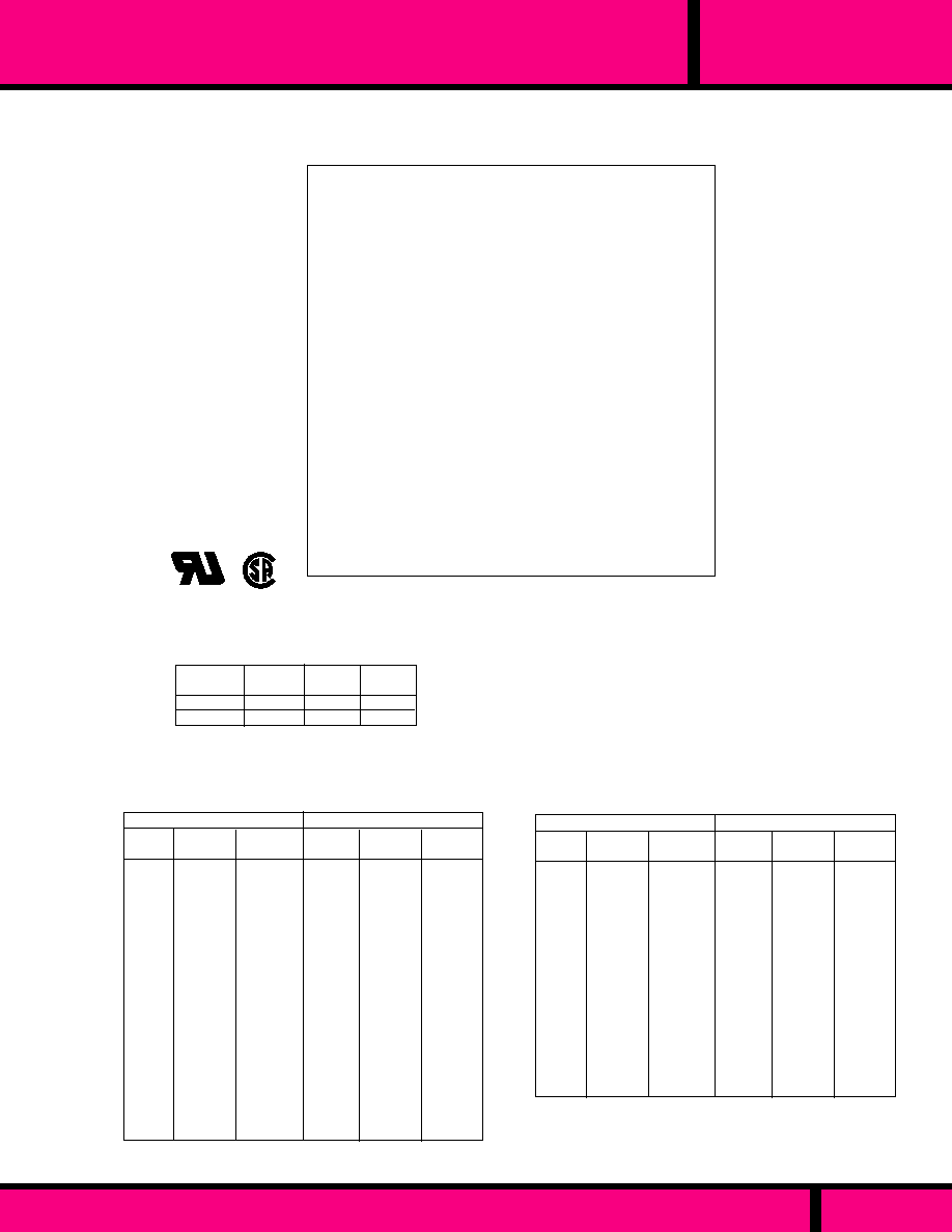
112, 112-PGF
2.34
2.80
3.25
4.40
5.50
6.90
9.10
10.8
13.1
20.6
26.5
30.0
35.0
45.5
49.0
72.0
95.0
122
146
190
230
Minimum
Voltage
390
310
250
200
160
114
910
83.0
69.0
50.0
42.0
35.0
26.0
22.0
16.4
13.0
10.2
8.5
6.5
4.9
4.9
6
9
13
22
34
60
100
130
190
370
630
860
1,350
2,070
3,000
6,500
9,230
14,300
22,500
38,500
53,000
0.18
0.22
0.27
0.34
0.41
0.55
0.68
0.86
1.09
1.37
1.72
2.11
2.77
3.46
4.33
5.47
7.11
8.53
10.8
14.1
17.7
323
260
211
165
133
95.0
76.0
69.0
57.0
42.0
35.0
29.0
22.0
18.0
14.0
11.0
8.5
7.0
5.5
4.0
3.5
0.55
0.84
1.26
2.10
3.10
5.80
9.00
12.5
19.0
33.0
50.0
74.0
1219
197
312
504
840
1,220
1,990
3,450
5,050
DC COILS
AC COILS, 50/60 HZ
COIL SPECIFICATIONS
Measured @ 25�C
Minimum
Voltage
Minimum
Milliamps
Impedance
Ohms
Minimum
Voltage
Resistance
Ohms
AC COILS, 50/60 HZ
DC COILS
LOAD
AC
DC
2A
-
240VAC
CONTACT RATINGS
Min. Voltage:
Min. Current:
Series Coils:
SERIES
2 AMP, LOW COIL POWER, 1 & 2 POLE PLUG-IN
PAGE 188
WEBSITE: www.magnecraft.com EMAIL:info@magnecraft.com FAX ON DEMAND 1-800/891-2957, DOCUMENT 100
Selected from coil tables
Selected from coil tables
Available for connection in
series with loads up to 50
Amps for series 112, and
10 Amps for series 112-PGF.
OPERATING DATA: (All Types)
TYPES 112XBX, 112XBXPGF
TYPES A112XAX, 112XAXPGF
177
143
116
91.0
74.0
52.5
41.5
38.0
31.5
23.0
19.0
15.7
11.8
9.65
7.65
6.00
4.66
3.85
2.98
2.25
1.93
1.53
1.22
0.95
0.74
6
9
13
22
34
60
100
130
190
370
630
860
1,350
2,070
3,000
6,500
9,230
14,300
22,500
38,500
53,000
85,000
120,600
177,000
300,000
1.0
1.4
1.6
2.0
2.5
3.5
4.3
5.0
6.0
8.5
12.0
13.5
16.
20
23
33
43
55
67
87
103
130
146
168
225
0.55
0.84
1.26
2.10
3.10
5.80
9.00
12.5
19.0
33.0
50.0
74.0
129
197
312
504
840
1,220
1,990
3,450
5,050
7,700
11,700
19,000
34,000
0.08
0.10
0.12
0.15
0.19
0.25
0.30
0.39
0.49
0.62
0.78
0.95
1.30
1.60
2.00
2.50
3.20
3.90
4.80
6.40
8.00
9.70
11.7
16.0
21.0
Minimum
Milliamps
145
117
95.0
73.0
60.0
43.0
33.0
31.0
26.0
18.8
15.5
12.8
9.70
7.90
6.30
4.90
3.80
3.15
2.43
1.84
1.58
1.25
1.00
0.84
0.61
Minimum
Milliamps
Resistance
Ohms
Impedance
Ohms
Minimum
Milliamps
Minimum
Voltage
30VDC
2A
2A
2A
0.25A
120VAC
Approvals for
A112XAX & XBX Only.
UL Recognized
File No. E7104
COIL
Overvoltage, max.
CONTACTS
Contact Material:
TIMING
Operate Time:
Release Time:
DIELECTRIC STRENGTH
Across open contacts:
All Mutually Insulated
current carrying parts to
ground:
TEMPERATURE
Rated Operation:
LIFE EXPECTANCY
Mechanical:
Electrical:
MISCELLANEOUS
Enclosure:
Weight:
AC, 5 x min. voltage,
DC, 10 x min. voltage (up to 300V)
Fine Silver
20 mS Max. @ Nominal Voltage.
20 mS Max. @ Nominal Voltage.
500 V rms
1500 V rms
-45�C to +65�C
500,000 Operations no load
100,000 Operations @ Rated Load.
Clear polycarbonate. (112-PGF Only)
7.05 oz. (200 g) approx.
GENERAL SPECIFICATIONS 112, 112-PGF

PAGE 189
WEBSITE: www.magnecraft.com EMAIL:info@magnecraft.com FAX ON DEMAND 1-800/891-2957, DOCUMENT 100
67S
CLASS
3 AMP, LOW COIL POWER, 2 & 4 POLE PLUG-IN
3 AMPS
3 AMPS
3 AMPS
3 AMPS
3 AMPS
3 AMPS
85mW
100mW
100mW
200mW
200mW
200mW
NOMINAL INPUT
MILLIAMPS DC
CONTACT
RATING
PULL-IN
MILLIAMPS DC
PULL-IN
WATTS
NOMINAL
RESISTANCE
(OHMS)
9.4 mADC
6.4 mADC
4.5 mADC
13.7 mADC
9.1 mADC
6.5 mADC
1000
2500
5000
1000
2500
5000
9.2 mADC
6.3 mADC
4.4 mADC
13.5 mADC
8.9 mADC
6.3 mADC
DPDT
DPDT
DPDT
4PDT
4PDT
4PDT
CLASS 67 - DC OPERATED - ULTRA SENSITIVE - PLUG-IN STYLE WITH 3-48 UNC STUD.
STANDARD CONTACTS
W67SCSX-1
W67SCSX-2
W67SCSX-3
W67SCSX-6
W67SCSX-7
W67SCSX-8
PART NUMBERS
CROSS REFERENCE
TO
POTTER & BRUMFIELD
CONTACT
CONFIGU-
RATION
R10SE1(X or Y)2-J1.0K
R10SE1(X or Y)2-J2.5K
R10SE1(X or Y)2-J5.0K
R10SE1(X or Y)4-J1.0K
R10SE1(X or Y)4-J2.5K
R10SE1(X or Y)4-J5.0K
Part numbers shown also available thru Stocking Distribution.
COIL
Pickup voltage:
Dropout voltage:
Coil resistance:
Maximum coil dissipation:
Coil Temperature rise:
Maximum coil temperature:
CONTACTS
Contact material:
Contact resistance:
CAPACITANCE
Between contacts:
Contact to coil:
Coil to frame:
80% of nominal voltage or less.
10% of nominal or more.
�
10% measured @ 25�C
2.2 watts @ 25�C
30�C per watt
105�C
Silver, Gold overlay
50 milliohms max. initial
2 pf, typ.
2 pf, typ.
30 pf, typ.
DIELECTRIC STRENGTH
Contact to coil:
Across open contacts:
Coil to frame:
Contacts to frame:
Insulation resistance:
TEMPERATURE
Operating:
Storage:
MISCELLANEOUS
Enclosure Material:
Operating Position:
Mounting:
Weight:
1500 V rms
500 V rms
1000 V rms
1500 V rms
1000 megohms @ 25�C & 50% R.H.
-55�C to + 70�C
-55�C to +105�C
Polycarbonate see thru plastic cover.
Any
Socket or 3-48 UNC stud
0.77 to 1.4 oz. (22 to 40 grams)
.170
(4.3)
Elongated Hole .100 x .040 ( 2 x .1)
"A"
1.20 Max.
(30.3)
.200 Max.
(5.1)
3-48UNC-2A Thd.
.094
(2.3)
Tolerances
�
.010 Inches
All Contact Terminals are .010 Thick
all coil terminals are .018 Thick.
CONTACT
CONFIGU-
RATION
"A"
DIM.
.978
(24.8)
1.156
(29.4)
DPDT
4PDT
DIMENSIONS
UL RECOGNIZED
FILE NO. E52197
COIL
Measured @ 25�C
SEE SECTION 10 FOR MATING SOCKETS
Load
Current
Load
Voltage
Number of Operations
Ultra
sensitive
1.0A
0.5A
0.1A
1mA
28VDC/120VAC
28VDC/120VAC
6 VDC
6 VDC
5 X 10
5
5 X 10
6
5 X 10
7
5 X 10
7
-
TYPICAL CONTACT LIFE EXPECTANCY FOR
SWITCHING RESISTIVE LOADS @ 25�C
4
PDT
.014
.008
POLES
OPERATE TIME
RELEASE TIME
DPDT
012
.008
CLASS 67 TYPICAL TIMING VALUES
Measured at Nominal Voltage @ 25�C
SPECIFICATIONS CLASS 67S
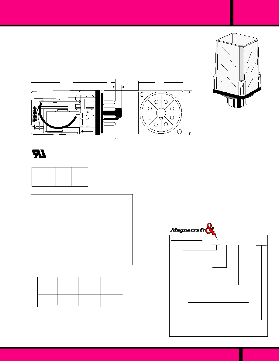
SENSITIVE PLUG-IN, 5 AMP, 1 - 3 POLES
392
SERIES
Series
Series 392 enclosed plug-in, low
power consumtion coil.
Open Style (Consult Factory)
Contact Arrangements
XAX- SPDT
XBX - DPDT
XCX - 3PDT
Construction Style
Open Style: ( Consult Factory for
mounting styles, special wiring etc.).
Enclosed Plug-in - CODE 48P
Options
Indicator Lamp, (125 VDC coil only.see coil
specifications) - CODE L
Manual Actuator - CODE M
Operating Current (DC Only)
XAX: 11.1, 7.0, 5.0, 3.5 (Add M)
XBX: 15.8, 10.0, 7.0, 5.0 (Add M)
XCX: 19.3, 12.0, 8.5, 6.0 (Add M)
ORDERING CODE
Typical Type No.
392 XBX 48P LM - 5.0M
Struthers-Dunn
SEE SECTION 10 FOR MATING SOCKETS
The 392 series relay has been designed to operate at 125 Milliwatts
per pole. Because of the coil sensitivity, the contacts are rated at 5 Amps.
The Industry standard 8 pin octal plug is used with SPDT & DPDT contact
configurations, and the 11 pin plug is used with 3PDT contact configurations.
Silver contacts are standard on this 5 Amp Relay.
1.37
(34.9)
.40
(10.1)
.675
(17.1)
2.25
(57.1)
1
5
2
6
3
7
4
8
1.37
(34.9)
OUTLINE DIMENSIONS
Dimensions are shown in INCHES and (MILLIMETERS).
CONTACTS
Contact Material:
TIMING
Operate Time:
Release Time:
DIELECTRIC STRENGTH
Across open contacts:
All Mutually Insulated current
carrying parts to ground:
Insulation Resistance:
TEMPERATURE
Rated Operation:
LIFE EXPECTANCY
Mechanical:
Electrical:
MISCELLANEOUS
Enclosure:
Weight;
Resistance
(Ohms)
11.1
7.0
5.0
3.5
1,000
2,500
5,000
10,000
15-44
23-68
32-97
45-139
SPDT
392XAX
mA Volts
15.8
10.0
7.0
5.0
21-44
32-68
45-97
64-139
19.3
12.0
8.5
6.0
25-44
39-68
55-97
77-139
COIL SPECIFICATIONS @ 25�C
Silver
20 mS Max. @ Nominal Voltage.
15 mS Max. @ Nominal Voltage.
500 V rms
1500 V rms
1000 Megohms min. 500 V
-45�C to +70�C
10 Million Operations no load
100,000 Operations @ Rated Load.
Clear polycarbonate
3-1/2 oz. (99.2 g approx.).
3PDT
392XCX
mA Volts
DPDT
392XBX
mA Volts
NOTES:
(1) Rates for continuous operation at 25�C at voltages
within listed ranges.
(2) Must operate at min. currents listed. Specify current
when ordering
POWER CONSUMPTION:
Resistive
5A
5A
120VAC
30VDC
LOAD
CONTACT RATINGS
UL Recognized
File No. E13224
3
PDT
D
PDT
SPDT
WIRING DIAGRAM
VIEWED FROM PIN END
125mW per pole @ currents
listed in the coil table.
PAGE 190
WEBSITE: www.magnecraft.com EMAIL:info@magnecraft.com FAX ON DEMAND 1-800/891-2957, DOCUMENT 100
GENERAL SPECIFICATIONS 392

Series
Series 292 , 3-Way Terminals
125 Milliwatts per pole.
Contact Arrangements
XAX- SPDT (1 Form C)
XBX - DPDT (2 Form C)
XCX - 3PDT ( 2 Form C)
Construction Style
Open Style ( Consult Factory for
mounting styles, special wiring etc.)
Enclosed Plug-in - CODE C
Enclosed Bracket Mount - CODE C1
Enclosed with 6-32 Side tapped hole- CODE C2
Enclosed Bracket Mount - CODE C!
Enclosed with 6-32 side stud - CODE CS2
Options
Gold Diffused Contacts - CODE G
Indicator Lamp (125VDC Only) -CODE L
Manual Actuator - CODE M
Printed Circuit Terminals - CODE T
Coil Current (DC Milliamps Only).
XAX: 11.1, 7.0, 5.0, 3.5 (Add M)
XBX: 15.8, 10.0, 7.0, 5.0 (Add mA)
XCX: 19.3, 12.0, 8.5, 6.0 (Add mA)
ORDERING CODE
Typical Type No.
292 XBX CS1 L - 10D
SEE SECTION 10 FOR MATING SOCKETS
CONTACT RATINGS
Resistive
5A
5A
120VAC
30VDC
LOAD
5A
240VAC
NOTES:
(1) Rates for continuous operation at 25�C at voltages
within listed ranges.
(2) Must operate at min. currents listed. Specify current
when ordering
POWER CONSUMPTION: 125mW per pole @ currents
listed in the coil table.
Resistance
(Ohms)
11.1
7.0
5.0
3.5
1,000
2,500
5,000
10,000
15-44
23-68
32-97
45-139
SPDT
392XACX
mA Volts
15.8
10.0
7.0
5.0
21-44
32-68
45-97
64-139
DPDT
392XBX
mA Volts
19.3
12.0
8.5
6.0
25-44
39-68
55-97
77-139
3PDT
392XCX
mA Volts
COIL SPECIFICATIONS @ 25�C
CONTACTS
Contact Material:
TIMING
Operate Time:
Release Time:
DIELECTRIC STRENGTH
Across open contacts:
All Mutually Insulated current
carrying parts to ground:
Insulation Resistance:
TEMPERATURE
Rated Operation:
LIFE EXPECTANCY
Mechanical:
Electrical:
MISCELLANEOUS
Enclosure:
Weight:
Silver
20 mS Max. @ Nominal Voltage.
15 mS Max. @ Nominal Voltage.
500 V rms
1500 V rms
1000 Megohms min. 500 V
-45�C to +70�C
10 Million Operations no load
100,000 Operations @ Rated Load.
Clear polycarbonate.
3 oz. (85.05 g) approx..
GENERAL SPECIFICATIONS
Struthers-Dunn
SENSITIVE , 3-WAY TERMINALS, 5 AMP, 1 - 3 POLES
SERIES
292
PAGE 191
WEBSITE: www.magnecraft.com EMAIL:info@magnecraft.com FAX ON DEMAND 1-800/891-2957, DOCUMENT 100
UL Recognized
File No. E13224
R
ENCLOSED BRACKET MOUNT
The Body dimensions for the
Enclosed style Plug-in are the
same as the Bracket Mount style.
Manual Push Button
Actuator
4
1
2
3
6
5
A
B
8
9
7
1.90Max.
(48.4)
1.40Max.
(35.5)
.28 Typ.
(7.1)
.625 Typ.
(15.8)
.156
(3.9)
2.90Max.
(73.8)
2.50
(63.5)
.218
(5.56)
.187 x .020
(4.76 x 0.51)
QC Terminals Typical
1.53 Max.
(38.8)
Top mount plate
& Stud
- OR -
ENCLOSED STYLE
Choice of 6-32 Stud or Tapped Core
with anti-rotation tab.
6-32 Stud with top mounting plate and
1/8" nominal length anti rotation tab.
3
6
7
9
4
8
5
2
1
A
B
DPDT
3
6
7
9
4
8
5
2
1
A
B
SPDT
292XAX
292XBX
3
6
7
9
4
8
5
2
1
A
B
3PDT
Viewed from terminal end
WIRING DIAGRAM
292XCX
OUTLINE DIMENSIONS
Dimensions shown are in INCHES and (MILLIMETERS)
The 292 series relay has been designed to operate on 125 MILLIWATTS
per pole. Because of this coil sensitivity, the contacts are rated at 5 Amps. The
3-way terminal design provides additional versatility in wiring. The 1 to 3 Form
"C" contact configurations, are ideal for low current DC circuits that require up to
a 5 Amp outputs. Silver contacts are standard on this 5 Amp Relay.

10
SOCKETS
AND
ACCESS0RIES
S E C T I O N 10
Page 192

SOCKET SELECTION GUIDE
Magnecraft
Struthers-Dunn
70-464-1
70-465-1
Panel or
DIN
Mount
Octal base, 8 or 11 Pin
socket. Panel or DIN rail
mount with Screw
Terminals & pressure
plates. Fits all standard
8 & 11 pin octal plugs.
Screw
Screw
1, 2
3
250
314
8
11
8
14
8
14
8
14
Screw
Screw
Solder
Solder
P.C.
P.C.
Screw
1
2
5
8
Panel or
Din rail
Class 76
Panel or DIN mount
Socket. Screw
Terminals with
pressure plates
70-478-1
70-475-1
219 Style
Front connected wiring on
one level with Screw
Terminals. Mating relays
have Locking Clip that
mates with clip receiver
in socket. All Sockets are
supplied with insulated
backing plate. Fits 14 pin
219 style relays.
14
219
14 Pin
Versions
219
T219
246, 247
B255,
A311
349,
112-PGF
RSX1800
101-112
RRX164
2 to 5
Pole
12
219 Style
Front connected wiring on
one level with Screw
Terminals. Mating relays
have Locking Clip that
mates with clip receiver
in socket. All Sockets are
supplied with insulated
backing plate. Fits 12 pin
219 style relays.
27390
Chassis
Chassis
P.C.
P.C.
70-124-1
70-124-2
70-178-1
70-178-2
1, 2
or 3
Class 388 & 283
Square Base Socket for
blade style relays. Solder/
Plug-in, Quick connect or
Printed Circuit terminals.
P.C. Socket without
mounting ears 70-178-2
235,
236,
388
Screw
1, 2
3
1, 2
4
1, 2
4
1, 2
4
Panel or
DIN Mt.
Panel or
DIN Mt.
Chassis
Chassis
P.C.
P.C.
70-459-1
70-461-1
70-401-1
70-378-1
70-402-1
70-379-1
70-463-1
Class 388 & 283
Square Base 11 pin
Panel/DIN rail Mount,
with Screw Terminals.
Class 78
Panel Mount/DIN rail
mount with screw
Terminals, Chassis
mount with solder
terminals or P.C. mount
for direct solder to P.C.
board.
11
11
235, 236,
or 388,
Solder,
3/16" Q.C.
PC
P.C.
Panel
Screw
2 to 6
Pole
Panel
Screw
33377
76EU
FEATURES
SOCKET
PART
NO.
NO.
OF
PINS
USE
SOCKET
WITH
RELAY
NO. OF
POLES
MOUNT-
ING
HOLD-
DOWN
CLIP
INCLUDED
78R
78
78R
78
78R
78
PAGE 193
WEBSITE: www.magnecraft.com EMAIL:info@magnecraft.com FAX ON DEMAND 1-800/891-2957, DOCUMENT 100
TERMINAL
TYPES
None
None
Yes Yes Yes
16-1197
16-1197
16-1197
16-1197
16-1197
16-1197
Yes Yes Yes
No
No
No
No
No
16-1278
or
16-1239
Long Body
Yes Yes Yes
16-722-2
16-722-2
16-722-2
16-722-2
Yes Yes Yes
Yes Yes Yes
Yes Yes Yes
Yes Yes Yes
16-1264
No
No
No
No
No
No
Yes Yes Yes
Yes Yes Yes
Yes Yes Yes
Yes Yes Yes
Yes Yes Yes
Not
Required
Yes Yes Yes
No
None
No
Yes
Yes
None
No
Yes Yes
CLIP
PART
NO.
APPROVALS:
UL CSA CE
Panel or
DIN
Mount
PAGE
NO.
195
196
197
198
199
200
201
201
202

SOCKET SELECTION GUIDE
Magnecraft
Struthers-Dunn
CX-4092
DIN Rail
No
DIN rail conversion
kit for use on series
219 style sockets.
27390 (12 pin) and
33377 (14 pin)
67
10
10
16
16
22
22
28
28
2
2
4
4
6
6
8
8
Solder
P.C.
Solder
P.C.
Solder
P.C.
Solder
P.C.
Chassis
P.C.
Chassis
P.C.
Chassis
P.C.
Chassis
P.C.
70-303-1
70-304-1
70-305-1
70-306-1
70-307-1
70-308-1
70-309-1
70-310-1
FEATURES
Solder
2
10
97
Class 97
Chassis Mount
Socket with metal
mounting flange.
70-312
DIP
14
1 or 2
P.C.
P.C.
DIP
P.C. style 14 Pin
Socket. Fits 0.100
board spacing.
70-276
ACCESSORIES
No
No
Yes
Yes
Yes
Yes
Yes
Yes
Yes
Yes
16-875-1
16-875-1
16-875-2
16-875-2
16-875-3
16-875-3
16-1120-8
16-1120-8
APPROVALS:
UL CSA CE
CLIP
PART
NO.
HOLD-
DOWN
CLIP
INCLUDED
MOUNT-
ING
TERMINAL
TYPES
NO. OF
POLES
USE
SOCKET
WITH
RELAY
NO.
OF
PINS
SOCKET
PART
NO.
No
No
No
No
No
No
No
No
No
No
No
No
No
No
No
No
No
No
No
No
No
No
No
No
No
None
No
No
No
No
No
Chassis
None
No
No
Class 67
Chassis Mount Socket
has Solder terminals.
Printed Circuit Socket
pins are soldered
directly to the P.C.Board.
All sockets have relay
grounding strip that
connects to stud on
plug-in style relays.
203
204
PAGE
NO.
205
205
PAGE 194
WEBSITE: www.magnecraft.com EMAIL:info@magnecraft.com FAX ON DEMAND 1-800/891-2957, DOCUMENT 100
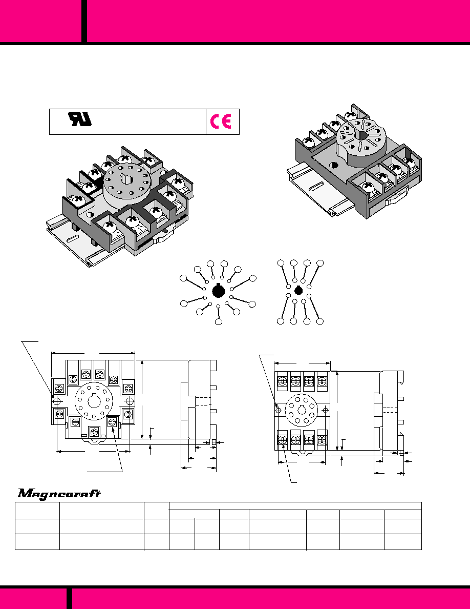
8 or 11 PIN SCREW TERMINAL SOCKETS
OCTAL
PAGE 195
WEBSITE: www.magnecraft.com EMAIL:info@magnecraft.com FAX ON DEMAND 1-800/891-2957, DOCUMENT 100
.165 Dia. Mounting Hole
(2 Places)
1.29
(32.7)
2.020
(51.3)
.830
(21.08)
.150
(3.6)
.125 - .156
(3.17 - 3.96)
1.60 Max.
(40.6)
.610
(15.5)
Part Numbers shown also available thru Stocking Distribution
PART NUMBERS
70-464-1
70-465-1
8 Pin Octal Socket, Panel/DIN
mount, Screw Terminals
11 Pin Octal Socket, Panel/DIN
mount,, Screw Terminals
STYLE
23.8
75
Cross Reference reflects compatibility with relay foot prints. Shape, mounting, method of relay hold down, and socket internal wiring can vary.
* Track mountable but not compatible with Magnecraft mounting hole locations.
P&B
27E122
27E123
IDEC
CUSTOM CONNECTOR
OT08-PC
OT11-PC
PF083A-E
PF113A-E*
OMRON
ALLEN-BRADLEY GRAINGER
700-HN125
700-HN126
5X852
6X156*
CROSS REFERENCE
SR2P-06
SR3P-06*
27E891
27E892*
WEIGHT
(GRAMS)
6-32 x .312 Combination
Head Screw & Pressure
Clamp (11 Places)
Tolerances:
�
.010
�
(0.25)
Unless otherwise shown.
2.33
(59.1)
2.06
(52.3)
.165 Dia. Mounting Hole
(2 Places)
2.05
(52.07)
.125 - .156
(3.17 - 3.96)
6-32 x .312 Combination
Head Screw & Pressure
Clamp (11 Places)
.150
(3.6)
.580
(14.73)
.970
(24.6)
.770
(19.56)
Tolerances:
�
.010
�
(0.25)
Unless otherwise shown.
DIN RAIL
2
3
4
5
1
6
7
8
9
10
11
1
2
3
4
5
6
7
8
WIRING DIAGRAMS
70-465-1 PANEL/DIN MOUNT SOCKET
Struthers-Dunn Equivalent Part Number 75225
Dimensions shown in Inches and (Millimeters)
OUTLINE DIMENSIONS
SPDT, DPDT
3PDT
Compatible with European 35 mm DIN rail mounting.
Time saving snap in installation.
Non metallic spring mechanism eliminates mounting hardware.
Pressure clamp screw terminals hold wires mechanically secure.
Pressure clamp terminals provide excellent electrical connection.
Terminals accept up to two # 12 AWG wires.
One piece stamped metal interconnections. No welded or soldered
connections.
Fits all standard 8 and 11 pin relay plugs.
Can also be surface mounted with 2 screws.
DESIGNED FOR PANEL OR DIN MOUNT
RATED: 10 AMPS, 300V
MOLDED BASE, BREAK RESISTANT BLACK
THERMOPLASTIC WITH CLOSED BACK.
Recognized to Canadian safety
requirements under the Component
Recognition Program of Underwriters
Laboratories Inc.
US
C
E70550
70-464-1 PANEL/DIN MOUNT SOCKET
Struthers-Dunn Equivalent Part Number 75224
DIN RAIL

SCREW TERMINAL SOCKETS - 1, 2 & 4 POLE
78
CLASS
PAGE 196
WEBSITE: www.magnecraft.com EMAIL:info@magnecraft.com FAX ON DEMAND 1-800/891-2957, DOCUMENT 100
DIN RAIL
SPDT, DPDT
1
2
3
4
5
6
7
8
WIRING DIAGRAMS
4PDT
1
2
3
4
5
6
7
8
9
10
11
13
14
12
70-461-1 PANEL/DIN MOUNT SOCKET
16-1197 Spring Clip Ordered separately.
Struthers-Dunn Equivalent Part Number 75228
70-459-1 PANEL/DIN MOUNT SOCKET
16-1197 Spring Clip Ordered separately.
Struthers-Dunn Equivalent Part Number 75227
.170
(4.3)
.240
(6.10)
Typ.
2.550
(64.8)
1.275
(32.4)
.895
(22.7)
.785
(19.9)
1.015
(25.78)
.197
�
.015
(5.0
�
0.4)
1.210
(30.7)
Dimensions shown in Inches and (Millimeters)
OUTLINE DIMENSIONS
Tolerances:
�
.010
�
(0.25)
Unless otherwise shown.
1.18
(30)
1.02
(26)
.315
(8.0)
2.65
(67.3)
1.325
(33.6)
1.00
(2.54)
1.080
(27.4)
.160
(4.0)
.156
(4.0)
.800
(20.3)
Tolerances:
�
.010
�
(0.25)
Unless otherwise shown.
DIN RAIL
PART NUMBERS SHOWN ALSO AVAILABLE THRU STOCKING DISTRIBUTION.
NO. OF
POLES
PART
NUMBERS
Screw Terminal
Screw terminal
70-459-1
70-461-1
1 or 2
4
Cross Reference reflects compatibility with relay foot prints. Shape, mounting, method of relay hold down,
and socket internal wiring can vary.
* Panel mount
** Panel mount with grounding screw.
27E895
27E894
P&B
P&B
SH2B-05
SY4S-05
IDEC
CUSTOM CONNECTOR
GT08-15
MT14-PC
PTF08A-E
PYF14A-E
OMRON
700-HN116
700-HN128
ALLEN-BRADLEY
CROSS REFERENCE
2A582
2A584
GRAINGER
27E487*
27E166**
SOCKET STYLE
WEIGHT
(GRAMS)
49.8
42.8
DESIGNED FOR PANEL OR DIN MOUNT
4 POLE: RATED 7 AMPS @ 300 VOLTS
1 & 2 POLE: RATED 10 AMPS @ 300 VOLTS
Compatible with European 35 mm DIN rail mounting.
Time saving snap in installation.
Non metallic spring mechanism eliminates mounting hardware.
Pressure clamp screw terminals hold wires mechanically secure.
Pressure clamp terminals provide excellent electrical connection.
Terminals accept up to two # 14 AWG wires for the 70-461-1,
and up to #12 AWG wires for the 70-459-1 sockets.
One piece stamped metal interconnections. No welded or soldered
connections.
Can also be surface mounted with 2 screws.
Recognized to Canadian safety
requirements under the Component
Recognition Program of Underwriters
Laboratories Inc.
US
C
E70550

78
CLASS
CHASSIS MOUNT SOCKETS - 1, 2 & 4 POLE
Recognized to Canadian safety
requirements under the Component
Recognition Program of Underwriters
Laboratories Inc.
US
C
E70550
Sockets fit Class 78 style relays. The sockets are chassis
mounted and snap into panels up to .0625 (1.56) thick.
The 4 pole socket has an additional receptacle and solder
terminal for grounding 4 pole relays.
SOLDER TERMINALS
SNAPS INTO CHASSIS
4 POLE: RATED 5 AMPS @ 300 VOLTS
1 & 2 POLE: RATED 10 AMPS @ 300 VOLTS
RECOMMENDED
PANEL CUTOUT
.148 x .014
(3.75 x 0.355)
.850
(21.59)
1.150
(29.21)
.750
(19.05)
.623
(15.82) Ground lug
1.015
(25.78)
.860
(21.84)
.105
(2.67)
.075
(1.90)
1.158
�
.010
(29.41)
.860
(21.8)
.075
(1.90)
.180
(4.57) Typ.
RECOMMENDED
PANEL CUTOUT
1.015
(25.8)
.440
(11.18)
.770
(19.56)
.844
(21.44)
Tolerances:
�
.010
�
(0.25)
Unless otherwise shown.
70-401-1 SOLDER TERMINAL SOCKET
16-1197 Spring Clip Ordered separately.
Dimensions shown in Inches and (Millimeters)
OUTLINE DIMENSIONS
Struthers-Dunn Equivalent Part Number 40051
NO. OF
POLES
1 or 2
4
PART
NUMBERS
SOCKET STYLE
Solder Terminal
Solder Terminal
70-401-1
70-378-1
CUSTOM CONNECTOR
27E488
27E006
SH2B-51
SY4S-51
GR108-SLD
MR14-SLD
P&B
IDEC
6.5
6.2
PART NUMBERS SHOWN ALSO AVAILABLE THRU STOCKING DISTRIBUTION.
Cross Reference reflects compatibility with relay foot prints. Shape, mounting, method of relay hold down, can vary.
PT08
PY14
OMRON
700-HN117
700-HN104
ALLEN-BRADLEY
CROSS REFERENCE
WEIGHT
(GRAMS)
SNAP FITS
INTO
CHASSIS
.0625 (1.56)
THICK
70-378-1 SOLDER TERMINAL SOCKET
16-1197 Spring Clip Ordered separately.
Struthers-Dunn Equivalent Part Number 32884
.072 x .140 typ.
(1.83 x 3.56)
PAGE 197
WEBSITE: www.magnecraft.com EMAIL:info@magnecraft.com FAX ON DEMAND 1-800/891-2957, DOCUMENT 100
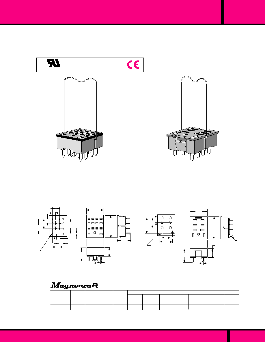
CLASS
78
P.C. TERMINAL SOCKETS - 2 & 4 POLE
78
CLASS
PRINTED CIRCUIT TERMINAL SOCKETS - 1, 2 & 4 POLE
PAGE 198
Recognized to Canadian safety
requirements under the Component
Recognition Program of Underwriters
Laboratories Inc.
US
C
E70550
Sockets fit Class 78 style relays. The sockets are manufactured
with "floating" (loose) P.C. terminals that allow the terminals to
aline with holes in the circuit board without binding or bending
to get correct fit and alignment of terminals. The 4 pole socket
has an additional receptacle and solder terminal for grounding
4 pole relays.
PRINTED CIRCUIT TERMINALS
4 POLE: RATED 5 AMPS @ 300 VOLTS
1 & 2 POLE: RATED 10 AMPS @ 300 VOLTS
WEBSITE: www.magnecraft.com EMAIL:info@magnecraft.com FAX ON DEMAND 1-800/891-2957, DOCUMENT 100
70-402-1
70-379-1
1 or 2
4
PART
NUMBERS
SOCKET STYLE
Printed Circuit
Printed Circuit
NO. OF
POLES
.850
(21.5)
.410
(10.4)
.660
(16.7)
.160
(4.06)
.350
(8.89)
.175
(4.45)
1.158
�
.010
(29.41)
.844
�
.010
(21.44)
.440
(11.18)
.620
(15.7)
.185
.417
(10.5)
70-379-1 SOLDER TERMINAL SOCKET
16-1197 Spring Clip Ordered separately.
Struthers-Dunn Equivalent Part Number 39830
70-402-1 SOLDER TERMINAL SOCKET
16-1197 Spring Clip Ordered separately.
Struthers-Dunn Equivalent Part Number 41463
PART NUMBERS SHOWN ALSO AVAILABLE THRU STOCKING DISTRIBUTION.
WEIGHT
(GRAMS)
5.8
5.9
27E489
27E031
P&B
SH2B-62
SY4S-61
IDEC
CUSTOM CONNECTOR
GR108-PCB
MR14-PCB
.078 Typ.
(1.98)
.672
(17.07)
.394
(10.0)
.672
(17.07)
.086 Dia.
(2.18)
.600
(15.24)
.060 Typ.
(1.52)
.623
(15.82)
Ground
Lug
.440
(11.18)
1.150
(29.21)
RECOMMENDED
PRINTED CIRCUIT LAYOUT
Viewed from component side
.140 x .014
(3.55 x 0.355)
.525
(13.34)
.070 Dia.
(1.78)
14 Places
.262
(6.67)
.145
(3.68)
.598
(15.19) .024
(0.61)
RECOMMENDED
PRINTED CIRCUIT LAYOUT
Viewed from component side
.175 x .010 typ.
(4.44 x .254)
Cross Reference reflects compatibility with relay foot prints. Shape, mounting and method of relay hold down can vary.
PT08-0
PY14
700-HN118
700-HN105
ALLEN-BRADLEY
2A583
-
GRAINGER
CROSS REFERENCE
Dimensions shown in Inches and (Millimeters)
OUTLINE DIMENSIONS
Tolerances:
�
.010
�
(0.25)
Unless otherwise shown.
OMRON
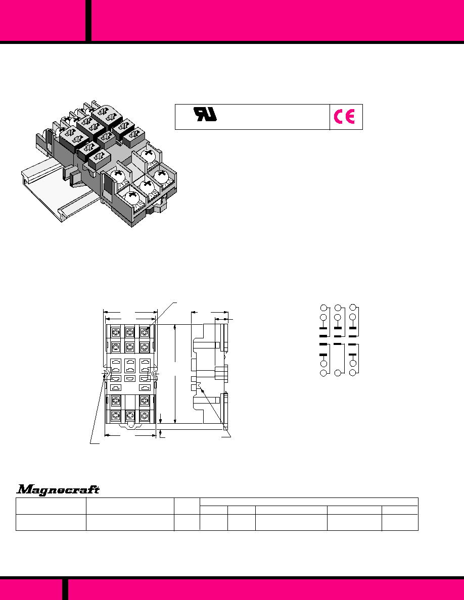
388 & 283
CLASS
SCREW TERMINAL SOCKET - 1, 2 & 3 POLE
Compatible with European 35 mm DIN rail mounting.
Time saving snap in installation.
Non metallic spring mechanism eliminates mounting hardware.
Pressure clamp screw terminals hold wire mechanically secure.
Pressure clamp terminals provide excellent electrical connection.
Terminals accept up to two # 12 AWG wires. Break resistant
thermoplastic. One piece stamped metal interconnections. No
welded or soldered connections.
Can also be surface mounted with 2 screws.
Recognized to Canadian safety
requirements under the Component
Recognition Program of Underwriters
Laboratories Inc.
US
C
E70550
FITS SQUARE BASE .187 (3/16")
BLADE STYLE RELAYS
RATED: 15 AMPS, 300 VAC
DIN RAIL
Struthers-Dunn Equivalent Part Number-75226
70-463-1 PANEL/DIN SOCKET
16-1278 Spring Clip Ordered separately.
STYLE
11 Pin, Panel/DIN rail mount,
with Screw Terminals
WEIGHT
(GRAMS)
50.6
27E893
P & B
IDEC
CUSTOM CONNECTOR
70-463-1 *
PART NUMBERS
SR3B-05
ALLEN-BRADLEY GRAINGER
CROSS REFERENCE
5X853
700-HN127
ST11-PC
Part Numbers shown also available thru Stocking Distribution
1.70
(43.1)
3.00
(76.2)
.150
(3.81)
1.03
(26.1)
.390
(9.9)
.150 Dia. (3.8)
(2 Places
Retaining notch for
hold down clip (2 Places)
DIMENSIONS ARE SHOWN IN INCHES AND (MILLIMETERS).
OUTLINE DIMENSIONS
Tolerances:
�
.010
�
(0.25)
Unless otherwise shown.
1.57
(39.9)
1.435
(36.4)
6-32 X .312 Combination Head
Screw and pressure clamp
6
5
4
3
2
1
B
A
WIRING DIAGRAM
TOP VIEW
9
8
7
* Order Part Number 16-1278 Hold Down Clip for relays with a case height of 1.90" using 3/16" (.187) terminals
Cross Reference reflects compatibility with relay foot prints. Shape, mounting, method of relay hold down, and socket internal wiring can vary.
PAGE 199
WEBSITE: www.magnecraft.com EMAIL:info@magnecraft.com FAX ON DEMAND 1-800/891-2957, DOCUMENT 100

SOLDER, Q.C. OR P.C. TERMINALS - 1, 2 & 3 POLE
388 & 283
CLASS
FITS SQUARE BASE .187 (3/16")
BLADE STYLE RELAYS
RATED: 15 AMPS, 300 VAC
1.37
(34.8)
.297
(7.5)
1.50
(38.1)
P.C. MOUNT
FIG. "B"
Printed Circuit
mounting
.156
(3.96)
.297
(7.5)
1.37
(34.8)
Printed Circuit mounting
with mounting Tabs
.875
(22.2)
.500 typ
(12.7)
.540
(13.72)
2.03
(51.6) 1.687
(42.85)
1.50
(38.1)
1.25
(31.75)
.125
(3.17)
.165 Dia.(4.19) 2 holes
.218
(5.54)
.130 Solder Terminal or
.187 (3/16" Q.C. Terminal
Connectors are
Brass, Tin Plated.
FIG. "A"
DIMENSIONS ARE SHOWN IN INCHES AND (MILLIMETERS).
OUTLINE DIMENSIONS
Tolerances:
�
.010
�
(0.25)
Unless otherwise shown.
70-124-1
70-124-2
70-178-1
70-178-2
FIG "A"
FIG "A"
FIG "A"
FIG "B"
.130 SOLDER TERMINAL
3/16" (.187) QUICK CONNECT
PRINTED CIRCUIT, WITH TABS
PRINTED CIRCUIT, NO TABS
STYLE
WEIGHT
(GRAMS)
FIG
PART NUMBERS
P & B
12.1
12.1
9.4
9.4
27E043
27E067
27E304
-
SR3B-51
-
-
-
IDEC
CUSTOM CONNECTOR
CM11-SLD
CM11-QDC
CM11-PCB
CM11-PCB-1S
ALLEN-BRADLEY
-
700-HN107
-
-
-
5X854
-
-
CROSS REFERENCE
Order Part Number 16-722-2 Hold Down Clip (Struthers-Dunn Equivalent 37067) for relays with a case height of 1.90 (48.2)
Part Numbers shown also available thru Stocking Distribution
Cross Reference reflects compatibility with relay foot prints. Shape, mounting and method of relay hold down can vary.
GRAINGER
Struthers-Dunn Equivalent Part Numbers
36580 = 70-124-1
36581 = 70-124-2
36579 = 70-178-1
16-722-2 Spring Clip Ordered separately.
.156
(3.96)
.287
(7.54)
.829
(21.0)
.611
(15.5)
Note: Holes not required when
using Fig. "B" style socket
Drill 11 .078 (1.98)
dia.holes for P.C.
terminals
1.68
(42.7)
.391
(9.94)
.875
(22.2)
.437
(11.1)
BOTTOM VIEW
1.27
(32.3)
1.68
(42.7)
1.39
(35.4)
.875
(22.2)
.257
(6.53)
.205
(5.21)
RECOMMENDED CHASSIS CUTOUT
BOTTOM VIEW
.156 (3.96Dia. (2
holes)
Drill two .156 (3.96) dia.
holes for mounting Tabs.
RECOMMENDED PRINTED
CIRCUIT BOARD LAYOUT
Recognized to Canadian safety
requirements under the Component
Recognition Program of Underwriters
Laboratories Inc.
US
E70550
C
Sockets fit Class square base style relays with 3/16" (.187)
terminals. The quick connect, solder terminal and printed
circuit sockets have mounting tabs for mounting to panels
using two screws. The 70-178-2 Printed circuit socket has
no mounting tabs
PAGE 200
WEBSITE: www.magnecraft.com EMAIL:info@magnecraft.com FAX ON DEMAND 1-800/891-2957, DOCUMENT 100

SCREW TERMINAL SOCKETS
SERIES
219
Recognized to Canadian safety
requirements under the Component
Recognition Program of Underwriters
Laboratories Inc.
US
C
E13224
E70550
UL LISTED WHEN USED
WITH SERIES 219 RELAYS
These Industrial style sockets offer front-connected wiring
on one level with screw terminals accessible and numbered
for ease in installation, wiring and checkout. Sockets are
polarized. The mating relay has a locking clip that snaps into
the socket, eliminating any need for external holding
devices. All sockets are supplied with an insulating
paper back plate for greater dielectric strength.
12 and 14 PIN PANEL MOUNT SOCKETS
FIT ALL 219 STYLE RELAYS WITH
12 OR 14 PIN PLUGS.
RATED: 10 AMPS, 600 VAC
.687
(17.4)
6-32 screws
12 Places
.173 (4.39)
mounting Holes
2 Places
INSULATING PAPER BACK PLATE
2.18
(55.3)
.780
(19.8)
2.65
(67.3)
1.687
(42.84)
.484
(12.29)
.687
(17.4)
6-32 screws
14 Places
.173 (4.39)
mounting Holes
2 Places
.780
(19.8)
INSULATING PAPER BACK PLATE
3.10
(78.74)
1.687
(42.84)
.484
(12.29)
2.18
(55.3)
WEIGHT
(GRAMS)
STYLE
102
120
12 PIN SOCKET
14 PIN SOCKET
27390
33377
PART NUMBERS
CROSS REFERENCE
CUSTOM CONNECTOR
SD12-PC
SD14-PC
Struthers-Dunn
Part Number Shown also Available thru Stocking distribution
When Sockets are mounted end to end, the distance between adjacent mounting holes should be 1" minimum.
12 PIN SOCKET
14 PIN SOCKET
DIMENSIONS ARE SHOWN IN INCHES AND (MILLIMETERS).
OUTLINE DIMENSIONS
Tolerances:
�
.010
�
(0.25)
Unless otherwise shown.
Notes: Insulating Back Plate Included with Socket
27390 - 12 PIN PANEL MOUNT SOCKET
33377 - 14 PIN PANEL MOUNT SOCKET
PAGE 201
WEBSITE: www.magnecraft.com EMAIL:info@magnecraft.com FAX ON DEMAND 1-800/891-2957, DOCUMENT 100
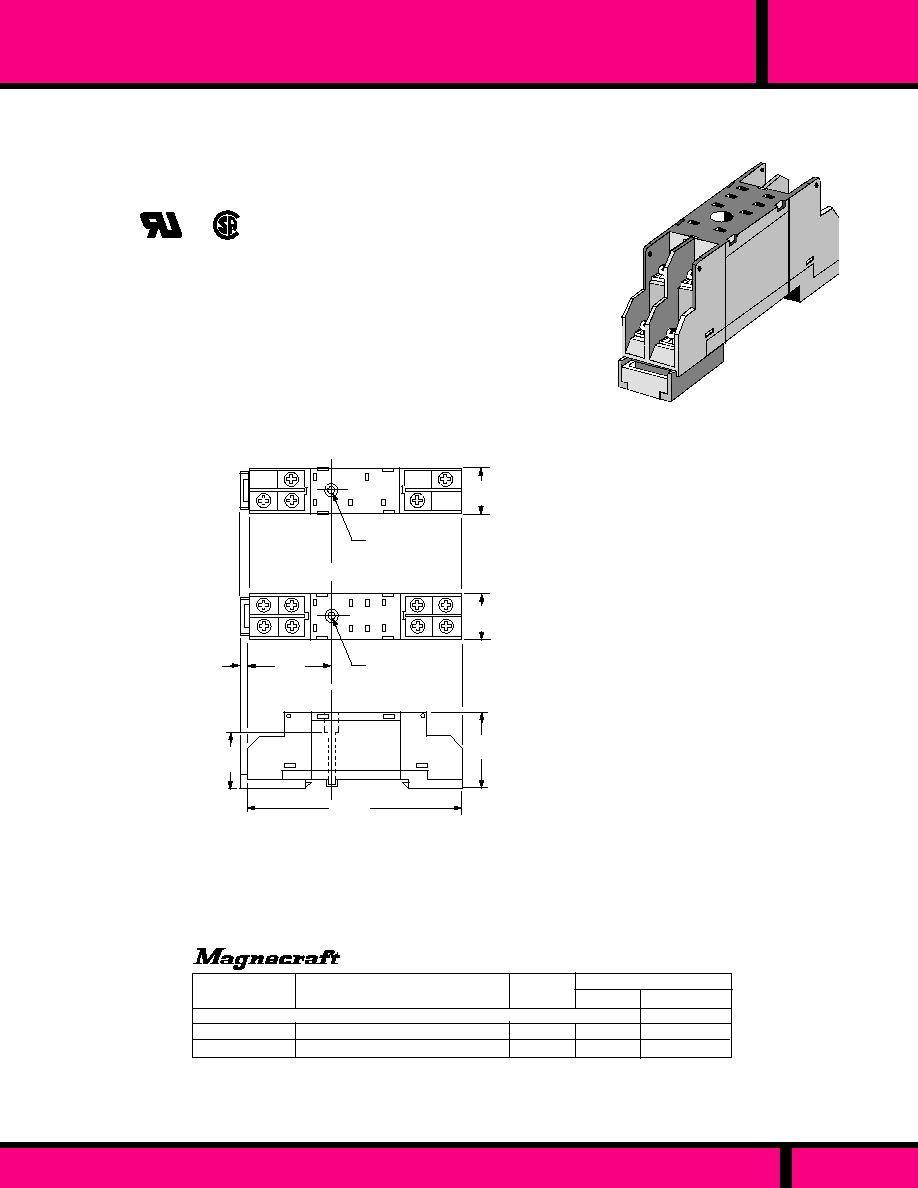
SCREW TERMINAL SOCKETS - 1 & 2 POLE
STANDARD FOOT PRINT FOR STYLE 76EURCPCX-
PART NUMBERS
WEIGHT
(GRAMS)
19.3
19.5
STYLE
SPDT, Panel/DIN mount, Screw Terminal
DPDT, Panel/DIN mount, Screw terminal
Part Numbers Shown also Available thru Stocking distribution
CROSS REFERENCE
27E1038
27E1039
Cross Reference reflects compatibility with relay foot prints. Shape, mounting, method of relay
hold down, and socket internal wiring can vary.
70-478-1
70-475-1
RP 78 604
RP 78 605
IDEC
P & B
76
CLASS
Compatible with European 35 mm DIN rail mounting.
Time saving snap in installation.
Pressure clamp screw terminals hold wires mechanically secure.
Pressure clamp terminals provide excellent electrical connection.
Terminals accept up to two # 14 AWG wires.
One piece stamped metal interconnections. No welded or soldered
connections.
Fits all standard Class 76 relays
Can also be surface mounted with 1 screw.
PANEL/DIN RAIL MOUNT.
DIELECTRIC STRENGTH 1500 V rms, 1 MINUTE.
RATED: 15 AMPS, 250 VAC.
70-475-1 PANEL/DIN SOCKET
16-1321 Spring Clip Ordered separately.
.75
(19)
SOCKET PART NO. (SPDT) 70-478-1
1.02
(26)
.153
(3.89)
1.25
(31.7)
2.765
(70.23)
.150 Dia.
(3.81)
.615
(15.6)
.615
(15.6)
SOCKET PART NO. (DPDT) 70-475-1
.150 Dia.
(3.81)
DIMENSIONS ARE SHOWN IN INCHES AND (MILLIMETERS).
OUTLINE DIMENSIONS
Tolerances:
�
.010
�
(0.25)
Unless otherwise shown.
PAGE 202
WEBSITE: www.magnecraft.com EMAIL:info@magnecraft.com FAX ON DEMAND 1-800/891-2957, DOCUMENT 100

SOLDER TERMINAL SOCKETS - 2 TO 8 POLE
2 POLE
.978
(24.8)
.350
(8.89)
.210
(5.33)
16-875-1 Spring hold down Clip included
.350
(8.89)
.210
(5.33)
1.390
(35.3)
6 POLE
16-875-3 Spring hold down Clip included
8 POLE
.350
(8.89)
.210
(5.33)
1.596
(40.54)
16-1120-8 Spring hold down Clip included
1.184
(30.1)
4 POLE
.350
(8.89)
.210
(5.33)
16-875-2 Spring hold down Clip included
NO. OF
POLES
2
4
6
8
Solder Terminal
Solder Terminal
Solder Terminal
Solder Terminal
PART NUMBERS SHOWN ALSO AVAILABLE THRU STOCKING DISTRIBUTION.
SOCKET STYLE
RELAY HOLD DOWN CLIP IS INCLUDED WITH ALL SOCKETS
PART
NUMBERS
WEIGHT
(GRAMS)
4.3
5.5
6.9
8.5
CROSS REFERENCE
POTTER-BRUMFIELD
27E125
27E126
27E127
27E211
GROUND STRIP FOR
3-48 UN-2A STUD
"B"
USE 3-48 SCREW &
NUT FOR MOUNTING
SOCKET
.750
(19.05)
.343 .562 .781 1.00
(8.71) (14.3) (19.84) (25.4)
SPDT
DPDT 4PDT 6PDT 8PDT
DIMENSION "B"
CHASSIS CUTOUT
.656
�
.015
(16.66)
�
0.38
.140
(3.5)
.109 DIA. (2.77)
.281
�
.015
(7.14)
�
0.38
.281
(7.14)
.354
(8.99)
CHASSIS CUTOUT
for panel mounting.
CHASSIS MOUNT
.350
(8.89)
.210
(5.33)
.090 X .045
(2.3 X 1.14)
Elongated Holes
70-303-1
70-307-1
70-309-1
70-305-1
70-303-1
70-305-1
70-307-1
70-309-1
OUTLINE DIMENSIONS
DIMENSIONS ARE SHOWN IN INCHES AND (MILLIMETERS).
Tolerances:
�
.010
�
(0.25)
Unless otherwise shown.
CLASS
67
Sockets fit Class 67 style relays with solder/plug-in
terminals. All sockets have an grounding strip that connects
with the mounting screw to the chassis. Contact material
used is spring brass, tin plated. The body material is
phenolic. Dielectric strength: 1000 V rms. Insulation
Resistance 10
9
megohms
CHASSIS MOUNT SOCKETS
RATED: 10 AMPS MAX.
PAGE 203
WEBSITE: www.magnecraft.com EMAIL:info@magnecraft.com FAX ON DEMAND 1-800/891-2957, DOCUMENT 100
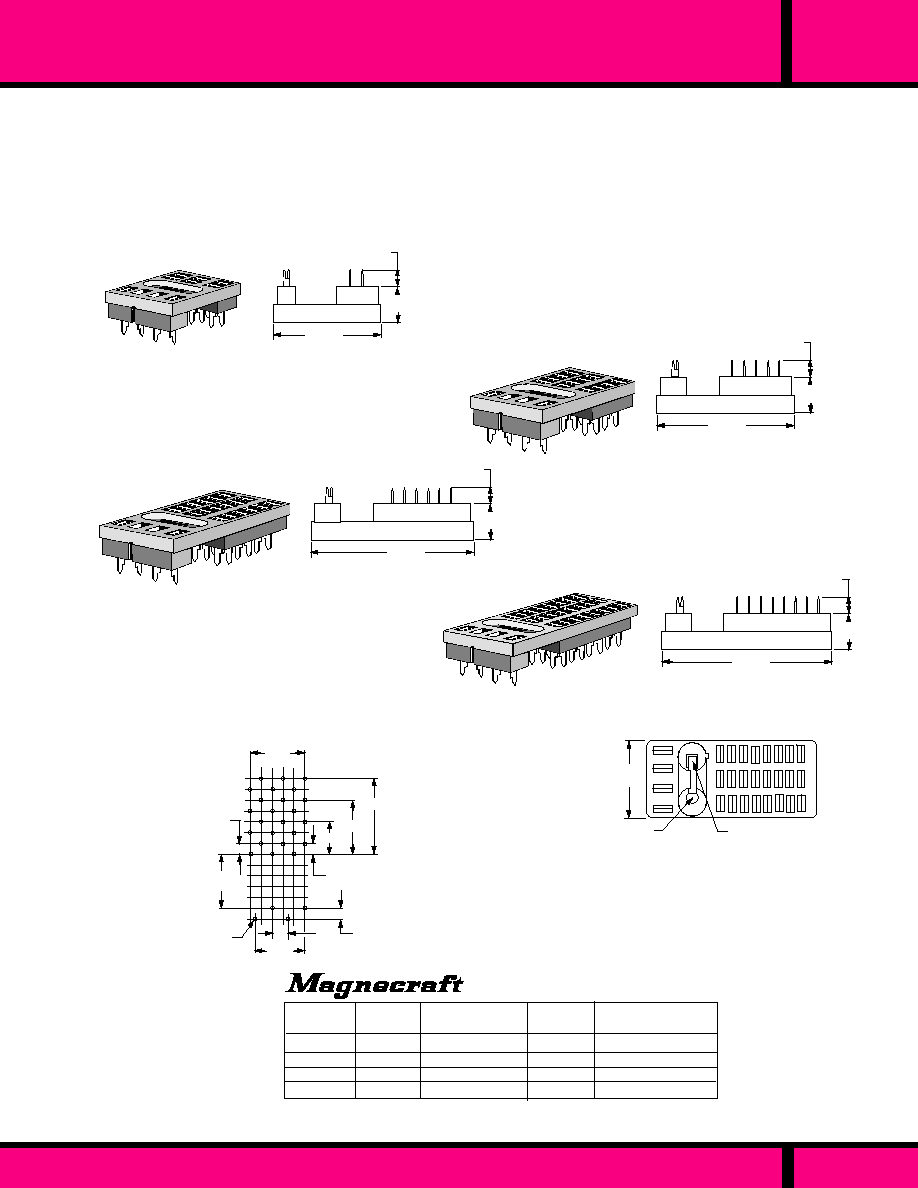
PAGE 204
WEBSITE: www.magnecraft.com EMAIL:info@magnecraft.com FAX ON DEMAND 1-800/891-2957, DOCUMENT 100
67
CLASS
P.C. TERMINAL SOCKETS - 2 TO 8 POLE
Sockets fit Class 67 style relays with solder/plug-in
terminals. All sockets have an grounding strip that connects
with the mounting screw to the chassis. Contact material
used is spring brass, tin plated. The body material is
phenolic. Dielectric strength: 1000 V rms. Insulation
Resistance 10
9
megohms
PRINTED CIRCUIT SOCKETS
RATED: 10 AMPS MAX.
NO. OF
POLES
SOCKET STYLE
2
4
6
8
P.C. Terminal
P.C. Terminal
P.C. Terminal
P.C. Terminal
PART
NUMBERS
.450
(11.43)
.150
(3.81)
.500
(12.7)
.500
(12.70)
2 Pole
4 Pole
6 Pole
8 Pole
.100
(2.54)
GRID
typical
.056 + .004 Dia.
- .000 Holes
(1.42 + .10)
- .00
.100
(2.54)
2 POLE
.180
(457)
.350
(8.89)
16-875-1 Spring hold down Clip included
4 POLE
.180
(457)
.350
(8.89)
16-875-2 Spring hold down Clip included
.350
(18.9)
6 POLE
.180
(4.57)
16-875-3 Spring hold down Clip included
1.596
(40.54)
8 POLE
.180
(457)
.350
(8.89)
16-1120-8 Spring hold down Clip included
OUTLINE DIMENSIONS
DIMENSIONS ARE SHOWN IN INCHES AND (MILLIMETERS).
Tolerances:
�
.010
�
(0.25)
Unless otherwise shown.
GROUND STRIP FOR
3-48 UN-2A STUD
USE 3-48 SCREW &
NUT FOR MOUNTING
SOCKET
NOTE:
WHEN INSTALLING SOCKET(S) INTO A PRINTED CIRCUIT
BOARD, USE PLUG-IN STYLE RELAYS FOR MAXIMUM
TERMINAL CONTACT WITH MATING SOCKETS. PLUG-IN
STYLE RELAYS HAVE A GROUNDING STUD AND ARE
RECOMMENDED FOR USE WITH ALL SOCKET STYLES.
SUGGESTED P.C. BOARD LAYOUT
TOP VIEW (Component side of board)
WEIGHT
(GRAMS)
4.3
5.5
6.9
8.5
CROSS REFERENCE
POTTER-BRUMFIELD
27E128
27E129
27E130
27E254
PART NUMBERS SHOWN ALSO AVAILABLE THRU STOCKING DISTRIBUTION.
RELAY HOLD DOWN CLIP IS INCLUDED WITH ALL SOCKETS
70-304-1
70-306-1
70-308-1
70-310-1
1.390
(35.3)
.978
(24.8)
1.184 .
(30.1)
.750
(19.05)
70-304-1
70-306-1
70-308-1
70-310-1

P.C. TERMINAL, DUAL INLINE SOCKET
97
CLASS
SOLDER TERMINAL SOCKET
3
4
5
6
7
8
9
10
1
2
1.57
(39.8)
.175
�
.005
(4.44)
�
.127)
2 Holes
.988
(25.09)
1.57
(39.8)
.098 Dia.
(2.48)
(2 Places)
2.50
(63.5)
2.12
(53.8)
.118 Dia.
(2.99)
(8 Places)
Recommended
Chassis Layout
2.126
+ .004
1.65
(41.9)
1.65
(41.9)
OUTLINE DIMENSIONS
DIMENSIONS ARE SHOWN IN INCHES AND (MILLIMETERS).
Tolerances:
�
.010
�
(0.25)
Unless otherwise shown.
CHASSIS MOUNT SOCKET
ACCEPTS .250 CONTACT TERMINALS
AND .110 COIL TERMINALS.
RATED: 25 AMPS
70-312
10 Contact socket, Chassis
Mounted, Solder Terminal
70-312
WEIGHT
(GRAMS)
STYLE
48
Part Number
Part Number Shown also Available thru Stocking distribution
PAGE 205
WEBSITE: www.magnecraft.com EMAIL:info@magnecraft.com FAX ON DEMAND 1-800/891-2957, DOCUMENT 100
14 Pin DIP Socket, 0.100
Pin Spacingl
70-276
STYLE
WEIGHT
(GRAMS)
1
Part Number Shown also Available thru Stocking distribution
Part Number
70-276
.696
(17.7)
.396
(10.06)
.200
(5.08)
.130
(3.30)
.015
(.38)
.025 x .008 Terminals
(.63 x .20)
Equal Spacing at .100 Centers
Suggested Layout
.035 Dia,
(.889)
0.100 Grid Pattern
OUTLINE DIMENSIONS
DIMENSIONS ARE SHOWN IN INCHES AND (MILLIMETERS).
Tolerances:
�
.010
�
(0.25)
Unless otherwise shown.
DIP (DUAL INLINE PACKAGE)
PHOSPHOR BRONZE CONTACTS, TIN PLATED
THERMOPLASTIC POLYESTER BODY
0.100 GRID SPACING
CLASS
DIP

11
UTILIZATION
CATEGORIES
S E C T I O N 1
1
Page 206

UTILIZATION CATEGORIES FOR
LOW VOLTAGE SWITCHGEAR AND CONTROL GEAR
A
B
DC-1
DC-3
DC-5
DC-6
DC-12
DC-13
DC-14
DC-20
DC-21
DC-22
DC-23
AC-1
AC-2
AC-3
AC-4
AC-5a
AC-5b
AC-6a
AC-6b
AC-7a
AC-7b
AC-8a
AC-8b
AC-12
AC-13
AC-14
AC-15
AC-20
AC-21
AC-22
AC-23
AC
AC
and
DC
DC
947-4
947-5
947-3
947-2
947-4
Relevant I.E.C.
Product Standard
947-3
947-5
1) By plugging is understood stopping or reversing the motor rapidly by reversing motor primary connections
while the motor is running.
2) By inching (jogging) is understood energizing a motor once or repeatedly for short periods to obtain small
movements of the drive mechanism
Typical Applications
Category
Nature of
Current
PAGE 207
WEBSITE: www.magnecraft.com - EMAIL:info@magnecraft.com - FAX ON DEMAND 1-800/891-2957 - DOCUMENT 100
Non-inductive or slightly inductive Loads, resistance furnaces
Slip-ring motors: Starting, switching off.
Squirrel-cage motors: Starting, switching off motors during
running.
Squirrel-cage motors: Starting, plugging
1
), inching
2)
Switching of electric discharge lamp control
Switching of incandescent lamps.
Switching of transformers
Switching of capacitor banks.
Slightly inductive loads in household appliances and similar
applications.
Motor-loads for household applications.
Hermetic refrigerant compressor motor control with manual
resetting of overload releases.
Hermetic refrigerant compressor motor control with automatic
resetting of overload releases.
Control of resistive loads and solid state loads with isolation
by optocouplers.
Control of solid state loads with transformer isolation.
Control of small electromagnetic loads.
Control of A.C. electromagnetic loads.
Connecting and disconnecting under no-load conditions,
Switching of resistive loads, including moderate overloads.
Switching of mixed resistive and inductive loads, including
moderate overloads.
Switching of motor loads or other highly inductive loads.
Protection of circuits, with no rated short time withstand current
Protection of circuits, with a rated short time withstand current
Non-inductive or slightly inductive Loads, resistance furnaces
Shunt-motors, Starting, plugging
1
), inching
2)
, dynamic breaking
of motors.
Series-motors, Starting, plugging
1
), inching
2)
, dynamic breaking
of motors.
Switching of incandescent lamps.
Control of resistive loads and solid state loads with isolation by
optocouplers.
Control of DC electromagnets
Control of DC electromagnetic loads having economy resistors
in circuit.
Connecting and disconnecting under no-load conditions
Switching of resistive loads, including moderate overloads.
Switching of mixed resistive and inductive loads, including
moderate overloads (e.g. shunt motors)
Switching of highly inductive loads (e.g. series motors).

Tel: 843/393-5778 Fax: 843/393-4123
Pricing
Delivery
Cross-Reference
Return Authorization
Order Entry
Tel: 843/393-5421 Fax: 843/393-4123
Product Quality
Application
Engineering
Assistance
Tel: 847/441-2531 Fax: 847/4412522
Gene Piskorz
Chuck Johnson
Industrial Relays
P.C. Relays
Tel: 843/393-5421 Fax: 843/393-7843
Invoices
Marjorie Bacote
Credit Manager
CUSTOMER SERVICE STAFF & SUPPORT
CUSTOMER SERVICE STAFF & SUPPORT
CUSTOMER SERVICE STAFF & SUPPORT
CUSTOMER SERVICE STAFF & SUPPORT
CUSTOMER SERVICE STAFF & SUPPORT
M
agnecraft/Struthers-Dunn is an innovator and provider of quality relay products with
a hands on commitment to staying close to customers worldwide.
O
ur Goal is to deliver defect-free products on time, all the time.
W
e Pledge ourselves to achieve these goals in a manner which assures profitability and
resources to support growth.
W
e Encourage an atmosphere where diligence and hard work can exist in harmony with
warmth, laughter, continuing education and personal development. We will conduct business
in a way that encourages integrity in every employee, supplier and customer relationship.
Jim Berg
Q.C. Manager
Bill Moody
Shelby Hall
Natalie Campbell
Beverly Streett
Gaye Register
Customer Service Manager
Sr. Customer Service Coord.
Customer Service Coordinator
Customer Service Coordinator
Customer Service Coordinator
Les Wynne
Bill Brady
Tom Mahaffey
MIL Spec.
Solid State & Time Delay Relays
Industrial Relays

EUROPE
MAGNECRAFT & STRUTHERS-DUNN
OFFICE MUNICH
FORSTENRIEDER ALLEE 227
D 81476 MUNCHEN / GERMANY
TEL.: 4989 75080310
FAX: 4989 7558344
LIMITED WARRANTY
MAGNECRAFT & STRUTHERS DUNN
700 ORANGE STREET
DARLINGTON, SC. 29532-3739
TEL.: (843) 393-5778
FAX: (843) 393-4123
WEBSITE: www.magnecraft.com
EMAIL: info@magnecraft.com
PRINTED IN U.S.A.
981015K
Magnecraft
Struthers-Dunn
MAGNECRAFT ELECTRIC COMPANY/ MSD, Inc. warrants its product to be free of defects in workmanship and materials for a period of one year from date of delivery to the
purchaser buying direct from MAGNECRAFT ELECTRIC COMPANY/ MSD, Inc. or authorized Distributor.
This warranty includes, but is not limited to those products manufactured to specifications supplied to us by the purchaser. Any defects appearing more than one year from the date
of delivery to the purchaser, shall be deemed to be due to ordinary wear and tear.
MAGNECRAFT ELECTRIC COMPANY/ MSD, Inc. assumes no risk or liability for the suitability or unsuitability or results of the use of its products, used in combinations with any
electrical or electronic components, circuits, systems, assemblies, or any other material or substances, or environments. The purchaser's right under this warranty shall consist
solely of requiring MAGNECRAFT ELECTRIC COMPANY/ MSD, Inc. to repair, or in MAGNECRAFT'S/ MSD's sole discretion, replace, free of charge, F.O.B., factory, any
defective items received at its factory within said year, as determined by MAGNECRAFT ELECTRIC COMPANY/ MSD, Inc. to be defective.
All products to be returned to MAGNECRAFT ELECTRIC COMPANY/ MSD, Inc. for evaluation under this warranty, shall first receive a Return Authorization Number and
Shipping Label from our Sales Department. All products shall be shipped to MAGNECRAFT ELECTRIC COMPANY/ MSD, Inc. prepaid. All products received at MAGNECRAFT
ELECTRIC COMPANY/ MSD, Inc. without written authorization and return label, shall be returned at the sender's expense.
The failure to give or the giving of any advice or recommendations by MAGNECRAFT ELECTRIC COMPANY/ MSD, Inc. shall not constitute any warranty by, or impose any
liability upon MAGNECRAFT ELECTRIC COMPANY/ MSD, Inc. The sole and exclusive remedy of the purchaser and the exclusive liability of MAGNECRAFT ELECTRIC
COMPANY/MSD, Inc. are outlined and stated above, AND IS IN LIEU OF ANY AND ALL OTHER WARRANTIES, EXPRESSED, IMPLIED, OR STATUTORY AS TO
MERCHANTABILITY, FITNESS FOR PURPOSE SOLD, DESCRIPTION, QUALITY, PRODUCTIVENESS, OR ANY OTHER MATTER.
In no event shall MAGNECRAFT ELECTRIC COMPANY/ MSD, Inc. be liable for consequential or special damages, or for the delay in the performance of this warranty.
..

EUROPE
MAGNECRAFT & STRUTHERS-DUNN
OFFICE MUNICH
FORSTENRIEDER ALLEE 227
D 81476 MUNCHEN / GERMANY
TEL.: 4989 75080310
FAX: 4989 7559344
LIMITED WARRANTY
MAGNECRAFT & STRUTHERS DUNN
700 ORANGE STREET
DARLINGTON, SC. 29532-3739
TEL.: (843) 393-5778
FAX: (843) 393-4123
WEBSITE: www.magnecraft.com
EMAIL: info@magnecraft.com
PRINTED IN U.S.A.
981015K
Magnecraft
Struthers-Dunn
MAGNECRAFT ELECTRIC COMPANY/ MSD, Inc. warrants its product to be free of defects in workmanship and materials for a period of one year from date of delivery to the
purchaser buying direct from MAGNECRAFT ELECTRIC COMPANY/ MSD, Inc. or authorized Distributor.
This warranty includes, but is not limited to those products manufactured to specifications supplied to us by the purchaser. Any defects appearing more than one year from the date
of delivery to the purchaser, shall be deemed to be due to ordinary wear and tear.
MAGNECRAFT ELECTRIC COMPANY/ MSD, Inc. assumes no risk or liability for the suitability or unsuitability or results of the use of its products, used in combinations with any
electrical or electronic components, circuits, systems, assemblies, or any other material or substances, or environments. The purchaser's right under this warranty shall consist
solely of requiring MAGNECRAFT ELECTRIC COMPANY/ MSD, Inc. to repair, or in MAGNECRAFT'S/ MSD's sole discretion, replace, free of charge, F.O.B., factory, any
defective items received at its factory within said year, as determined by MAGNECRAFT ELECTRIC COMPANY/ MSD, Inc. to be defective.
All products to be returned to MAGNECRAFT ELECTRIC COMPANY/ MSD, Inc. for evaluation under this warranty, shall first receive a Return Authorization Number and
Shipping Label from our Sales Department. All products shall be shipped to MAGNECRAFT ELECTRIC COMPANY/ MSD, Inc. prepaid. All products received at MAGNECRAFT
ELECTRIC COMPANY/ MSD, Inc. without written authorization and return label, shall be returned at the sender's expense.
The failure to give or the giving of any advice or recommendations by MAGNECRAFT ELECTRIC COMPANY/ MSD, Inc. shall not constitute any warranty by, or impose any
liability upon MAGNECRAFT ELECTRIC COMPANY/ MSD, Inc. The sole and exclusive remedy of the purchaser and the exclusive liability of MAGNECRAFT ELECTRIC
COMPANY/MSD, Inc. are outlined and stated above, AND IS IN LIEU OF ANY AND ALL OTHER WARRANTIES, EXPRESSED, IMPLIED, OR STATUTORY AS TO
MERCHANTABILITY, FITNESS FOR PURPOSE SOLD, DESCRIPTION, QUALITY, PRODUCTIVENESS, OR ANY OTHER MATTER.
In no event shall MAGNECRAFT ELECTRIC COMPANY/ MSD, Inc. be liable for consequential or special damages, or for the delay in the performance of this warranty.
..
U.S.A.