FB40 - FB380/C 1000G
FAST RECOVERY GLASS
PASSIVATED BRIDGE RECTIFIERS
PRV : 100 - 900 Volts
Io : 1.0 Amperes
FEATURES :
* Glass passivated chip
* High case dielectric strength
* High surge current capability
* High reliability
* Low reverse current
* Low forward voltage drop
* Fast switching for high efficiency
* Ideal for printed circuit board
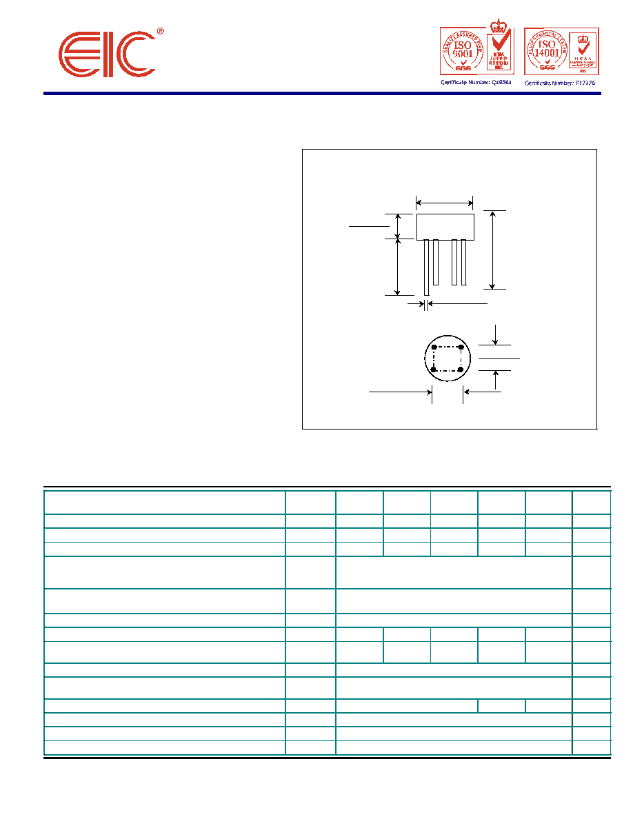
MECHANICAL DATA :
* Case : Reliable low cost construction
utilizing molded plastic technique
* Epoxy : UL94V-O rate flame retardant
* Terminals : Plated leads solderable per
MIL-STD-202, Method 208 guaranteed
* Polarity : Polarity symbols marked on case
* Mounting position : Any
* Weight : 1.29 grams
MAXIMUM RATINGS AND ELECTRICAL CHARACTERISTICS
Rating at 25
∞
C ambient temperature unless otherw ise specified.
Single phase, half w ave, 60 Hz, resistive or inductive load.
For capacitive load, derate current by 20%.
SYMBOL
FB40-C
1000G
FB80-C
1000G
FB125-C
1000G
FB250-C
1000G
FB380-C
1000G
UNIT
Maximum Recurrent Peak Reverse Voltage
V
RRM
100
200
300
600
900
Volts
Maximum RMS Input Voltage R+C -Load
V
RMS
40
80
125
250
380
Volts
Maximum DC Blocking Voltage
V
DC
100
200
300
600
900
Volts
Maximum Average Forw ard Current For
Free Air Operation at Tc = 45
∞
C R+L -Load
I
F(AV)
1.2
Amps.
C -Load
1.0
Peak Forw ard Surge Current Single half sine w ave
on rated load (JEDEC Method) at T
J
= 125
∞
C
I
FSM
30
Amps.
Rating for fusing at T
J
= 125
∞
C ( t < 100 ms.)
I
2
t
10
A
2
S
Maximum Series Resistor C-Load V
RMS
=
±
10%
R
t
1.0
2.0
4.0
8.0
12.0
Maximum load Capacitance + 50%
-10%
C
L
5000
2500
1000
500
200
µ
F
Maximum Forw ard Voltage per Diode at I
F
= 1.0 Amps.
V
F
1.3
Volts
Maximum Reverse Current at Rated Repetitive
Peak Voltage per Diode
I
R
10
µ
A
Maximum Reverse Recovery Time (Note 1)
Trr
150
250
500
ns
Typical Thermal Resistance (Note 2)
R
JA
36
∞
C/W
Operating Junction Temperature Range
T
J
- 50 to + 125
∞
C
Storage Temperature Range
T
STG
- 50 to + 125
∞
C
Notes : 1 ) Measured w ith I
F
= 0.5 Amp., I
R
= 1 Amp., Irr = 0.25 Amp.
2 ) Thermal resistance from Junction to Ambient at 0.375" (9.5 mm) lead length P.C. Board w ith, 0.22" x 0.22" (5.5 x 5.5 mm)
copper Pads.
UPDATE : JUNE 19,1998
RATING
WOB
-
0.39 (10.0)
0.31 (7.87)
0.034 (0.86)
0.028 (0.71)
AC
+
1.10 (27.9)
MIN.
0.22 (5.59)
0.18 (4.57)
0.22 (5.59)
0.18 (4.57)
0.22 (5.59)
0.18 (4.57)
+
-
AC
AC
1.00 (25.4)
MIN.
Dimension in inches and (millimeter)
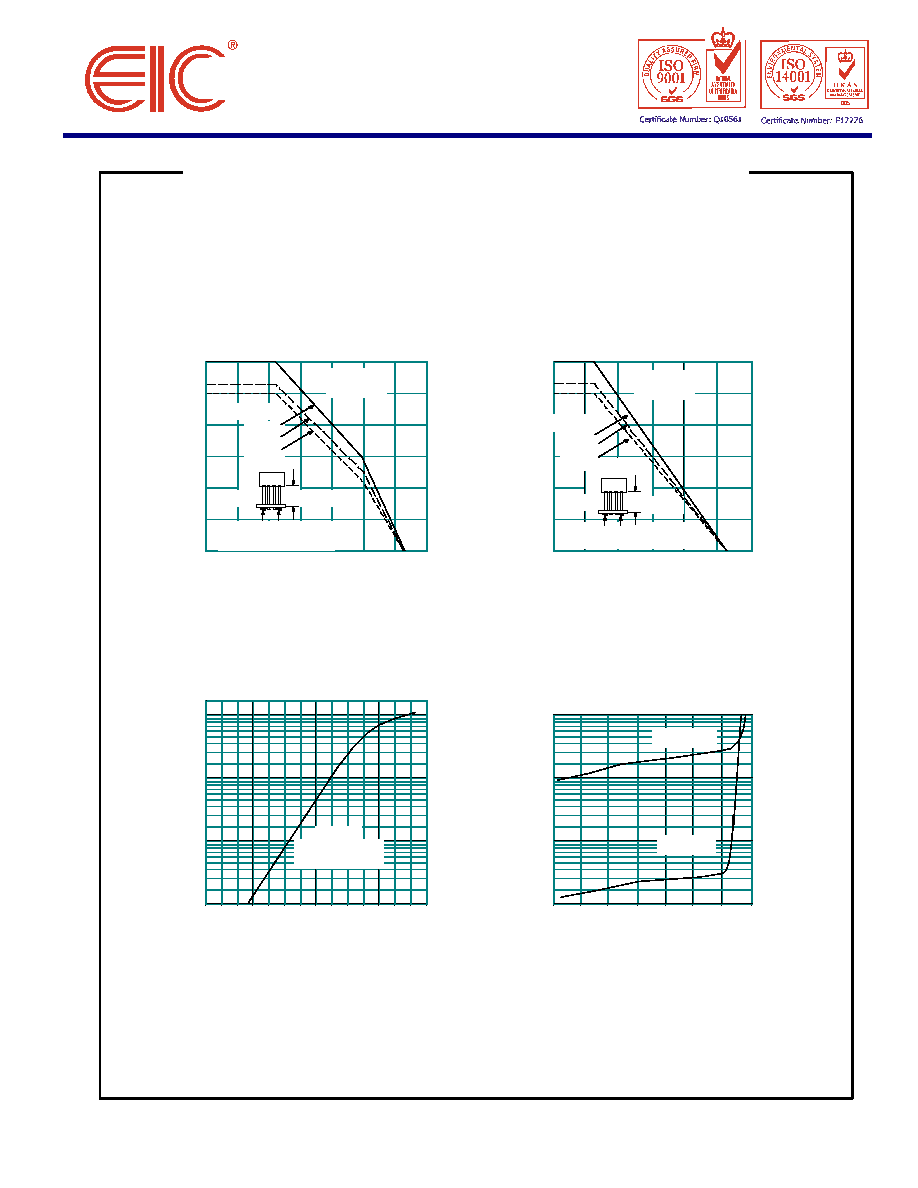
RATING AND CHARACTERISTIC CURVES ( FB40 - FB380/C1000G )
FIG.1 - DERATING CURVE
FIG.2 - DERATING CURVE
FOR OUTPUT RECTIFIED CURRENT
FOR OUTPUT RECTIFIED CURRENT
FB40 C1000G - FB125 C1000G
FB250 C1000G - FB380 C1000G
0
20
40
60
80
100
120
140
20
40
60
80
100
120
140
CASE TEMPERATURE, (
∞
C)
CASE TEMPERATURE, (
∞
C)
FIG.3 - TYPICAL FORWARD CHARACTERISTICS
FIG.4 - TYPICAL REVERSE CHARACTERISTICS
0.4
0.6
0.8
1.0
1.2
1.4
1.6
1.8
FORWARD VOLTAGE, VOLTS
Capacitive Load
Resistive or
Inductive load.
1.0
0.6
0.4
1.2
10
10
1.0
0
0.01
1
80
0.01
0.1
0.1
100
140
0
20
40
60
120
PERCENT OF RATED REVERSE
VOLTAGE, (%)
BRIDGE OUTPUT
FULL WAVE RECTIFIED CURRENT
AVERAGE AMPERES
FORWARD CURRENT, AMPERES
REVERSE CURRENT, MICROAMPERES
T
J
= 25
∞
C
Pulse Width = 300
µ
s
1 % Duty Cycle
T
J
= 100
∞
C
T
J
= 25
∞
C
0.8
0.375(9.5mm)
Copper Pads
0.22" x 0.22" (5.5mm x 5.5mm)
PC Board
20
0.2
Capacitive Load
0-10
µ
F
10-100
µ
F
>100
µ
F
1.0
0.6
0.4
1.2
0
0.8
0.2
BRIDGE OUTPUT
FULL WAVE RECTIFIED CURRENT
AVERAGE AMPERES
Resistive or
Inductive load.
Copper Pads
0.22" x 0.22" (5.5mm x 5.5mm)
0.375(9.5mm)
PC Board
0-10
µ
F
10-100
µ
F
>100
µ
F