©2000 Elantec Semiconductor, Inc.
EL
6259C -
Produ
c
t
B
r
ief
North America: 1-888-352-6832 X 311
Asia: +85-45-682-5820
Europe: +44-18-977-6020
Complete Product Specifications
Elantec Technical Support:
Features
∑
Low output noise = 4.0nA/rt-Hz
∑
High-performance laser diode
driver
∑
Pin compatible with EL6257
∑
Voltage-controlled output current
source to 150 mA per channel,
requiring one external set resistor
per channel
∑
Current-controlled output current
source to 150 mA per channel
∑
Rise time = 1.0 ns
∑
Fall time = 1.1 ns
∑
On chip oscillator with frequency
and amplitude control by use of
external resistors to ground
∑
Oscillator to 500 MHz
∑
Oscillator to 100 mA pk/pk
∑
Single +5V supply (±10%)
∑
Disable feature for power-up
protection and power savings
∑
TTL/CMOS control signals
Applications
∑
DVD-RAM high speed drives
∑
CD-RW applications
∑
Writable optical drives
∑
Laser diode current switching
Ordering Information
Part No
Temp. Range
Package
Outline #
EL6259CU
0∞C to +70∞C
QSOP-24
MDP0040
EL6259C - Product Brief
Low Noise 4-Channel Laser Diode Driver + Oscillator
Jan
uary 31, 2000
General Description
The EL6259C is a low noise four channel laser diode current amplifier
that provides controlled current to a grounded laser diode. The four
amplifiers can provide up to 150 mA per channel of DC or pulsed cur-
rent. Channels 2, 3, and 4 must be used as the write channels, with
switching speeds of approximately one nanosecond rise/fall time. All
four channels are summed together at the I
OUT
output, allowing the
user to create multilevel waveforms in order to optimize laser diode
performance. The level of the output current is set by an analog volt-
age applied to an external resistor which converts the voltage into a
current at the I
IN
pin. The current seen at this pin is then amplified by
100X to become a current source at pin I
OUT
.
An on-chip 500 MHz oscillator is provided to allow current modula-
tion when in the read mode. This is turned on when the EOSC pin is
held high (floating not recommended). Complete control of amplitude
and frequency is set by two external resistors connected to ground at
pins RFREQ and RAMP (see graphs in this data sheet for further
explanation).
Output current pulses are enabled when an `L' signal is applied to the
OE pin. No output current flows when OE is `H', and additional laser
diode protection is provided since the OE input will float high when
open. Complete I
OUT
shut-off is also achieved by holding the CE pin
low, which will override the OE control pins.
The external resistors allow the user to accurately and independently
set each amplifier transconductance by applying a voltage to each
resistor, without restriction on the voltage range, thus ensuring broad
voltage DAC compatibility. Alternatively, the I
IN
pin can be biased
from a current DAC or other current source.
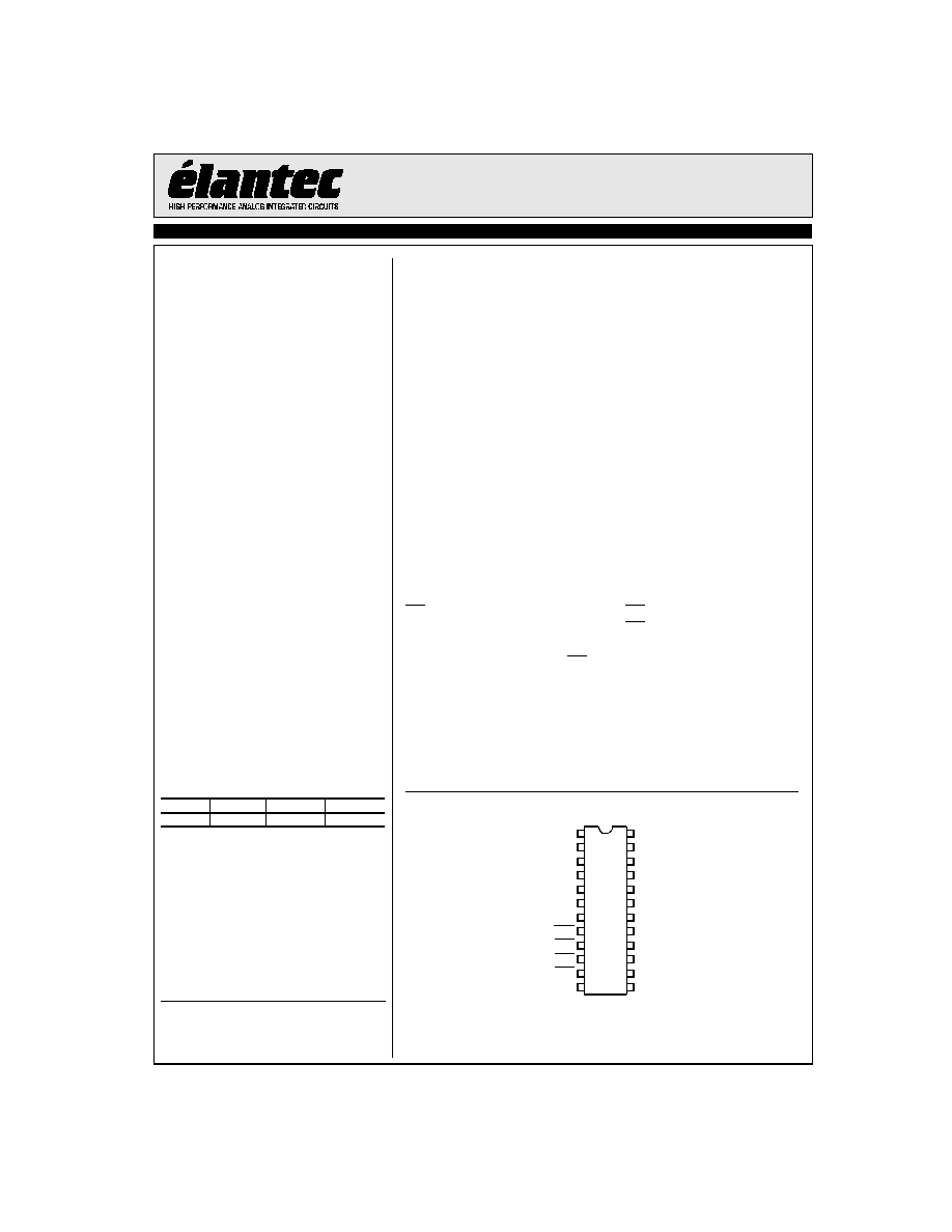
Connection Diagram
1
2
3
4
16
15
14
13
5
6
7
12
11
9
8
10
20
19
18
17
24
23
22
21
GND
I
INR
GND
V
CC
V
CC
I
OUT
RAMP
CE
EOSC
I
IN2
RFREQ
I
IN3
I
IN4
OER
OE2
OE3
OE4
I
OUT
GND
V
CC
V
CC
GND
GND
GND
2
EL6259C - Product Brief
Low Noise 4-Channel Laser Diode Driver + Oscillator
EL625
9C
- Produ
c
t
General Disclaimer
Specifications contained in this product brief are in effect as of the publication date shown. Elantec Semiconductor, Inc. reserves the right to make
changes in the circuitry or specifications contained herein at any time without notice. Elantec Semiconductor, Inc. assumes no responsibility for
the use of any circuits described herein and makes no representations that they are free from patent infringement.
WARNING - Life Support Policy
Elantec Semiconductor, Inc. products are not authorized for and
should not be used within Life Support Systems without the specific
written consent of Elantec Semiconductor, Inc. Life Support sys-
tems are equipment intended to support or sustain life and whose
failure to perform when properly used in accordance with instruc-
tions provided can be reasonably expected to result in significant
personal injury or death. Users contemplating application of Elantec
Semiconductor, Inc. Products in Life Support Systems are requested
to contact Elantec Semiconductor, Inc. factory headquarters to
establish suitable terms & conditions for these applications. Elantec
Semiconductor, Inc.'s warranty is limited to replacement of defec-
tive components and does not cover injury to persons or property or
other consequential damages.
Elantec Semiconductor, Inc.
675 Trade Zone Blvd.
Milpitas, CA 95035
Telephone: (408) 945-1323
(888) 352-6832 (toll free)
Fax:
(408) 945-9305
European Office: 44-18-977-6020
Jan
uary 31, 2000
Printed in U.S.A.
Japan Office:
85-45-682-5820