 | –≠–ª–µ–∫—Ç—Ä–æ–Ω–Ω—ã–π –∫–æ–º–ø–æ–Ω–µ–Ω—Ç: EL7154CS | –°–∫–∞—á–∞—Ç—å:  PDF PDF  ZIP ZIP |
Note: All information contained in this data sheet has been carefully checked and is believed to be accurate as of the date of publication; however, this data sheet cannot be a "controlled document". Current revisions, if any, to these
specifications are maintained at the factory and are available upon your request. We recommend checking the revision level before finalization of your design documentation.
© 2001 Elantec Semiconductor, Inc.
E
L
7
1
0
4
C
,
E
L
7
1
1
4
C
General Description
The EL7104C and EL7114C ICs are matched driver ICs that improve
the operation of the industry-standard TC-4420/29 clock drivers. The
Elantec versions are very high speed drivers capable of delivering
peak currents of 1A into highly capacitive loads. The high speed per-
formance is achieved by means of a proprietary "Turbo-Driver" circuit
that speeds up input stages by tapping the wider voltage swing at the
output. Improved speed and drive capability are enhanced by matched
rise and fall delay times. These matched delays maintain the integrity
of input-to-output pulse-widths to reduce timing errors and clock skew
problems. This improved performance is accompanied by a 10-fold
reduction in supply currents over bipolar drivers, yet without the delay
time problems commonly associated with CMOS drivers.
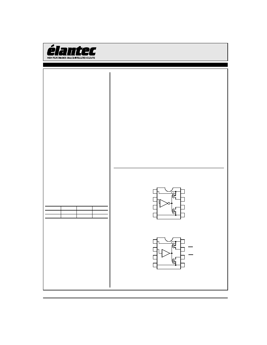
Connection Diagrams
1
2
3
4
8
7
6
5
EL7104C
Non-inverting Driver
1
2
3
4
8
7
6
5
EL7114C
Inverting Driver
V+
IN
NC
GND
V+
P_OUT
N_OUT
GND
V+
IN
NC
GND
V+
P_OUT
N_OUT
GND
Features
∑ Industry-standard driver
replacement
∑ Improved response times
∑ Matched rise and fall times
∑ Reduced clock skew
∑ Low output impedance
∑ Low input capacitance
∑ High noise immunity
∑ Improved clocking rate
∑ Low supply current
∑ Wide operating range
∑ Separate drain connections
Applications
∑ Clock/line drivers
∑ CCD drivers
∑ Ultrasound transducer drivers
∑ Power MOSFET drivers
∑ Switch mode power supplies
∑ Resonant charging
∑ Cascoded drivers
Ordering Information
Part No.
Package
Tape & Reel
Outline #
EL7154CN
8-Pin PDIP
MDP0031
EL7154CS
8-Pin SO
MDP0027
EL7104C, EL7114C
High Speed, Single Channel, Power MOSFET Drivers
A
u
g
u
s
t
2
0
,
2
0
0
1
2
EL7104C, EL7114C
High Speed, Single Channel, Power MOSFET Drivers
E
L
7
1
0
4
C
,
E
L
7
1
1
4
C
Absolute Maximum Ratings
(T
A
= 25∞C)
Supply (V+ to GND)
16.5V
Input Pins
-0.3V to +0.3V above V+
Peak Output Current
4A
Storage Temperature Range
-65∞C to +150∞C
Ambient Operating Temperature
-40∞C to +85∞C
Operating Junction Temperature
+125∞C
Power Dissipation:
SO
570mW
PDIP
1050mW
Important Note:
All parameters having Min/Max specifications are guaranteed. Typ values are for information purposes only. Unless otherwise noted, all tests are at the
specified temperature and are pulsed tests, therefore: T
J
= T
C
= T
A
.
DC Electrical Characteristics
T
A
= 25∞C, V+ = 15V unless otherwise specified.
Parameter
Description
Test Conditions
Min
Typ
Max
Unit
Input
V
IH
Logic "1" Input Voltage
2.4
V
I
IH
Logic "1" Input Current
@V+
0.1
10
µA
V
IL
Logic "0" Input Voltage
0.8
V
I
IL
Logic "0" Input Current
@0V
0.1
10
µA
V
HVS
Input Hysteresis
0.3
V
Output
R
OH
Pull-Up Resistance
I
OUT
= -100 mA
1.5
4
R
OL
Pull-Down Resistance
I
OUT
= +100 mA
2
4
I
OUT
Output Leakage Current
V+/GND
0.2
10
µA
I
PK
Peak Output Current
Source
Sink
4.0
4.0
A
I
DC
Continuous Output Current
Source/Sink
200
mA
Power Supply
I
S
Power Supply Current
Input = V+ EL7104C
EL7114C
4.5
1
7.5
2.5
mA
V
S
Operating Voltage
4.5
16
V
AC Electrical Characteristics
T
A
= 25∞C, V = 15V unless otherwise specified.
Parameter
Description
Test Conditions
Min
Typ
Max
Unit
Switching Characteristics (V
DD
= V
H
= 12V; V
L
= -3V)
t
R
Rise Time
C
L
= 1000 pF
7.5
ns
C
L
= 2000 pF
10
20
ns
t
F
Fall Time
C
L
= 1000 pF
10
ns
C
L
= 2000 pF
15
20
ns
t
D-ON
Turn-On Delay Time
See Timing Table
18
25
ns
t
D-OFF
Turn-Off Delay Time
See Timing Table
18
25
ns
3
EL7104C, EL7114C
High Speed, Single Channel, Power MOSFET Drivers
E
L
7
1
0
4
C
,
E
L
7
1
1
4
C
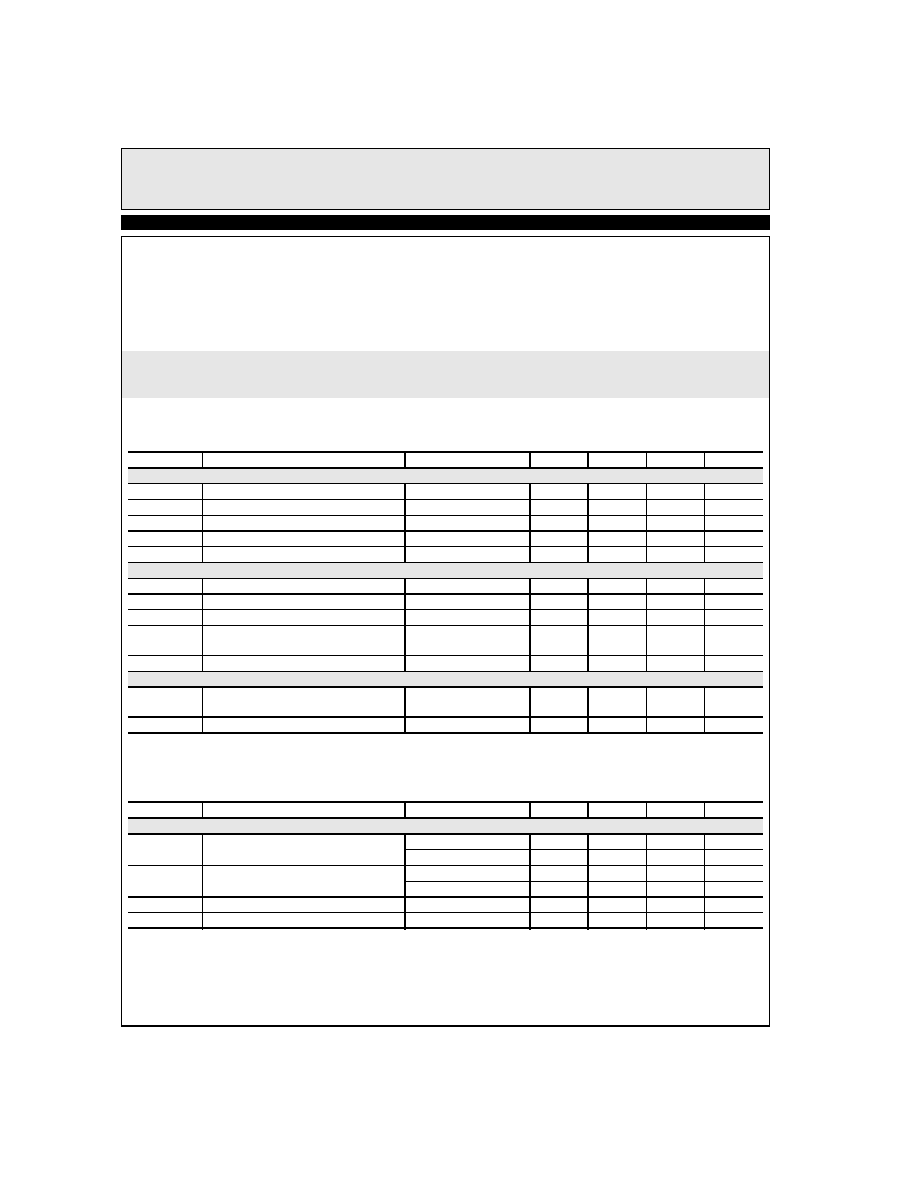
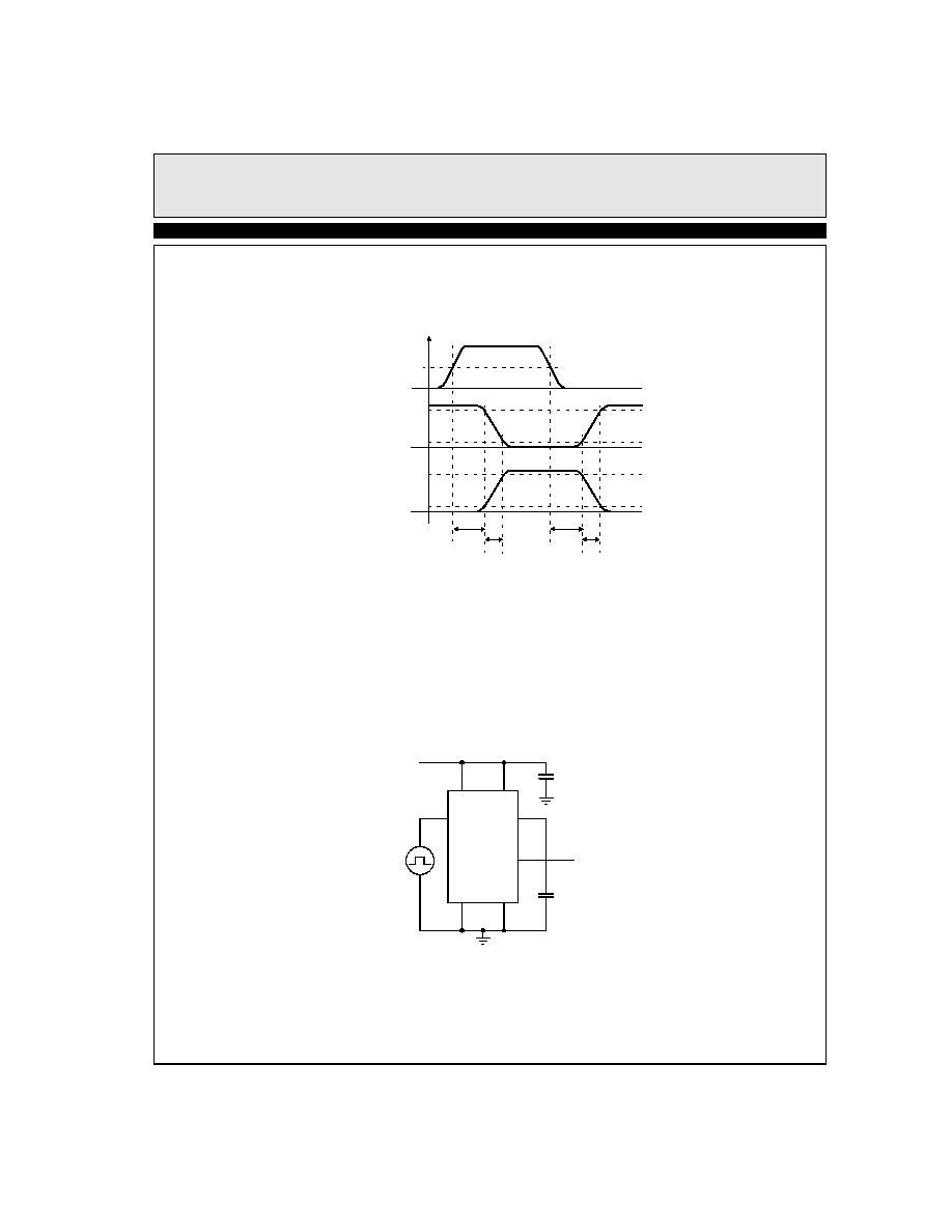
Timing Table
Standard Test Configuration
5V
2.5V
90%
10%
90%
10%
0
t
D1
t
D2
t
F
t
R
t
R
t
F
Inverted
Output
EL7114C
Non-
inverted
Output
Input
1
8
2
4
5
6
7
D.U.T.
Input
Signal
Output
Signal
4.7µF
2000pF
4
EL7104C, EL7114C
High Speed, Single Channel, Power MOSFET Drivers
E
L
7
1
0
4
C
,
E
L
7
1
1
4
C
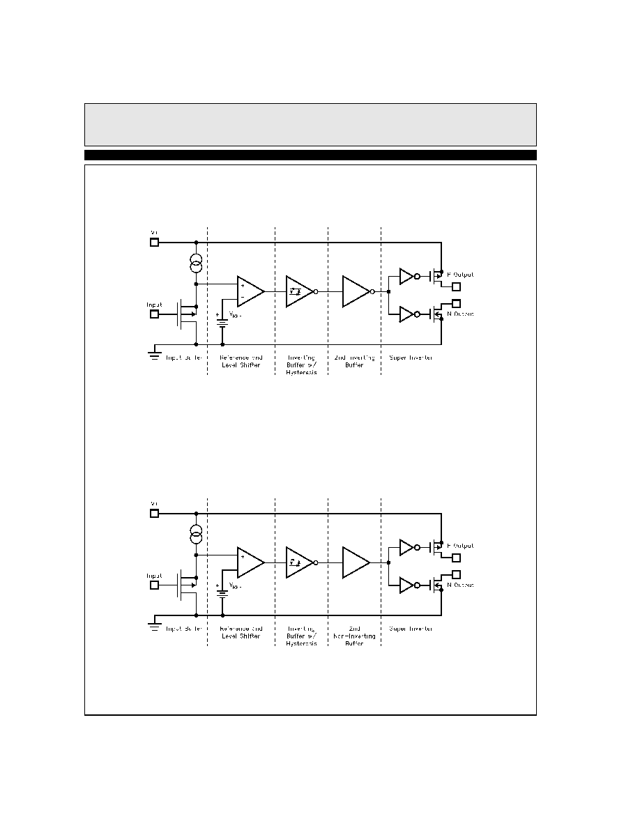
EL7104C Simplified Schematic
EL7114C Simplified Schematic
5
EL7104C, EL7114C
High Speed, Single Channel, Power MOSFET Drivers
E
L
7
1
0
4
C
,
E
L
7
1
1
4
C
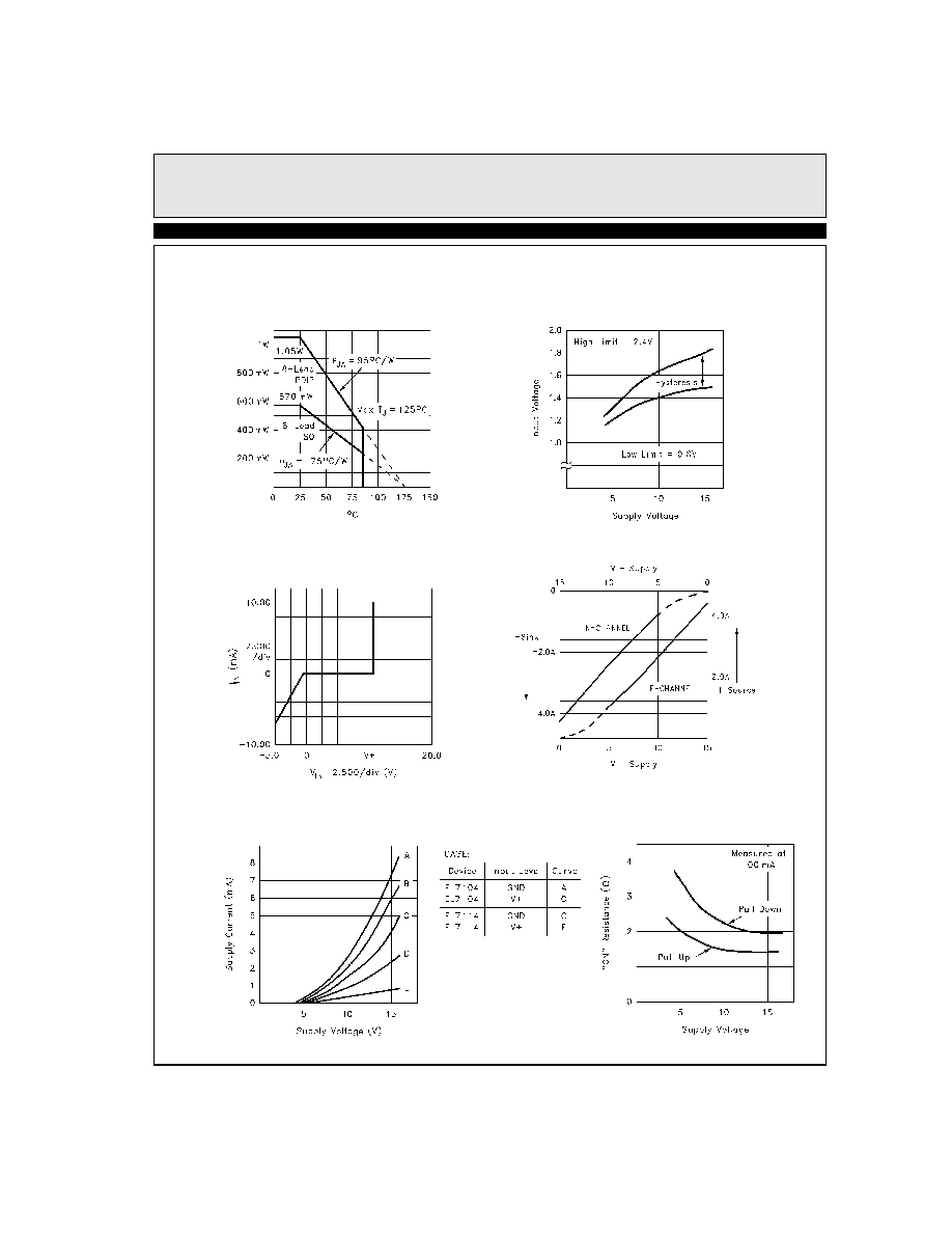
Typical Performance Curves
Max Power/Derating Curves
Switch Threshold vs
Supply Voltage
Peak Drive vs Supply Voltage
Input Current vs Voltage
Quiescent Supply Current
"ON" Resistance vs Supply Voltage
6
EL7104C, EL7114C
High Speed, Single Channel, Power MOSFET Drivers
E
L
7
1
0
4
C
,
E
L
7
1
1
4
C
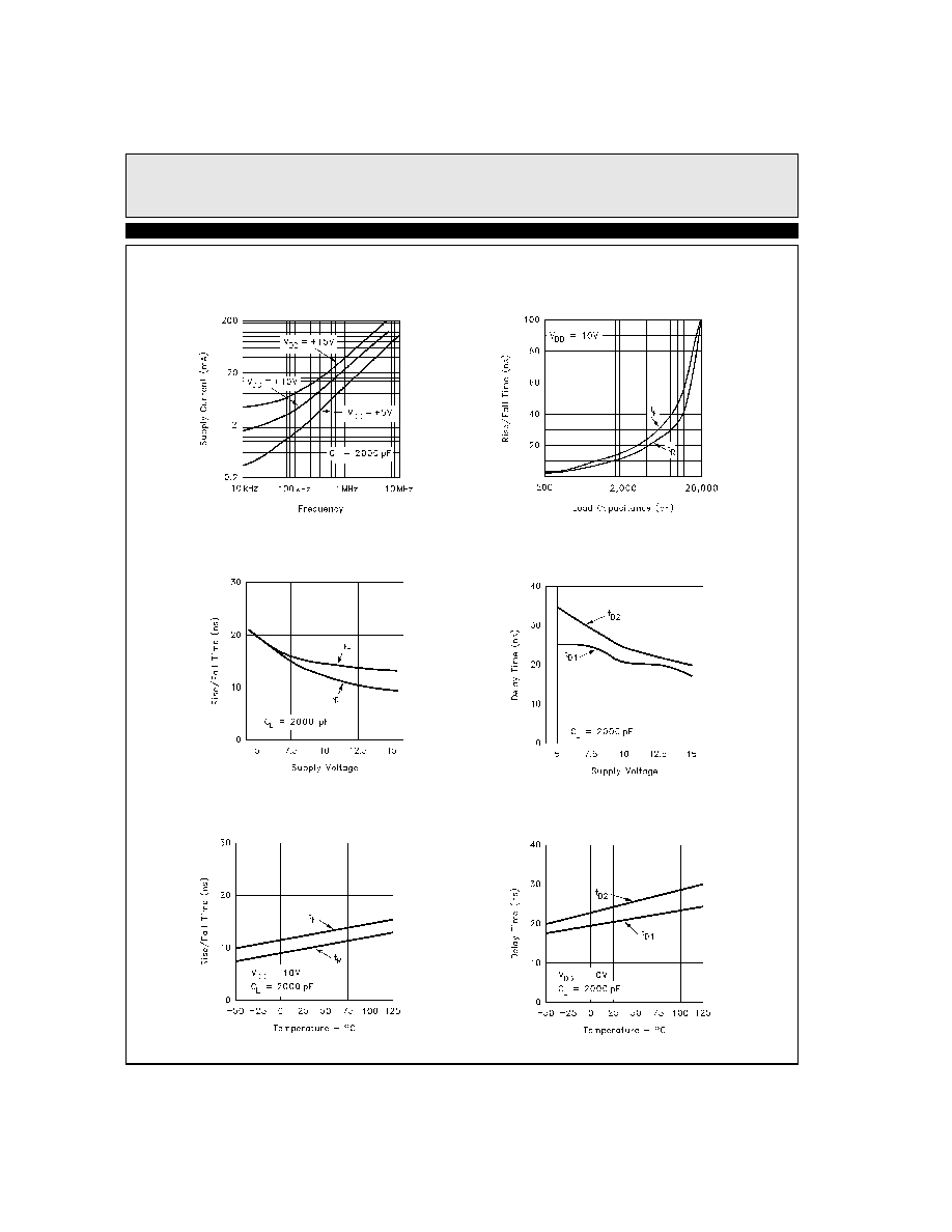
Average Supply Current vs
Voltage and Frequency
Rise/Fall Time vs Load
Rise/Fall Time vs Supply Voltage
Propagation Delay vs Supply Voltage
Rise/Fall Time vs Temperature
Rise/Fall Time vs Temperature

7
EL7104C, EL7114C
High Speed, Single Channel, Power MOSFET Drivers
E
L
7
1
0
4
C
,
E
L
7
1
1
4
C
General Disclaimer
Specifications contained in this data sheet are in effect as of the publication date shown. Elantec, Inc. reserves the right to make changes in the cir-
cuitry or specifications contained herein at any time without notice. Elantec, Inc. assumes no responsibility for the use of any circuits described
herein and makes no representations that they are free from patent infringement.
WARNING - Life Support Policy
Elantec, Inc. products are not authorized for and should not be used
within Life Support Systems without the specific written consent of
Elantec, Inc. Life Support systems are equipment intended to sup-
port or sustain life and whose failure to perform when properly used
in accordance with instructions provided can be reasonably
expected to result in significant personal injury or death. Users con-
templating application of Elantec, Inc. Products in Life Support
Systems are requested to contact Elantec, Inc. factory headquarters
to establish suitable terms & conditions for these applications. Elan-
tec, Inc.'s warranty is limited to replacement of defective
components and does not cover injury to persons or property or
other consequential damages.
A
u
g
u
s
t
2
0
,
2
0
0
1
Printed in U.S.A.
Elantec Semiconductor, Inc.
675 Trade Zone Blvd.
Milpitas, CA 95035
Telephone: (408) 945-1323
(888) ELANTEC
Fax:
(408) 945-9305
European Office: +44-118-977-6020
Japan Technical Center: +81-45-682-5820