 | –≠–ª–µ–∫—Ç—Ä–æ–Ω–Ω—ã–π –∫–æ–º–ø–æ–Ω–µ–Ω—Ç: K75-74 | –°–∫–∞—á–∞—Ç—å:  PDF PDF  ZIP ZIP |

145
K75-74
____________________________________________________________________________________
PAPER ≠ FILM CAPACITORS WITH ELECTRODES
.
75-54.
:
.
Designed to operate in AC current circuit
and in pulse mode.
Can be used instead of 75-54.
Design:
cylindrical housing made of
polymeric materials. Axial terminals.
" "
Design " "
" "
Design "b"
2
. (2 holes)
M6*
*
L
3*
20*
D
L
12
max
12
max
12±
1
L
25
max
25
max
M6-
6g
D
D
" "
Design " "
0,01...4,7
Rated capacitance
0.01...4.7 F
5,0...40
Rated voltage
5.0...40 kV
+10; +20%
Capacitance tolerance
+10; +20%
f = 1
< 0,006
Dissipation factor at f = 1 kHz
< 0.006
r < 0,22
> 3000
Insulation
resistance
at r < 0.22 F
> 3000 MOhm
r > 0,22
1000
.
Time
constant
at r > 0.22 F
1000 MOhm.F
-60...+55
o
C
Operating
temperature
range
-60...+55
o
C
5000
Operating time
5000 hours
:
75-74 ≠ 5
≠ 2,2
± 20%
Ordering example:
Capacitor K75-74b ≠ 5 kV ≠ 2.2 F ± 20%

146
D, mm
L, mm
Ur, kV
Cr, F
Rated
value
Limit
discrepancy
Rated
value
Limit
discrepancy
Mass, g
max
Design
0.10
24
±1.65
60
0.22
34
120
0.47
45
±1.95
90
±2.7
220
a (a)
1.0
53
430
2.2
75
±2.3
930
5.0
4.7
105
±2.7
140
±3.15
1900
(b), ( )
0.047
34
120
0.10
45
±1.95
220
0.22
67
90
±2.7
460
a (a)
0.47
67
±2.3
760
10
1.0
105
±2.7
1750
0.022
36
200
0.047
50
±1.95
410
0.10
71
140
±3.15
830
0.22
67
±2.3
1600
20
0.47
100
±2.7
3300
0.01
36
410
0.022
48
±1.95
760
0.047
67
±2.3
1600
40
0.10
100
±2.7
270
±4.05
3200
(b)
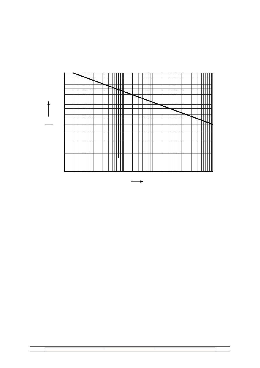
Um
f
Permissible amplitude of AC sinusoidal component of ripple voltage Um as a function of frequency f
Um / Ur, %
f, Hz
100
10
1
100
1000
1
2
3
4
5
6
50
1
10
10000
1)
5,0
(0,1
)
2)
5
(0,22
); 10
(0,047
); 20
(0,022
);
3)
5
(0,47
); 10
(0,1
);
20
(0,047
); 40
(0,022
);
4)
5
(1,0
); 10
(0,22
);
20
(0,1
); 40
(0,047
);
5)
5
(2,2
); 10
(0,47
);
20
(0,22
); 40
(0,1
);
6)
5
(4,7
); 10
(1,0
); 20
(0,47
)
1)
5.0 kV (0.1 F)
2)
5 kV (0.22 F); 10 kV (0.047 F); 20 kV (0.022 F);
3)
5 kV (0.47 F); 10 kV (0.1 F);
20 kV (0.047 F); 40 kV (0.022 F);
4)
5 kV (1.0 F); 10 kV (0.22 F);
20 kV (0.1 F); 40 kV (0.047 F);
5)
5 kV (2.2 F); 10 kV (0.47 F);
20 kV (0.22 F); 40 kV (0.1 F);
6)
5 kV (4.7 F); 10 kV (1.0 F); 20 kV (0.47 F)
147
U
p
,
.
Peak-to-peak pulse voltage U
p
must not exceed the values defined from the Figure below.
U
p
F
p
Permissible amplitude of peak-to-peak pulse voltage U
p
as a function of pulse repetition rate F
p
100
80
70
60
50
40
30
25
20
15
10
%
10
-1
1
10
10
2
10
3
10
4
Hz
F
p
U
p
U
r
U
p
I
p
F
p
,
:
U
p
I
p
F
p
P,
P ≠
,
;
-
,
,
;
-
,
,
:
- 0,8 ≠
;
- 1,0 -
(
)
20%;
-
,
, -
;
I
p
≠
,
;
F
p
-
.
Permissible combinations of U
p
I
p
F
p
must not exceed the values calculated from the following
formula:
U
p
I
p
F
p
P,
where
P - a parameter specifying loss power tolerance at a natural convective heat transfer along the
lateral surface that is given in the table.
- a coefficient that allows for the capacitor discharge time. It depends on the duration of the
discharge current pulse and is determined from the Figure below
- a coefficient that allows for the discharge mode of the capacitor and is equal to:
- 0.8 ≠ for the aperiodic and oscillatory modes with one half-wave of the current;
- 1.0 - for the pulse mode with the discharge depths (voltage derating ratio) up to 20%;
- values measured from the figure for oscillatory damping mode of discharge
I
p
≠ discharge current amplitude of the capacitor
F
p
- pulse repetition rate

148
Cr, F
Ur, kV
P 10
-6
, VA/c
Cr, F
Ur, kV
P 10
-6
, VA/c
0.10
0.22
0.47
1.0
2.2
4.7
5
472
642
830
1293
1406
2193
0.022
0.047
0.10
0.22
0.47
20
971
1274
1642
2873
3615
0.047
0.10
0.22
0.47
1
10
642
830
1113
1592
2123
0.010
0.022
0.047
0.1
40
1871
2291
2873
3573
p
(
0,5 I
p
)
as a function of the discharge current pulse duration
p
(at a level of 0.5 I
p
)
20
10
1
0.1
0.1
1
10
100
p
s

149
U
rev
/U
p
as a function of U
rev
/U
p
for the oscillatory damped mode of discharge
4
1
2
3
0
0.2
0.3
0.4
0.5
0.6
0.7
0.8
0.9
U
rev
U
p
U
rev
≠
;
here U
rev
≠ amplitude of a reverse pulse voltage