 | –≠–ª–µ–∫—Ç—Ä–æ–Ω–Ω—ã–π –∫–æ–º–ø–æ–Ω–µ–Ω—Ç: –ö75-93 | –°–∫–∞—á–∞—Ç—å:  PDF PDF  ZIP ZIP |

182
75-93
__________________________________________________________________________________________
METALLIZED FILM IMPREGNATED CAPACITORS
.
75-15.
:
,
.
Designed to operate in DC and ripple current
and in pulse mode.
Can be used instead of K75-15.
Design: metallic sealed housing.
L
H
B
A
M12
h
0,68... 1500
Rated capacitance
0.68... 1500 F
3 ... 40
Rated voltage
3 ... 40 kV
±10%; ±20%
Capacitance tolerance
±10%; ±20%
f=50
<0.004
Dissipation factor at f=50Hz
<0.004
> 500
.
Time constant
> 500 MOhm.F
-60...+55
o
C
Operating
temperature
range
-60...+55
o
C
a 50000
Operating time
50000 hours
10
Shelf life
10 years
2 (
15150-
69)
Climatic categories
RH 98%. 35
o
C. 21 days
:
75-93-5
-75
- ±10%
Ordering example:
Capacitor K75-93-5kV-75F - ±10%

183
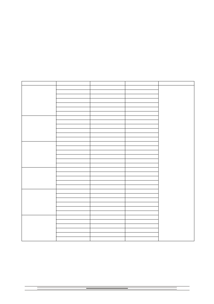
Dimensions, mm
Ur, kV
Cr, F
L
Limit
discrepancy
B
Limit
discrepancy
H
Limit
discrepancy
A,
mm
h,
max
Mass,
g
max
30 100
±2.7
2.2
75
90 ±2.7
190 ±3.6
4.1
180 290
±4.05
10
330
170 ±3.15
140
490 ±4.85
85
16.5
510 280 ±4.05
390 ±4.45 140
26
1000 490
±4.85
49
3
1500
420 ±4.85
170
±3.15
690 ±6.25
210
69
15 100
±2.7
2.5
30
90 ±2.7
190 ±3.6
4.1
75
170 ±3.15
140
85
10
150 280 ±4.05
290 ±4.05
140 20
330 420 ±4.85
390 ±4.45 210
40
5
510 550
±5.5
170
±3.15
490 ±4.85 280
64.5
6.8 190
±3.6
4.1
12
90 ±2.7
6.5
18
170 ±3.15
140
85
10
36
290 ±4.05
20
75
280 ±4.05
140
33
10
150 550
±5.5
170
±3.15
490 ±4.85
280
65
64.5
4.7 210
±3.6
4.5
6.8
170 ±3.15 90 ±2.7
85
8.5
22
390 ±4.45
26
33
280 ±4.05
140
38
16
68 550 ±5.5
170 ±3.15
560 ±5.5
280 74
2.2 90
±2.7
290
±4.05
6.5
4.7 390
±4.45
13
6.8
170 ±3.15
140
85
19
15 280 ±4.05
140
38
22
560 ±5.5
56
24
33
420 ±4.85
170
±3.15
690 ±6.25
210
80
69
0.68 90
±2.7
6.5
1
290 ±4.05
10
2.2
170 ±3.15
140
85
17
4.7
280 ±4.05
140
33
6.8
490 ±4.85
49
40
10
420 ±4.85
170
±3.15
690 ±6.25
210
140
69
:
Permissible parameters of pulse mode must not exceed the values calculated from the following
formulas:
T
A
r
r
R
R
F
C
U
F
F
C
U
/
20
/
2
.
1
8
.
1
lg
10
4
.
2
2
2
2
4
,
,
1
.
1
0
I
F
C
U
r
U -
,
;
F -
,
;
≠
, .
I
0
= 150 ;
where
U - amplitude of peak-to-peak pulse voltage, V;
F - pulse repetition rate;
≠ discharge current pulse duration, s;
I
0
= 150 .
184
U
2
m
CF tg
g
+2( U
m
FC)
2
R
A
< 20 / R
T
,
R
T
, tg
g
, R
A
-
,
:
Permissible amplitude of AC sinusoidal component of voltage at amb is expressed by
U
2
m
CF tg
g
+2( U
m
FC)
2
R
A
< 20 / R
T
,
where
R
T
, tg
g
, R
A
-
are parameters given in the table:
Ur, V
Cr, F
RA*10
3
, Ohm
RT,
o
C/W
tg g*10
4
30 2.1
3.42
75 1.2
1.93
180 1.4 1.62
330 1.2 0.98
510 1.1 0.87
1000 1.1 0.48
3
1500 1.2 0.35
15 3.0
3.42
30 1.6
1.93
75 1.8
1.62
150 1.4 1.15
330 1.2 0.60
5
510 2.1 0.37
6.8 5.7 1.93
12 3.4
1.31
18 5.6
1.62
36 3.5
1.15
75 2.9
0.70
10
150 3.7 0.37
4.7 13.4 1.77
6.8 7.2 0.99
22 6.8
0.87
33 5.3
0.66
16
68 4.8
0.35
2.2 19.8 1.31
4.7 24.9 1.23
6.8 17.3 0.98
15 10.1
0.70
22 9.3
0.48
24
33 8.9
0.35
0.68 64.5 1.31
1 109.1
1.62
2.2 55.1 0.98
4.7 28.6 0.70
6.8 17.9 0.48
40
10 14.6
0.35
3

185
K
Minimum operating time as a function of coefficient K
4.7 (5.0)
1
1.2
0.9
4 (4.3)
3 (3.3)
5 (5.3)
K
lg (lg N)
3.5 (3.8)
4.5 (4.8)
1.1
:
-
;
-
.
K=U/Ur
Minimum operating time given:
- in brackets in pulses ;
- without brackets in hours.
Where K=U/Ur