109
K78-41
________________________________________________________________________________
METALLIZED POLYPROPYLENE FILM CAPACITORS
.
:
.
Designed to operate in DC and ripple
current in pulse mode.
Design:
cylindrical housing made of
polymeric materials.
"a"
Design "a"
"b"
Design "b"
"c"
Design "c"
"d"
Design "d"
" "
Design " "
25
ma
x
0.5±0.1
D
View A
4 0.15
2 0.3
2
. (2 holes)
L
25
ma
x
A
25
ma
x
D
L
25
ma
x
0.8 0.1
20
ma
x
D
L
M6-6g
20
ma
x
1,
5
L
20
+5
20
20
+5
4
9
6,5
D
3*
D
L
2
. (2 holes)
M6*
*
20*
4.0...800
Rated capacitance
4.0...800 F
(
-60
o
C...+50
o
C)
630...3000
Rated voltage
(temperature range
-60
o
C...+50
o
C)
630...3000 V
+10%
Capacitance tolerance
+10%
<0,005
Dissipation
factor
<0.005
> 500
.
Time constant
> 500 MOhm.F
-60...+70
o
C
Operating
temperature
range
-60...+70
o
C
150...3000 A
Discharge current amplitude
150...3000 A
10
5
.
Operating time
10
5
imp.
10
Shelf life
10 years
:
78-41 - 1000 - 100
± 10%
Ordering example:
Capacitor K78-41 - 1000V - 100F ± 10%
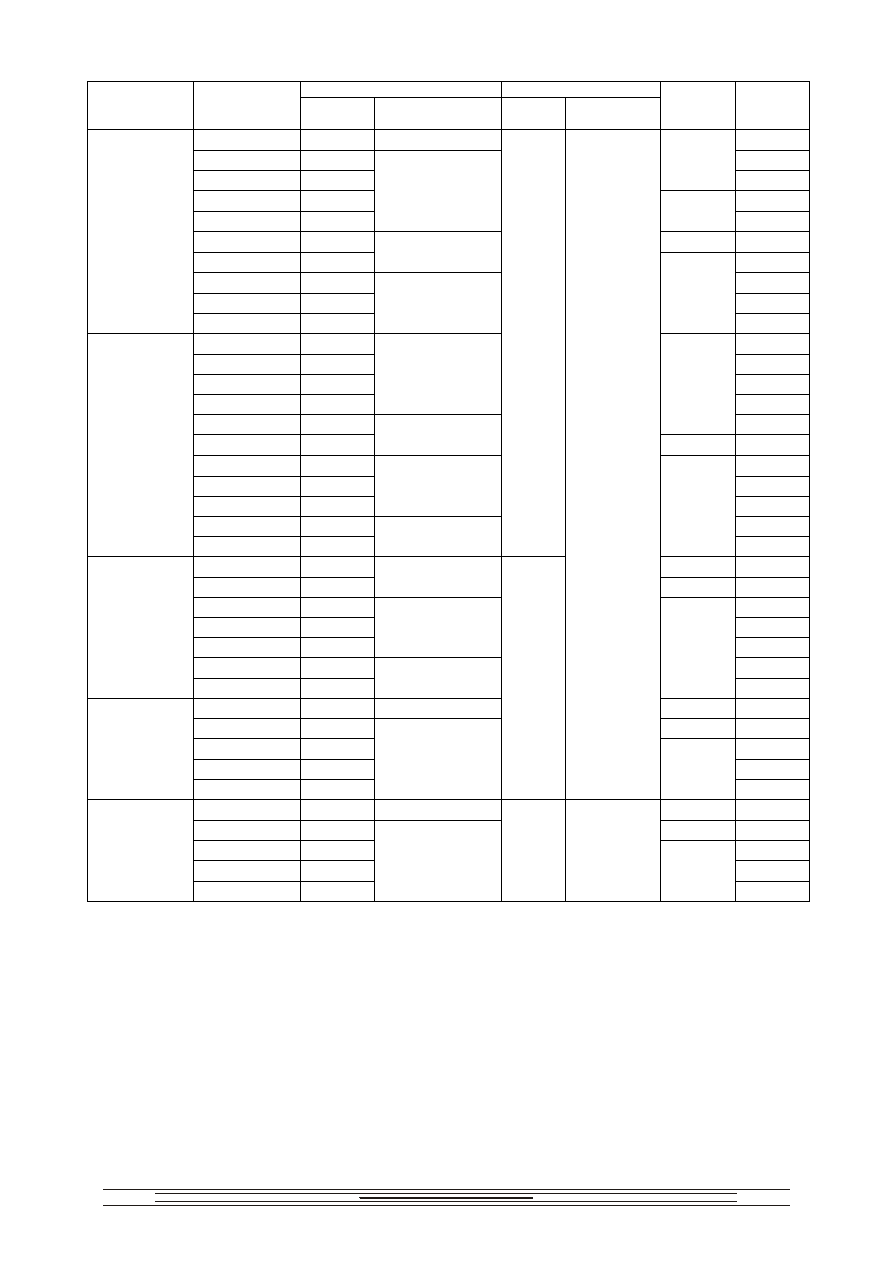
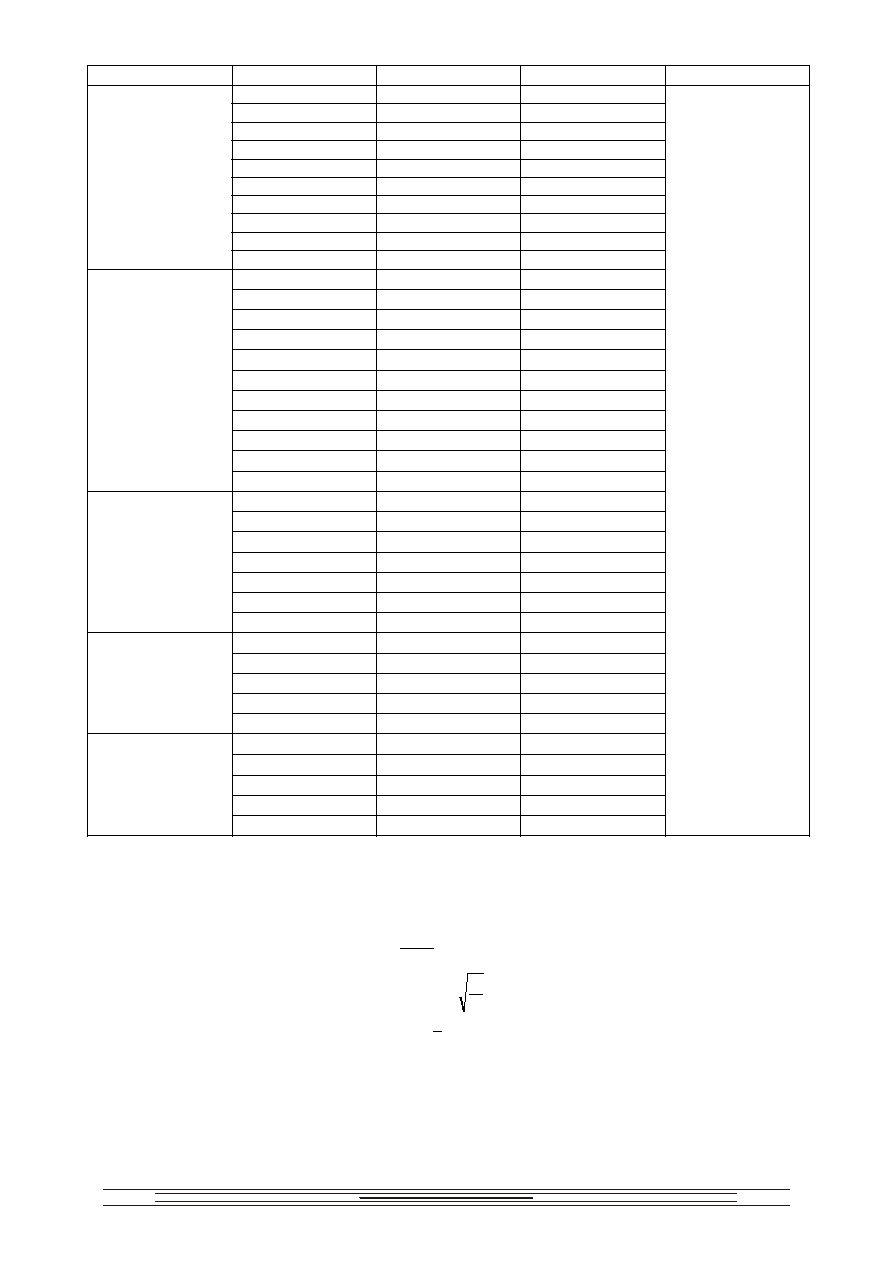
110
D, mm
L, mm
Ur, V
Cr,
F
Rated
value
Limit
discrepancy
Rated
value
Limit
discrepancy
Design
Mass, g,
max
10
17
1.35
30
20
22 45
40
30
a, b
85
60
35 120
80
40
1.65
b, c
150
100
45
b, c, d,
190
200
60
2.3
340
400
85 680
600
105 1100
630
800
120
, d,
1400
4 16
25
6 19
35
8 21
40
10 23
1.65
50
20 30
a, b
85
40 42
1.95
b,
170
60 50
240
80 60
340
100 65
2.3
400
200 92
800
1000
400 127
2.7
85
, d,
1500
20
30
a, b
170
40
40
1.95
b, c
300
60
50 470
80
55 570
100
62
2.3
720
200
85 1400
1250
300
105
2.7
b, c, d,
2100
10 30 1.95
,
170
20 42
b,
c,
340
40 60
680
80 80
1200
2000
100 92
2.3
170
2.7
, d,
1600
10 37 1.95
, ,
400
20 50
b,
c,
720
40 70
1400
60 87
2200
3000
80 100
2.3
260
3.15
, d,
2900
U
2
m
CF tg
g
+2( U
m
FC)
2
R
A
< 20 / R
T
,
R
T
, tg
g
, R
A
-
,
:
Permissible amplitude of AC sinusoidal component of voltage at amb is expressed by
U
2
m
CF tg
g
+2( U
m
FC)
2
R
A
< 20 / R
T
,
where R
T
, tg
g
, R
A
- are parameters given in the table:
112
Im -
Im
max
-
(
).
where
U - amplitude of peak-to-peak pulse voltage, V;
F - pulse repetition rate;
≠ discharge current pulse duration, s;
I
0
= 8 ≠ for design "a";
I
0
= 25 ≠ for design "b";
I
0
= 40 ≠ for design "c";
I
0
= 80 ≠ for design "d", " "
Im - discharge current amplitude
Im
max
- Max. discharge current amplitude that is given in the table below
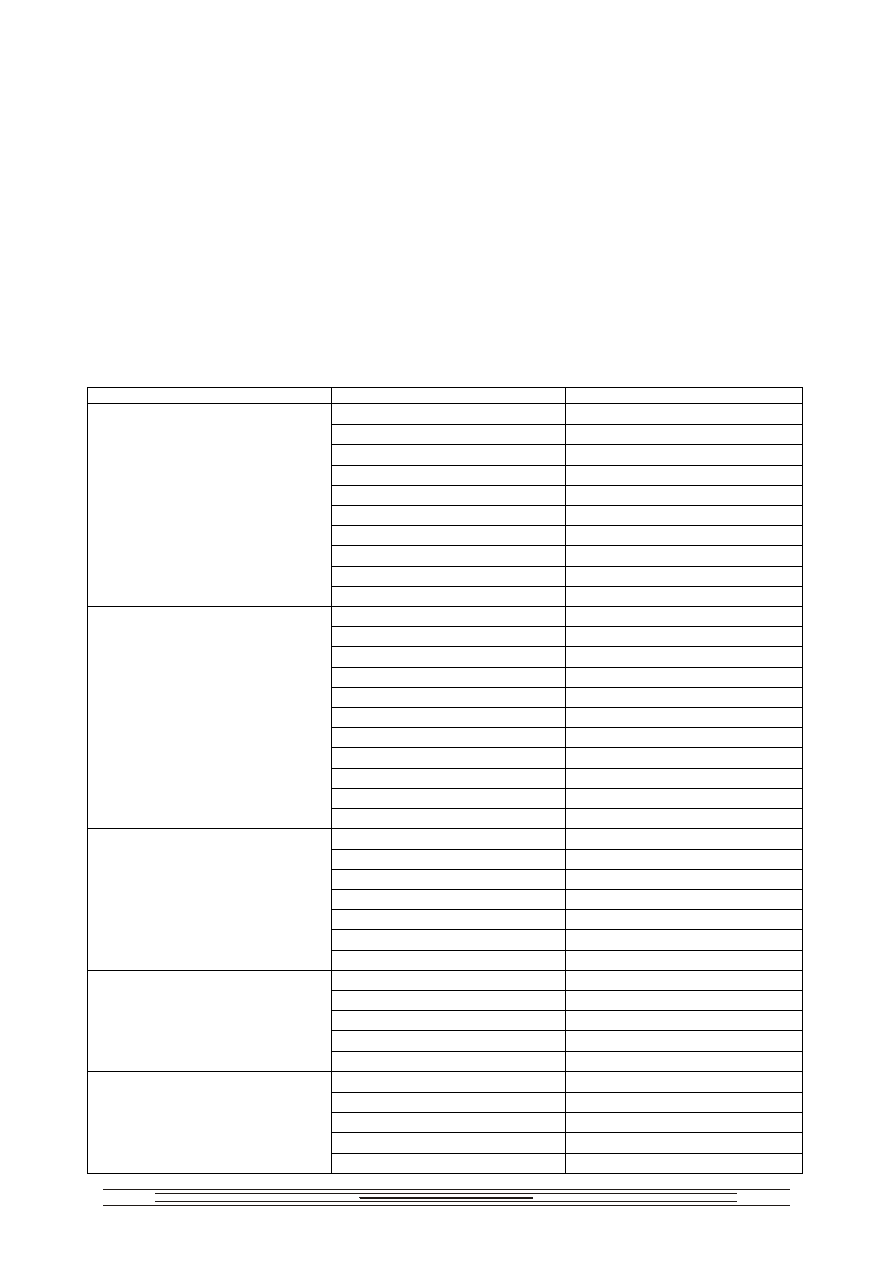
,
Max. discharge current amplitude, A
Ur, V
Cr, F
I
m
, A
10
400
20
500
40
600
60
1000
80
1000
100
2000
200
2000
400
3000
600
3000
630
800
3000
4
150
6
200
8
300
10
400
20
500
40
600
60
1000
80
1000
100
2000
200
2500
1000
400
3000
20
600
40
1000
60
1000
80
1000
100
2000
200
2000
1250
300
2500
10
300
20
500
40
1000
80
2000
2000
100
2000
10
500
20
1000
40
1000
60
2000
3000
80 2000
113
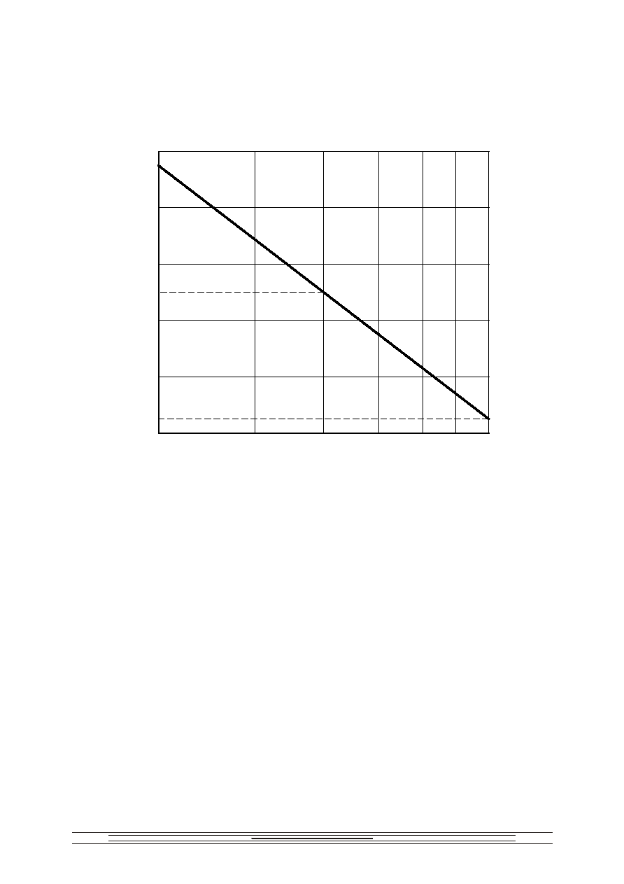
K
Minimum operating time as a function of coefficient K
lg t (lg N)
K
1
1.5
2
3.7 (4)
5.7 (6)
1.7 (2)
0.2 (0.5)
1.75
1.25
0.75
7.7 (8)
9.2 (9.5)
0.5
4.7 (5)
:
-
;
-
.
K=U/Ur
Minimum operating time given:
- in brackets in pulses ;
- without brackets in hours.
Where K=U/Ur