 | –≠–ª–µ–∫—Ç—Ä–æ–Ω–Ω—ã–π –∫–æ–º–ø–æ–Ω–µ–Ω—Ç: ELM310P | –°–∫–∞—á–∞—Ç—å:  PDF PDF  ZIP ZIP |

ELM310
Elm Electronics ≠ Circuits for the Hobbyist
< http://www.elmelectronics.com/ >
Connection Diagram
PDIP and SOIC
(top view)
V
DD
V
SS
1
2
3
4
8
7
6
5
Stepper Motor Controller
The ELM310 is an interface circuit for use
between high speed logic outputs and four phase
stepper motor driver circuits. By suitably debouncing
mechanical switches, the circuit could also be used
for manually controlling stepper motors as well.
This circuit supports two popular modes of
operation, and can be switched between the two `on
the fly'.
The full-step, or single phase wave mode, as it
is sometimes called, is entered into at powerup. This
mode provides sequential single phase output
signals for driving a variety of circuits with only one
output active at any one time.
The other mode that the ELM310 supports is the
half-step. In this case, there are eight distinct output
patterns as opposed to the four for the full-step
mode. For each step, the pattern alternates between
a single winding being energized, and two adjacent
windings, providing eight steps in total.
C
A
Dir
Description
∑ Stepper motor drive logic
∑ Process sequencing
∑ Sequential left/right LED driver
Applications
Block Diagram
1 of 5
∑ Low power CMOS design - typically 1mA at 5V
∑ Wide supply range - 3.0 to 5.5 volt operation
∑ Two inputs control both mode and motion
∑ No external timing components
∑ Completely static operation - will maintain a step
position indefinitely
∑ High current drive outputs - up to 25 mA
∑ Both half and full stepping supported
∑ Very high speed - up to 25000 steps per second
Features
ELM310DSB
B
D
Step
5
D
4
Step
C
Dir
7
B
6
Mode
Switch
Logic
3
2
A
Full
Half
CW
Step

ELM310
Elm Electronics ≠ Circuits for the Hobbyist
< http://www.elmelectronics.com/ >
Pin Descriptions
Ordering Information
These integrated circuits are available in either the 300 mil plastic DIP format, or in the 200 mil SOIC surface
mount type of package. To order, add the appropriate suffix to the part number:
300 mil Plastic DIP............................... ELM310P
200 mil SOIC..................................... ELM310SM
2 of 5
All rights reserved. Copyright ©1999 Elm Electronics.
Every effort is made to verify the accuracy of information provided in this document, but no representation or warranty can be
given and no liability assumed by Elm Electronics with respect to the accuracy and/or use of any products or information
described in this document. Elm Electronics will not be responsible for any patent infringements arising from the use of these
products or information, and does not authorize or warrant the use of any Elm Electronics product in life support devices and/or
systems. Elm Electronics reserves the right to make changes to the device(s) described in this document in order to improve
reliability, function, or design.
V
DD
(pin 1)
This pin is the positive supply pin, and should
always be the most positive point in the circuit.
Internal circuitry connected to this pin is used to
provide power on reset of the microprocessor, so
an external reset signal is not required. Refer to
the Electrical Characteristics section for further
information.
A (pin 2)
This is the active high output drive signal for the
(first) phase A winding. Normally, this output
would be the first to be energized when starting a
stepping sequence, and is always the first state
entered into internally on powerup. After powerup,
however, the ELM310 treats this pin specially,
maintaining it at a low level until the first step
command is received. This in effect keeps the
motor off until selected by control circuitry.
Dir (pin 3)
This pin determines the sequence that the outputs
will be energized in. A high input on the Dir pin
while the step input is pulsed will cause a single
clockwise step, while a low level will cause a
counter-clockwise step. (Refer to Figures 1 & 2).
If the Dir input is changed from low to high while
the step input is high, the mode will be changed to
the higher resolution half-stepping mode.
Conversely, a high to low transition in Dir while
Step is high will cause operation to revert to the
lower resolution full-step mode. If the motor is on
a dual winding half step when this command is
issued, the next step taken will be a half step, to
bring the windings into alignment with the full
step sequence.
Step (pin 4)
This input is used to control the motion of the
motor. Outputs will change to their next state on
the high to low transition of this input. Step is
normally maintained at a low level, and is only
brought high then low to cause a step (or a
mode change) to occur. The Step input is
ignored for about 20ms after power-up to allow
sufficient time for external circuits to stabilize.
D (pin 5)
This is the active high output drive signal for the
(fourth) phase D winding.
C (pin 6)
This is the active high output drive signal for the
(third) phase C winding.
B (pin 7)
This is the active high output drive signal for the
(second) phase B winding.
V
SS
(pin 8)
Circuit common is connected to this pin. This is
the most negative point in the circuit.
ELM310DSB
Elm Electronics ≠ Circuits for the Hobbyist
< http://www.elmelectronics.com/ >
ELM310
Electrical Characteristics
Absolute Maximum Ratings
Storage Temperature....................... -65∞C to +150∞C
Ambient Temperature with
Power Applied....................................-40∞C to +85∞C
Voltage on V
DD
with respect to V
SS
............ 0 to +7.5V
Voltage on any other pin with
respect to V
SS
........................... -0.6V to (V
DD
+ 0.6V)
Note:
Stresses beyond those listed here will likely damage
the device. These values are given as a design
guideline only. The ability to operate to these levels
is neither inferred nor recommended.
3 of 5
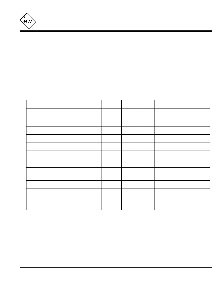
All values are for operation at 25∞C and a 5V supply, unless otherwise noted. For further information, refer to note 1 below.
Characteristic
Minimum
Typical
Maximum
Conditions
Units
Supply Voltage, V
DD
3.0
5.0
5.5
V
V
DD
rate of rise
0.05
V/ms
Average Supply Current, I
DD
1.0
2.4
mA
V
DD
= 5V
Notes:
1. This integrated circuit is produced with a Microchip Technology Inc.'s PIC12C5XX as the core embedded
microcontroller. For further device specifications, and possibly clarification of those given, please refer to the
appropriate Microchip documentation.
2. This spec must be met in order to ensure that a correct power on reset occurs. It is quite easily achieved
using most common types of supplies, but may be violated if one uses a slowly varying supply voltage, as
may be obtained through direct connection to solar cells, or some charge pump circuits.
3. This IC is uses CMOS technology so input currents to the logic are negligible. Each input does have internal
diode protection circuits, however, which may cause up to 1µA of leakage currents to flow.
4. Each of the values is graphically displayed in the Timing Diagrams on page 4.
5. During a mode change, the Dir input must remain stable for at least Tsu before any transition of Step.
Input low voltage
V
SS
0.15 V
DD
V
Input high voltage
V
DD
V
0.85 V
DD
Output low voltage
0.6
V
Output high voltage
V
V
DD
- 0.7
Current (sink) = 8.7mA
Current (source) = 5.4mA
see note 2
ELM310DSB
Delay Between Steps (Td)
Step Pulse Width (Tp)
µsec
10
-
- after a mode change (Td2)
µsec
30
-
µsec
50
-
see note 4
see note 4
see note 4
µsec
2
-
µsec
0
-
Direction Input Setup Time (Tsu)
Hold Time (Th)
see notes 4 & 5
see note 4
see note 3
see note 3
Step Inhibit on Power-up
10
20
30
msec
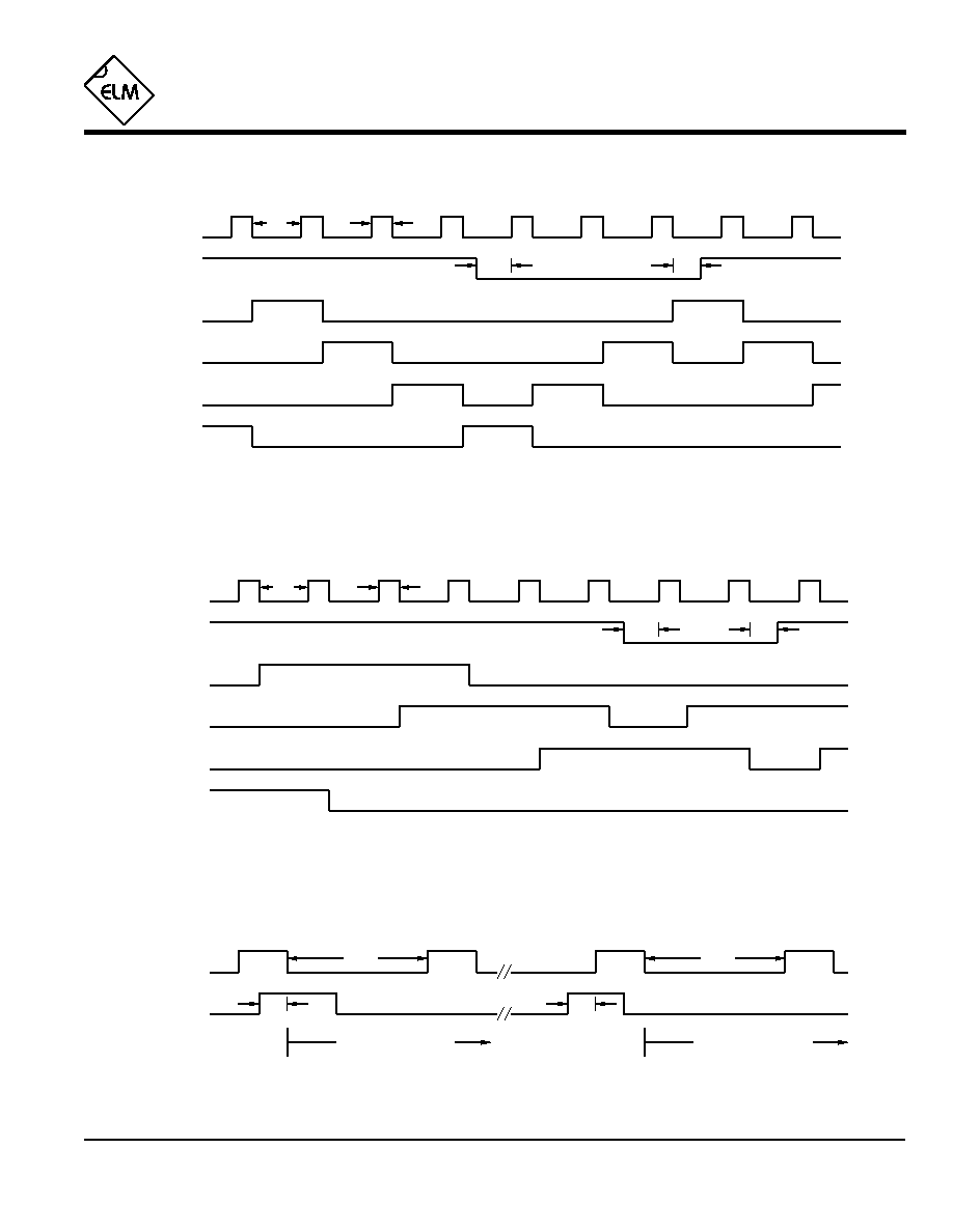
Timing Diagrams
4 of 5
ELM310
ELM310DSB
Elm Electronics ≠ Circuits for the Hobbyist
< http://www.elmelectronics.com/ >
Figure 1. Full Step Mode of Operation
Step
Dir
A
B
C
D
Figure 2. Half Step Mode of Operation
Figure 3. Changing the Mode of Operation
Step
Dir
Half Step Mode
Tsu
Th
Tp
Td
Step
Dir
A
B
C
D
Tsu
Th
Tp
Td
Tsu
Td2
Tsu
Full Step Mode
Td2
Example Application
5 of 5
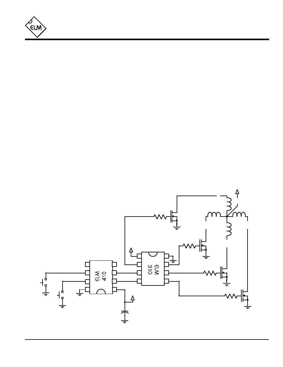
Figure 4. Manual Control of a Stepper Motor
Figure 4 shows the ELM310 used in a circuit to
control a four phase stepper motor. The motor shown
here is typical of the type often found in computer disk
drives, and are readily available on the surplus market.
This particular motor requires +12V at 160mA per phase
to operate, and has a resolution of 3.6∞ per step.
Momentary action pushbuttons are used as control
inputs in this case. This allows the user to experiment
with the operation of the motor. An ELM410 is used to
debounce the switches, so that the mechanical
bouncing of the switches does not cause multiple steps
of the motor armature.
Both integrated circuits are powered from a 5 volt
supply, not shown on this diagram. This supply could be
derived from the 12V for the motor, but is not
necessarily, as the user may want to separate the two
due to noise from the motor.
The motor is directly driven by IRF511 power
MOSFETS in this design, because they were readily
available, but many other devices would be suitable.
The main criteria, as well as voltage and current
capabilities, is that the MOSFET be fully switched by the
logic signal available (in this case 5V). Some of the
`logic level' HEXFETs would be well suited in this case
(IRLZ14 or IRL510 for example).
The main advantages of power MOSFETs over
bipolar types are their ability to be driven directly from
CMOS logic, and their inherent reverse biased diode
ELM310
ELM310DSB
2
3
4
6
5
+5V
8
1
0.1µF
+5V
Step
Clockwise
Elm Electronics ≠ Circuits for the Hobbyist
< http://www.elmelectronics.com/ >
1
2
3
4
8
7
6
5
Bk
R
G
Br
W
+12V
*
*
*
connected from Drain to Source internally. This diode
helps to control inductive kick-back when a winding is de-
energized. Optional resistors (50-100
) are shown in the
circuit to dampen resonances due to wiring inductance
and gate capacitance. They should be used if the
transistors are mounted any more than a few inches from
the ELM310.
Operation of the circuit is straight-forward. The motor
advances one step each time the step button is released.
If the clockwise input is also pressed, the windings will be
energized in the order A-B-C-D when in full-step mode,
and A-AB-B-BC-C-CD-D-DA in the half-step mode.
Recall that when power is first applied, no winding is
energized, to provide a means to sequence the start-up
of several motors in larger systems. For this reason, no
output will appear until the first step command is issued.
This circuit demonstrates the operation of a stepper
motor, and can easily be modified for further
experimentation. One change that could be made is the
addition of an oscillator in the place of the ELM410, to
provide continuous motion. Another might be the direct
connection of the ELM310 to a computer port for
robotics, and the incorporation of sensors for feedback to
the computer.
*
*
- see text
Stepper
Motor
7