 | –≠–ª–µ–∫—Ç—Ä–æ–Ω–Ω—ã–π –∫–æ–º–ø–æ–Ω–µ–Ω—Ç: ELM626DSA | –°–∫–∞—á–∞—Ç—å:  PDF PDF  ZIP ZIP |

ELM626
Elm Electronics ≠ Circuits for the Hobbyist
< http://www.elmelectronics.com/ >
Connection Diagram
PDIP and SOIC
(top view)
V
DD
V
SS
1
2
3
4
8
7
6
5
RS232 Break Detector
The ELM626 is a complete circuit for detecting
break signals on RS232 lines, in an 8 pin package.
The circuit is similar to the ELM627 except that an
output pulse is not generated on power-up.
The threshold for break signal detection is user
selectable, allowing the circuit to respond to a
transmitted null character, <ctrl>@, at various baud
rates. This provides a convenient means for the
remote triggering of this circuit by simply shifting to a
lower baud rate and sending a null byte.
Two complementary high current outputs are
provided by the ELM626, so that further buffering is
not usually required. The output signal can be
selected to be either a continuous one (following the
TxD input line) or else a 100ms pulse output.
No external components are required for circuit
operation other than possibly a current limiting
resistor, as all timing references are generated
internally.
∑ Low power CMOS design - typically 1mA at 5V
∑ No external timing elements required
∑ Complementary outputs
∑ Digitally controlled threshold timing
∑ Selectable output duration
∑ High current drive outputs - up to 25 mA
∑ Remote resetting of RS232 devices
∑ Edge triggered one-shot circuits
∑ Digitally controlled sequencing schemes
∑ Watchdog type signal monitors
TxD
T1
T0
Q
Description
Applications
Block Diagram
1 of 4
Features
ELM626DSA
P/C
Q
2
3
4
6
7
Programmable
Timer
Output
Logic
TxD
T1
T0
Q
5
P/C
Q

ELM626
Elm Electronics ≠ Circuits for the Hobbyist
< http://www.elmelectronics.com/ >
Pin Descriptions
Ordering Information
These integrated circuits are available in either the 300 mil plastic DIP format, or in the 200 mil SOIC surface
mount type of package. To order, add the appropriate suffix to the part number:
300 mil Plastic DIP............................... ELM626P
200 mil SOIC..................................... ELM626SM
2 of 4
All rights reserved. Copyright ©1998 Elm Electronics.
Every effort is made to verify the accuracy of information provided in this document, but no representation or warranty can be
given and no liability assumed by Elm Electronics with respect to the accuracy and/or use of any products or information
described in this document. Elm Electronics will not be responsible for any patent infringements arising from the use of these
products or information, and does not authorize or warrant the use of any Elm Electronics product in life support devices and/or
systems. Elm Electronics reserves the right to make changes to the device(s) described in this document in order to improve
reliability, function, or design.
V
DD
(pin 1)
This pin is the positive supply pin, and should
always be the most positive point in the circuit.
Internal circuitry connected to this pin is used to
provide power on reset of the microprocessor, so
an external reset signal is not required. Refer to
the Electrical Characteristics section for further
information.
Q (pin 2)
This signal is driven to a logical high level when a
break signal is detected.
Q (pin 3)
This output signal is normally held at a high level,
and is driven low when a break signal is detected.
P/C (pin 4)
This is the pulse/continuous control input pin,
used to modify the behavior of the circuit output.
If at a logic high when a break signal is detected,
the output will consist of a single 100ms pulse.
Otherwise, the output will remain active
continuously until pin 5 returns to a logical low
level. The output duration will always be a
minimum of 10ms, however.
TxD (pin 5)
This is the monitored signal input, usually
connected directly to the RS232 Transmit Data
line through a suitable current limiting resistor.
This input employs Schmitt trigger logic so that
input waveshaping circuitry is not normally
required.
T1 (pin 6) and T0 (pin 7)
These are the threshold setting inputs. Logic
levels on these pins at the rising edge of TxD are
used to determine the required minimum duration
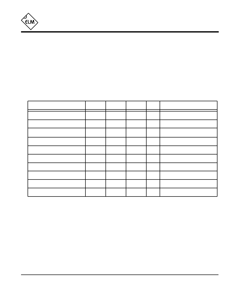
of the break signal, as shown in Table 1 below.
V
SS
(pin 8)
Circuit common is connected to this pin. This is
the most negative point in the circuit.
ELM626DSA
Threshold Setting
Min Break Signal
Baud rate, `00' character sent
will trigger at
but not at
T1
T0
(msec)
L
L
L
H
L
H
H
H
5.0
11
22
120
1200
2400
600
1200
300
600
-
110
Table 1. Threshold Settings
Elm Electronics ≠ Circuits for the Hobbyist
< http://www.elmelectronics.com/ >
ELM626
Electrical Characteristics
Absolute Maximum Ratings
Storage Temperature....................... -65∞C to +150∞C
Ambient Temperature with
Power Applied....................................-40∞C to +85∞C
Voltage on V
DD
with respect to V
SS
............ 0 to +7.5V
Voltage on any other pin with
respect to V
SS
........................... -0.6V to (V
DD
+ 0.6V)
Note:
Stresses beyond those listed here will likely damage
the device. These values are given as a design
guideline only. The ability to operate to these levels
is neither inferred nor recommended.
3 of 4
All values are for operation at 25∞C and a 5V supply, unless otherwise noted. For further information, refer to note 1 below.
Characteristic
Minimum
Typical
Maximum
Conditions
Units
Supply Voltage, V
DD
4.5
5.0
5.5
V
V
DD
rate of rise
0.05
V/ms
Average Supply Current, I
DD
1.0
2.4
mA
see note 3
Notes:
1. This integrated circuit is produced with a Microchip Technology Inc.'s PIC12C5XX as the core embedded
microcontroller. For further device specifications, and possibly clarification of those given, please refer to the
appropriate Microchip documentation.
2. This spec must be met in order to ensure that a correct power on reset occurs. It is quite easily achieved
using most common types of supplies, but may be violated if one uses a slowly varying supply voltage, as
may be obtained through direct connection to solar cells, or some charge pump circuits.
3. Device only. Does not include any LED or drive currents.
4. Pulse timing is generated internally, and is affected by both temperature and supply voltage. Although the
limits cannot be absolutely guaranteed, these are generally the widest variation that would normally be
encountered.
5. This specification represents current flowing through the protection diodes when applying large voltages to
the TxD input (pin 5) through a current limiting resistance. Currents quoted are the maximum continuous.
Input low voltage
V
SS
0.15 V
DD
V
Input high voltage
V
DD
V
0.85 V
DD
Output low voltage
0.6
V
Output high voltage
V
V
DD
- 0.7
Current (sink) = 8.7mA
Current (source) = 5.4mA
see note 2
ELM626DSA
Output Pulse Width
100
msec
Maximum Timing Error
5
%
see note 4
95
105
see note 4
Input Current
+0.5
mA
see note 5
-0.5

Example Application
4 of 4
Figure 1. Remote Reset Control
Figure 1 shows the ELM626 installed in a remotely
connected, RS232 linked device. This is typical of many
connections used today - a 9600 baud serial connection
is made between a PC and a remote device. Serial data
is continually sent between the two devices, but control
of the remote system is by software only.
It is often quite desireable in such a case to be able
to reset the remote system to a known state under
software control. This can be either at startup, or if the
remote system fails to respond to signals for any reason.
The circuit shown below represents all that is
typically required to provide remote resetting capability.
The ELM626 contiuously monitors the transmit data line
for a high level (3-25V) through the 100K
current
limiting resistor. The second 100K
resistor is only used
to provide a pull-down to V
SS
, should the data link
become open circuited. Depending on what other
devices are conected, this resistor may not be required.
Pins 6 and 7 are shown shorted to V
SS
, setting the
circuit to trigger on any high level that exceeds 5msec
in duration. This allows for triggering of the circuit on a
null character (`00') at 1200 baud, easily accomplished
with most systems.
The final connection to note is that the
pulse/continuous control (pin 4) has been tied to a high
level so that the generated reset pulse will always be of
100msec duration. This pulse width isn't normally
necessary for the circuitry, but may be desireable if one
wants to connect an LED or a buzzer to the circuit for
feedback.
Several variations on this type of circuit are
possible. By noting that the `reset' output can be used
for other control purposes, and possibly adding a toggle
type latch, the circuit can be expanded to remotely turn
on and off devices, leading to several automation
possibilities...
ELM626
ELM626DSA
Elm Electronics ≠ Circuits for the Hobbyist
< http://www.elmelectronics.com/ >
1
2
3
4
8
7
6
5
+5V
0.1µF
100K
to reset
circuitry
100K
9600 baud RS232 Link
TxD
RxD
SG
Host Computer
Remote System