 | –≠–ª–µ–∫—Ç—Ä–æ–Ω–Ω—ã–π –∫–æ–º–ø–æ–Ω–µ–Ω—Ç: ELM701SM | –°–∫–∞—á–∞—Ç—å:  PDF PDF  ZIP ZIP |

ELM701
Elm Electronics ≠ Circuits for the Hobbyist
< http://www.elmelectronics.com/ >
Connection Diagram
PDIP and SOIC
(top view)
V
DD
V
SS
Solid State Mouse
The ELM701 is a fun circuit for creating mouse-
like noises. Its very low current consumption makes
it an ideal candidate for battery-powered toys and
novelty items.
All of the logic required for circuit operation is
contained within this 8 pin integrated circuit.
Normally only a battery, a piezo element, and a
single resistor are all that are needed for a complete
circuit, although an on/off switch may be desireable.
The ELM701 uses pseudo-random number
generators to produce from one to four `chirps' at
random intervals of up to about eight seconds. This
makes the noises seem more like a real (but fairly
active) rodent. Between these series of chirps, the
circuit reverts to low power mode in order to
conserve battery energy.
1
2
3
4
8
7
6
5
Description
∑ Mousetrap bait
∑ Unique power on warning
∑ Voicing for toys
∑ Coffee machine or office desk item
∑ A fun plaything
Applications
Block Diagram
1 of 3
∑ Low power CMOS design
∑ Wide supply range - 3.0 to 5.5 volt operation
∑ Low power mode between chirps saves batteries
∑ Pseudo-random intervals for more realistic sounds
∑ Push-pull piezo drive eliminates the need for an
external capacitor while providing high volume
∑ Only one external resistor required
Features
ELM701DSB
OUT2
in4
OUT1
in2
in1
in3
7
6
Out1
Out2
Random
Interval
Timer
Random
Chirp
Generator
Output
Drivers

ELM701
Elm Electronics ≠ Circuits for the Hobbyist
< http://www.elmelectronics.com/ >
Pin Descriptions
Ordering Information
These integrated circuits are available in either the 300 mil plastic DIP format, or in the 200 mil SOIC surface
mount type of package. To order, add the appropriate suffix to the part number:
300 mil Plastic DIP............................... ELM701P
200 mil SOIC..................................... ELM701SM
2 of 3
Absolute Maximum Ratings
Storage Temperature....................... -65∞C to +150∞C
Ambient Temperature with
Power Applied....................................-40∞C to +85∞C
Voltage on V
DD
with respect to V
SS
............ 0 to +7.5V
Voltage on any other pin with
respect to V
SS
........................... -0.6V to (V
DD
+ 0.6V)
Note:
Stresses beyond those listed here will likely damage
the device. These values are given as a design
guideline only. The ability to operate to these levels
is neither inferred nor recommended.
All rights reserved. Copyright ©1999 Elm Electronics.
Every effort is made to verify the accuracy of information provided in this document, but no representation or warranty can be
given and no liability assumed by Elm Electronics with respect to the accuracy and/or use of any products or information
described in this document. Elm Electronics will not be responsible for any patent infringements arising from the use of these
products or information, and does not authorize or warrant the use of any Elm Electronics product in life support devices and/or
systems. Elm Electronics reserves the right to make changes to the device(s) described in this document in order to improve
reliability, function, or design.
V
DD
(pin 1)
This pin is the positive supply pin, and should
always be the most positive point in the circuit.
Internal circuitry connected to this pin is used to
provide power on reset of the microprocessor, so
an external reset signal is not required. Refer to
the Electrical Characteristics section for further
information.
in1, in2, in3, and in4
(pins 2, 3, 4, and 5 respectively)
These are CMOS input pins that are not used in
this design. Due to the nature of CMOS circuitry,
however, they can cause severe overheating,
and battery consumption is left floating. For this
reason all four of these pins must be connected
to either V
SS
or V
DD
.
OUT1 and OUT2 (pins 6 and 7)
These are the actual output piezo drive pins.
Polarity is not important for either the piezo
element or for the ELM701, but there must be a
series resistor installed in one of the
connections. This resistor both limits the volume
of the sound produced, and also limits the piezo
current on energization. (the piezo element
appears as a relatively large capacitive load, so
requires a means to limit the charging current).
See the Electrical Characteristics for resistor
sizes.
V
SS
(pin 8)
Circuit common is connected to this pin. This is
the most negative point in the circuit.
ELM701DSB
Elm Electronics ≠ Circuits for the Hobbyist
< http://www.elmelectronics.com/ >
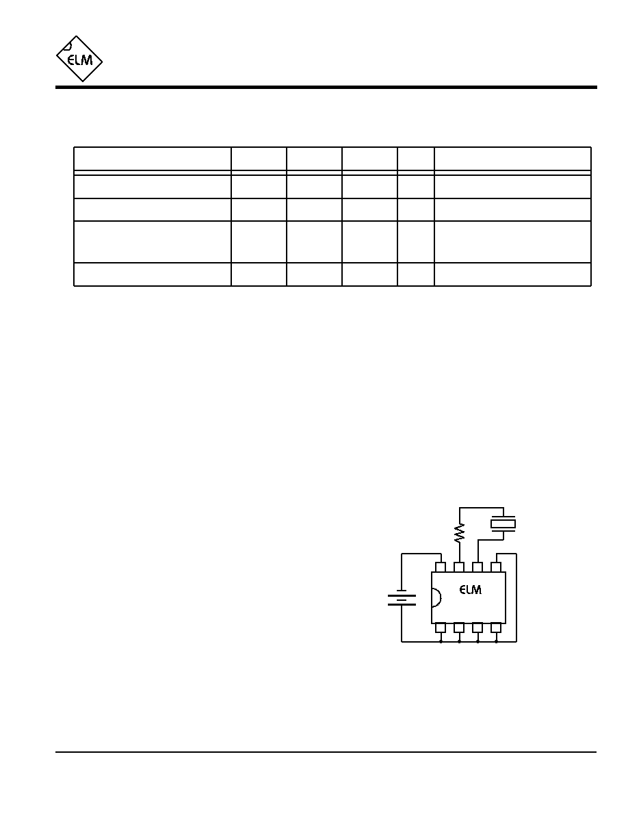
Example Application
ELM701
Electrical Characteristics
3 of 3
All values are for operation at 25∞C and a 3V supply, unless otherwise noted. For further information, refer to note 1 below.
Characteristic
Minimum
Typical
Maximum
Conditions
Units
Supply Voltage, V
DD
3.0
3.0
5.5
V
V
DD
rate of rise
0.05
V/ms
Average Supply Current, I
DD
0.60
2.0
mA
Notes:
1. This integrated circuit is produced with a Microchip Technology Inc.'s PIC12C5XX as the core embedded
microcontroller. For further device specifications, and possibly clarification of those given, please refer to the
appropriate Microchip documentation.
2. This spec must be met in order to ensure that a correct power on reset occurs. It is quite easily achieved
using most common types of supplies, but may be violated if one uses a slowly varying supply voltage, as
may be obtained through direct connection to solar cells, or some charge pump circuits.
3. Internal integrated circuit current only. This does not include the piezo element currents.
4. A series resistor must be used to limit the current peaks due to the relatively large capacitance (~50nF) of a
piezo element. Maximum size is determined by the desired volume level.
see note 2
ELM701DSB
The ELM701 is usually connected as
shown at the right. Pins 2 to 5 are simply connected
to the nearest supply pin so that they aren't left
floating, and a series resistor is connected in line
with one of the piezo connections.
For a permanent type of installation, it would be
a good idea to also connect a switch in series with
one of the battery leads. Although the chip has a lot
of initial appeal, you will probably want to be able to
disable it after a while. Making the batteries
accessible for easy removal is another method that
could be used.
2
14
µA
see note 4
Output Series Resistance
During operation, see note 3
Between chirps
4700
470
1
2
3
4
8
7
6
5
3V
+
4.7K
Piezo
Element
701