 | –≠–ª–µ–∫—Ç—Ä–æ–Ω–Ω—ã–π –∫–æ–º–ø–æ–Ω–µ–Ω—Ç: EM84520D | –°–∫–∞—á–∞—Ç—å:  PDF PDF  ZIP ZIP |

EM84520
2-IN-ONE SCROLLING MOUSE CONTROLLER
1
* This specification are subject to be changed without notice.
6.28.1999
Preliminary
Preliminary
Preliminary
Preliminary
Preliminary
GENERAL DESCRIPTION
The EM84520 Scrolling Mouse Controller is specially designed to control serial mouse or PS/2 mouse device.
This single chip can interface three key-switches and 4 X-Y photo-couples plus Z-axis directly to RS-232C or
8042 controller.
There are four types Z-axis inputs used to implement scrolling mouse functionality.
FEATURES
∑ Using 50k
±
1% resistor for RC oscillation.
∑ Compatible with legacy PS/2 mouse.
∑ Compatible with Microsoft serial scrolling mouse.
∑ Compatible with Microsoft PS/2 scrolling mouse.
∑ Serial or PS/2 port auto-detect.
∑ 100 bytes PnP ID code could be filled by code layer.
∑ Built-in noise immunity circuit.
∑ The sampiling rate of motion detector is up to 65KHz.
∑ Built-in three zener diodes : one in VDD to VSS, two in RTS to VDD.
∑ CMOS push-pull RXD output.
∑ Built-in current comparator for photo-couples input.
∑ Built-in three step dynamic input impedance.
∑ Three key-switches and four photo-couples inputs.
∑ RTS debouncing circuit included.
∑ Photo couple test mode included.
∑ Low power dissipation.
∑ Six types Z direction input:
1. Photo couples input. (Z/1)
4. Mechanical input. (Z/1)
2. Key-switches input.
5. Photo couples input. (Z/4)
3. Voltage-sensing input.
6. Mechanical input. (Z/2)
∑ Package type:
EM84520AP : 16DIP, Photo couples input. (Z/1) EM84520DP: 16DIP, Mechanical input. (Z/1)
EM84520BP : 16DIP, Key-switches input.
EM84520EP : 16DIP, Photo couples input. (Z/4)
EM84520CP : 16DIP, Voltage-sensing input.
EM84520FP : 16DIP, Mechanical input. (Z/2)
APPLICATION
∑ Serial PnP scrolling mouse.
∑ PS/2 scrolling mouse.
∑ Combo PnP scrolling mouse.
PIN ASSIGNMENT
V
DD
OSC.OUT
Z1
Z2
CLK/RTS
DATA/RXD
OPT
VSS
1
2
3
4
5
6
7
8
16
15
14
13
12
11
10
9
OSCR
Y2
Y1
X2
X1
L
M
R
EM84520A/B/C/D/E/F
EM84520
2-IN-ONE SCROLLING MOUSE CONTROLLER
2
* This specification are subject to be changed without notice.
6.28.1999
Preliminary
Preliminary
Preliminary
Preliminary
Preliminary
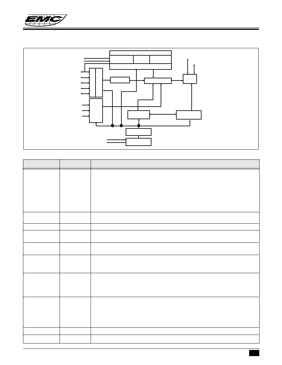
FUNCTIONAL BLOCK DIAGRAM
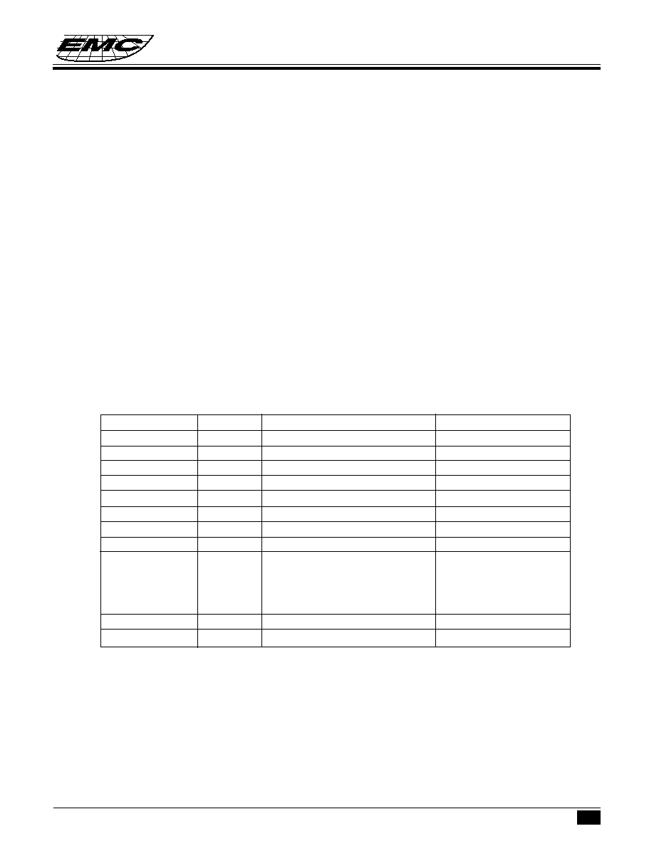
PIN DESCRIPTIONS
OPT
I/O
INPUT: 200kohm pull low to VSS.
When OPT is connected to VDD, EM84520 will enter test mode. In test mode,
L will be the output of X1,while M will be the output of X2. Toggling R key can
change these output to be Y1,Y2 or Z1,Z2 respectively.
OUTPUT: 2kHz Z-axis LED driving source with A/D/E/F version.
"1"= VDD, "0"= floating
High duty is about 60us.
OSC.OUT
O
The RC oscillation clock output. Or 3mA sink current output for X, Y photo
emitters.
OSCR
I
Connect 50k
±
1% precise resistor for oscillation.
CLK/RTS
I/O
Connect to 8042 auxiliary port CLK line in PS/2 mode or connect directly to RS-
232C RTS pin in serial mode. Auto-detect the operating port by this pin.
DATA/RXD
I/O
Connect to 8042 auxiliary port DATA line in PS/2 mode or connect directly to RS-
232C RXD pin in serial mode.
R
I
Three key-switches inputs. 200k
resistor pull low.
M
I/O
In Z-axis key mode, M key toggling can change the scrolling speed from low to
L
I/O
high.
X1
I
Three step dynamic input impedance. If OSC.OUT is not connected to LEDs, the
X2
I
dynamic input impedance will be off.
Y1
I
Use current comparator to measure photo-couples "ON", or "OFF".
Y2
I
Z1
I
Z-axis input.
Z2
I
Photo mode : Three steps dynamic input impedance. Current comparator input.
Key mode : 200 k
resistor pull low. 7 levels increased by "M" key.
Voltage mode : 200 k
resistor pull low. 7 levels voltage comparator.
Mechanical mode : 13.2k
resistor pull low. Current comparator input.
VSS
Negative power.
VDD
Power line.
Symbol
I/O
Function
Z1
Z2
OPT
X1
X2
Y1
Y2
L
M
R
OSCR
OSC.OUT
C
O
M
P
A
R
A
T
O
R
M
O
T
I
O
N
D
E
T
E
C
T
O
R
D
E
B
O
U
N
C
E
COUNTER
COMMAND
STATUS
SYSTEM CLOCK
GENERATOR
RC
OSCILLATION
MULTIPLEXER
DATA
I/O
TIMING
CONTROLLER
COMPARATOR VOLTAGE
SENSOR
KEY-SWITCH
DETECTOR
Z-AXIS COUNTER
THREE TYPES SELECTOR
DATA/RXD
CLK/RTS
EM84520
2-IN-ONE SCROLLING MOUSE CONTROLLER
3
* This specification are subject to be changed without notice.
6.28.1999
Preliminary
Preliminary
Preliminary
Preliminary
Preliminary
FUNCTION DESCRIPTIONS
(I) Serial Scrolling Mouse :
In Microsoft mode, the transmission cycle consists of four bytes in one report. Each byte contains one start
bit, 7 data bits and two stop bits. The first byte contains "L", "R" key status and four bits of the two most
significant bits in horizontal counter and vertical counter. The second byte represents the value accumulated
by horizontal counter, the third byte is the data of the vertical counter. The last byte contains "M" key status
and Z-axis value. The vertical data is transmitted in 2's complement.
Output byte arrange
Bit no.
......
6
5
4
3
2
1
0
1st byte
......
1
L
R
V7'
V6'
H7
H6
2nd byte
....
0
H5
H4
H3
H2
H1
H0
3rd byte
....
0
V5'
V4'
V3'
V2'
V1'
V0'
4th byte
....
0
0
M
Z3
Z2
Z1
Z0
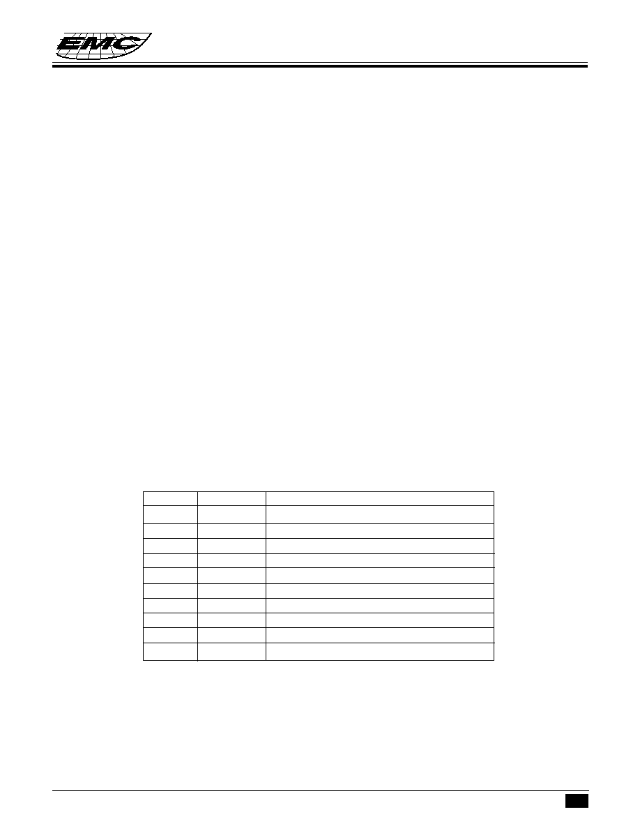
Plug & Play ID code
When RTS input from low to high, EM84520 will send a string ID code. Customer can specify the contains
of the code area and the total lenth below 100 bytes by changing the code layer.
Field Name
Length
Field Data
Description
Other ID
<17
4D, 5A, 40, 00, 00, 00
ID for legacy
Begin ID
1
08
Begin PnP ID
PnP Revision
2
01, 24
Version 1.00
EISA ID
3
25, 2D, 23
EMC
Product ID
4
10, 10, 10, 11
0001
Serial Number
9
3C
None provided
Class ID
<34
3C, 2D, 2F, 35, 33, 25
Mouse Class
Driver ID
<42
3C, 30, 2E, 30, 10 26, 10, 21
PnP0F0A
User Name
<42
3C, 25, 2D, 23, 00, 33, 23, 32,
EMC SCROLLING
2F, 2C, 2C, 29, 2E, 27, 00, 33,
SERIAL MOUSE
25, 32, 29, 21, 2C, 00, 2D, 2F,
35, 33, 25
Check sum
2
21, 15
2 bytes checks um
End PnP
1
09
End PnP ID
(II) Legacy PS/2 mouse operating:
(A) Operating mode
There are four operating modes in PS/2 mouse:
a. Reset Mode:
In this mode a self-test is initiated during power-on or by a Reset command. After reset signal, PS/2 mouse
will :
(a) Send completion code AA & ID code 00.
(b) Set default :
EM84520
2-IN-ONE SCROLLING MOUSE CONTROLLER
4
* This specification are subject to be changed without notice.
6.28.1999
Preliminary
Preliminary
Preliminary
Preliminary
Preliminary
sampling rate: 100 reports/s
non-autospeed
stream mode
2 dot/count
disable
b. Stream Mode:
The maximum rate of transfer is the programmed sample rate.
Data report is transmitted if
(a) switch is pressed
(b) movement has been detect
c. Remote Mode:
Data is transmitted only in response to a Read Data command.
d. Wrap Mode:
Any byte of data sent by the system, except hex EC ( Reset wrap mode ) or hex FF ( Reset ), is returned
by EM84520.
B). PS/2 Mouse Data Report:
a). In stream mode: A data report is sent at the end of a sample interval.
b). In remote mode: A data report is sent in response to Read Data command.
c). Data report format:
Byte
Bit
Description
1
0
Left button status; 1 = pressed
1
Right button status; 1 = pressed
2
Middle button status; 1 = pressed
3
Reserve
4
X data sign; 1 = negative
5
Y data sign; 1 = negative
6
X data overflow; 1 = overflow
7
Y data overflow; 1 = overflow
2
0-7
X data ( D0 - D7 )
3
0-7
Y data ( D0 - D7 )
EM84520
2-IN-ONE SCROLLING MOUSE CONTROLLER
5
* This specification are subject to be changed without notice.
6.28.1999
Preliminary
Preliminary
Preliminary
Preliminary
Preliminary
C) PS/2 mouse Data Transmission:
a). EM84520 generates the clocking signal when sending data to and receiving data from the system.
b). The system requests EM84520 receive system data output by forcing the DATA line to an inactive level
and allowing CLK line to go to an active level.
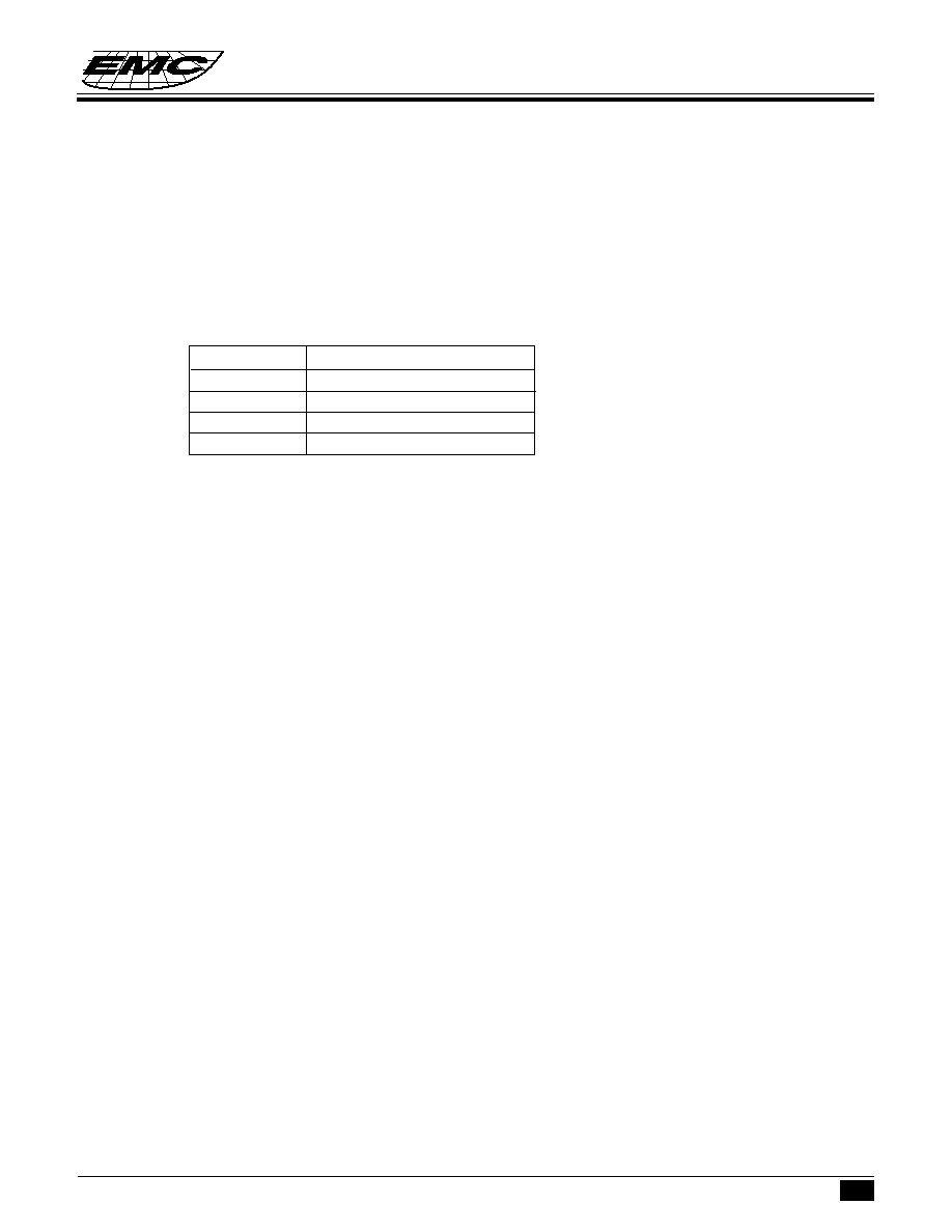
c). Data transmission frame:
Bit
Function
1
Start bit ( always 0 )
2-9
Data bits ( D0 - D7 )
10
Parity bit ( odd parity )
11
Stop bit ( always 1 )
d). Data Output ( data from EM84520 to system ):
If CLK is low ( inhibit status ) , data is no transmission.
If CLK is high and DATA is low ( request-to-send ), data is updated. Data is received from the system
and no transmission are started by EM84520 until CLK and DATA both high. If CLK and DATA both
are high, the transmission is ready. DATA is valid prior to the falling edge of CLK and beyond the rising edge
of CLK. During transmission, EM84520 check for line contention by checking for an inactive level on CLK
at intervals not to exceed 100u sec. Contention occurs when the system lowers CLK to inhibit EM84520
output after EM84520 has started a transmission. If this occurs before the rising edge of the tenth clock,
EM84520 internal store its data in its buffer and returns DATA and CLK to an active level. If the contention
does not occur by the tenth clock, the transmission is complete.
Following a transmission, the system inhibits EM84520 by holding CLK low until it can service the input
or until the system receives a request to send a response from EM84520.
e). Data Input ( from system to EM84520 ):
The system first check if EM84520 is transmitting data. If EM84520 is transmitting, the system can override
the output forcing CLK to an inactive level prior to the tenth clock. If EM84520 transmission is beyond
the tenth clock, the system receives the data. If EM84520 is not transmitting or if the system choose to
override the output, the system force CLK to an inactive level for a period of not less than 100
µ
sec while
preparing for output. When the system is ready to output start bit (0), it allows CLK go to active level. If
request-to-send is detected, EM84520 clocks 11 bits. Following the tenth clock EM84520 checks for
an active level on the DATA line, and if found, force DATA low , and clock once more. If occurs framing
error, EM84520 continue to clock until DATA is high, then clocks the line control bit and request a
Resend. When the system sends out a command or data transmission that requires a response, the system
waits for EM84520 to response before sending its next output.
D). PS/2 Mouse Error Handling:
a). A Resend command ( FE ) following receipt of an invalid input or any input with incorrect parity.
b). If two invalid input are received in succession, an error code of hex (FC) is send to the system.