Document Outline
- ˛ˇ
- ˛ˇ
- ˛ˇ
- ˛ˇ
- ˛ˇ
- ˛ˇ
- ˛ˇ
- ˛ˇ
- ˛ˇ
- ˛ˇ
- ˛ˇ
- ˛ˇ
- ˛ˇ
- ˛ˇ
- ˛ˇ
- ˛ˇ
- ˛ˇ
- ˛ˇ
R
EM4223
Copyright
© 2004, EM Microelectronic-Marin SA
1
www.emmicroelectronic.com
Read-only UHF Radio Frequency Identification Device
according to ISO IEC 18000-6
Description
The EM4223 chip is used in UHF passive read-only
transponder applications. The chip derives its operating
power from an RF beam transmitted by the reader, which
is received and rectified by the chip. It transmits its
factory-programmed code back to the reader by varying
the amount of energy that is reflected from the chip
antenna circuit (passive backscatter modulation).
The air interface communication protocol is implemented
according to ISO18000-6 type A.
The code structure supports the effort of EPCglobal, Inc.
as an industry accepted standard.
It additionally incorporates the Fast Counting
SupertagTM protocol for applications where the fast
counting of large tag populations is required.
The chip is frequency agile, and can be used in the
range of 800 MHz to 2.5GHz for RF propagating field
applications.
Typical Applications
Supply chain management (SCM)
Tracking and tracing
Asset control
Licensing
Auto-tolling
Key words
ISO 18000-6A
UHF
EPCTM data structure
Fast SupertagTM
Features
Air interface is ISO18000-6 type A compliant
Supports EAN∑UCC and EPCTM data structures as
defined by the Auto-ID center
Supports Fast Counting SupertagTM mode
128 bit user memory license plate Group select by
means of `Application Family Identifier' (AFI)
according to ISO
Fast reading of user data during arbitration (no need
to first take an inventory)
Specific command set for supply chain logistics
support.
Frequency independent: Typically used at 862 - 870
MHz, 902 - 950 MHz and 2.45 GHz
Low voltage operation - down to 1.0 V
Low power consumption
Cost effective
-40 to +85∞C operating temperature range
Benefits
Numbering scheme according to international
standards
Operates worldwide according to the local radio
regulation
Ideal for applications where long range and high-
speed item identification is required
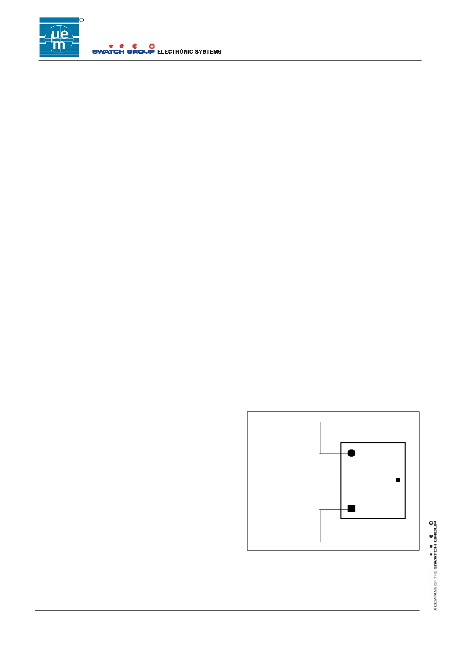
Typical Operating Configuration
Fig. 1
Chip design is a joint development with RFIP Solutions Ltd
Connect pad A+
And V
SS
to a
dipole antenna
A+
EM4223
V
DD
V
SS
EM MICROELECTRONIC -
MARIN SA

R
EM4223
Copyright
© 2005, EM Microelectronic-Marin SA
2
www.emmicroelectronic.com
Table of contents
READ-ONLY UHF RADIO FREQUENCY
IDENTIFICATION DEVICE ACCORDING TO
ISO IEC 18000-6.................................................
0H0H
1
Description ..................................................................
1H1H
1
Typical Applications ....................................................
2H2H
1
Key words ...................................................................
3H3H
1
Benefits .......................................................................
4H4H
1
TABLE OF CONTENTS .....................................
5H5H
2
Absolute Maximum Ratings ........................................
6H6H
3
Handling Procedures ..................................................
7H7H
3
Operating Conditions ..................................................
8H8H
3
Block Diagram.............................................................
9H9H
3
Electrical Characteristics.............................................
10H10H
4
Timing Characteristics ................................................
11H11H
4
1.
GENERAL DESCRIPTION.................................
12H12H
5
2.
FUNCTIONAL DESCRIPTION ...........................
13H13H
5
General Command Format .........................................
14H14H
6
Supported Command set ............................................
15H15H
6
3.
BASIC COMMAND FORMATS..........................
16H16H
6
Short commands.........................................................
17H17H
6
Extended commands ..................................................
18H18H
6
Implied MUTE command (Fast Supertag Mode only) .
19H19H
7
Command state transitions .......................................
20H20H
11
4.
GENERAL REPLY FORMAT ...........................
21H21H
14
5.
FORWARD LINK ENCODING - READER TO
TRANSPONDER ..............................................
22H22H
15
Carrier modulation pulses .........................................
23H23H
15
Basic time interval ≠ definition of "Tari" .....................
24H24H
15
Data coding...............................................................
25H25H
16
Data Frame format....................................................
26H26H
16
Data decoding...........................................................
27H27H
17
Bits and byte ordering ...............................................
28H28H
17
Reader to Transponder 5 bit CRC (CRC-5) ..............
29H29H
17
Command Decoder...................................................
30H30H
17
6.
RETURN LINK DATA ENCODING -
TRANSPORTER TO READER ........................
31H31H
18
Return link data encoding .........................................
32H32H
18
Return link preamble.................................................
33H33H
19
Cyclic Redundancy Check (CRC) .............................
34H34H
19
7.
MEMORY ORGANISATION AND
CONFIGURATION INFORMATION .................
35H35H
19
Memory Map .............................................................
36H36H
19
Unambiguous User Data (UUD) & SUID...................
37H37H
19
AFI ............................................................................
38H38H
20
Personality Block ......................................................
39H39H
20
8.
TRANSPONDER SELECTION OPERATION ≠
INIT_ROUND AND BEGIN_ROUND
COMMANDS.....................................................
40H40H
21
INIT_ROUND COMMAND SELECTION OPERATION
..................................................................................
41H41H
21
BEGIN_ROUND COMMAND SELECTION
OPERATION .............................................................
42H42H
22
9.
COMMANDS AND STATES............................
43H43H
23
Commands ...............................................................
44H44H
23
Tag States................................................................
45H45H
23
Tag state storage .....................................................
46H46H
24
10.
COLLISION ARBITRATION............................
47H47H
25
General explanation of the collision arbitration
mechanism ...............................................................
48H48H
25
FST SYSTEMS ........................................................
49H49H
25
FST MODE OPTIONS..............................................
50H50H
26
Use of the round_size function (ISO & FST modes).
51H51H
27
Ordering Information ................................................
52H52H
29
Versions ...................................................................
53H53H
29
R
EM4223
Copyright
© 2005, EM Microelectronic-Marin SA
3
www.emmicroelectronic.com
Absolute Maximum Ratings
Parameter Symbol
Min
Max
Supply Voltage
V
DD
≠ V
SS
(V)
Storage temperature (∞C)
RMS supply current pad A (mA)
V
DD
T
store
-0.3
-50
+3.6
+150
10
Table 1
Stresses above these listed maximum ratings may cause
permanent damages to the device. Exposure beyond
specified operating conditions may affect device reliability or
cause malfunction.
Handling Procedures
This device has built-in protection against high static
voltages or electric fields; however, anti-static precautions
must be taken as for any other CMOS component. Unless
otherwise specified, proper operation can only occur when
all terminal voltages are kept within the voltage range.
Unused inputs must always be tied to a defined logic
voltage level.
Operating Conditions
Parameter Symbol
Min
Max
Unit
Supply voltage
V
DD
1.0 3.5
V
Operating Temperature
T
A
-40 +85 ∞C
Table 2
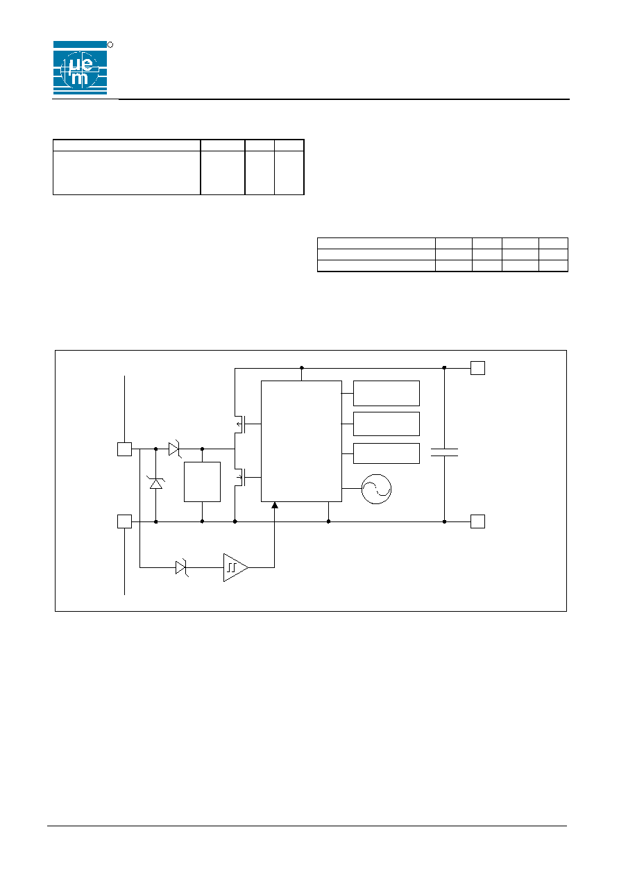
Block Diagram
LOGIC
PON
V
DD
V
SS
CS
Limit
Data
extractor
Ant
OSC
AFI
ROM 8b
Data
ROM 128b
V
SS
Fig. 2

R
EM4223
Copyright
© 2005, EM Microelectronic-Marin SA
4
www.emmicroelectronic.com
Electrical Characteristics
V
DD
= 2.0V, T
A
=+25∞C, unless otherwise specified
Parameter Symbol Conditions
Min.
Typ.
Max.
Unit
Operating voltage
V
DD
≠ V
SS
V
ponf
3.5 V
Current consumption
I
S
V
DD
-V
SS
= 1.5 V
2.0
3.9
uA
Power On Reset Rising
V
ponr
1.2
V
Power On Reset Fall
V
ponf
1.0
V
Electrostatic discharge
HBM to MIL-STD-
883 method 3015
V
DD
and V
SS
pad
A+ pad
1.5
0.5
KV
KV
Internal oscillator
frequency
Fo
sc
Over full temperature range
192
320
448
KHz
Input series Impedance
@900MHz
R
in
C
in
V
DD
≠ V
SS
< 1V
19
0.620
pF
Modulation depth
decoding
At typical pulse width
27 %
100 %
%
Table 3
Timing Characteristics
Over full voltage and temperature range, unless otherwise specified
Parameter
Symbol
Conditions
Min.
Typ.
Max.
Unit
Forward Link
(Reader to Transponder)
average
33
kbps
Pulse width
T
pw
100% modulation depth
6
10
14
uS
Pulse interval Data 0
T
pi0
100% modulation depth
12
20
28
uS
Pulse interval Data 1
T
pi1
100% modulation depth
24
40
56
uS
Return Link
(Transponder to Reader)
(note 1)
nominal at 25∞C as selected by
factory programmed Personality Bit
40
or
160
kbps
Bit rate accuracy
short term (note 2)
During a message transmission
+/- 1
%
Bit rate accuracy
long term @1.5V
of nominal 40kb/s
+/- 15
%
Reply
to Receive
turn-around time
2
Bit
times
Receive to
Reply
turn-around time
Depends on Transponders chosen
reply slot
150
uS
Tag Command window
T
cw
Opens at the start of the 3
rd
bit
clock period after the end of the
last bit transmitted by the
Transponder to the reader. Closes
in the middle of the 5
th
bit clock
period.
Note 1: V
DD
= 2.0V, T
A
=+25∞C
Note 2: V
DD
= 2.0V
Table 4

R
EM4223
Copyright
© 2005, EM Microelectronic-Marin SA
5
www.emmicroelectronic.com
1. GENERAL
DESCRIPTION
The EM4223 is a monolithic integrated circuit transponder
for use in UHF passive backscatter RFID applications.
Operating power for the transponder circuit is derived
from the illuminating RF field of an RFID Reader by
means of an on-chip virtual battery rectifier circuit.
A user specified license plate or tag identifier is factory
programmed into the transponder by means of laser
trimming. This data is communicated to the reader by
means of backscatter modulation of the illuminating RF
carrier wave.
The EM4223 supports both the ISO18000-6 type A and
the Fast Supertag
TM (FST) Protocols. The EM4223 may
be configured to wake-up in either of these modes
according to user requirements. Once active, the
transponder will automatically respond to either protocol
(and eventually switch modes) on receipt of the
appropriate commands.
2. FUNCTIONAL
DESCRIPTION
When a Transponder is placed in the RF energising field
of a Reader it powers up. When the power supply has
reached the correct operating voltage, the Configuration
Register is loaded with the contents of the three pre-
programmed personality flags. Depending on the state of
these wake-up flags, the Transponder will be placed in
either ISO 18000-6 Type A (ISO) or Fast Supertag (FST)
mode and in one of three states: READY, ACTIVE or
ROUND_STANDBY. After this process is complete the
Transponder is able to receive commands and to transmit
data to the Reader.
The Transponder is half-duplex and is thus in either
receive mode (default) or transmit mode. When not
actively transmitting messages to the Reader on the
Return Link, the Transponder will wait for the start of a
new command, which will be detected as a quiet period of
specific duration, followed by a valid Start Of Frame
(SOF) symbol (see
54H54H
Fig. 11). The Transponder requires
the quiet period in order to ensure that it does not detect
partial transmissions by a reader as a valid command.
This can occur if a transponder enters the field of a reader
and powers up part through a reader transmission. The
received SOF symbol is used to calibrate the command
decoder every time a command is received. This
calibration is used to establish a pivot to distinguish
between subsequent data `0' and data `1' symbols. Each
time that a new command is received by the Transponder,
the SOF re-calibrates the decode counter thereby
compensating for any variation in the Transponder clock
frequency due to changes in RF excitation levels or
temperature variations. The circuit has been designed to
accommodate a Transponder clock frequency variation of
+/-40% from nominal. When the Transponder is
transmitting the receive circuitry is disabled.
All commands received from the Reader will have an
immediate effect on the Transponder. In addition, certain
commands will have a persistent effect. The possible
immediate effects are one or both of the following:
A change of State (see
55H55H
Fig. 19)
A Data Message sent to the Reader.
The possible persistent effects are:
Data Messages to the Reader will contain SUID (as
described later in this section) or Data Messages to
the Reader will contain USER DATA of 128 bits,
The Round Size (Number of Slots) over which all of
the Transponders in the population will spread their
Data Messages to the Reader will be configured.
The Transponder will switch between ISO and FST
modes of operation (as described below).
A sub-population of Transponders will be enabled to
send Data Messages to the Reader dependent on
either the AFI or on all or a portion of the USER
DATA of 128 bits.
The start of a command from the Reader has a special
significance if a Transponder is operating in the FST
mode and is in the ROUND_ACTIVE state. When the
falling edge of the first symbol of a command (SOF) is
received by a Transponder in the ROUND_ACTIVE state
while in FST mode, it will immediately move to the
ROUND_STANDBY state. If a command is successfully
received, the Transponder will move back to the
ROUND_ACTIVE state. If the Transponder does not
receive a valid command it will remain in the
ROUND_STANDBY state until a valid command has been
received. This enables the Reader to silence all
Transponders that have not already started sending their
Data Messages to the Reader in compliance with the FST
protocol. It is important to note that the Reader does not
have to send a full command or indeed even a part of a
command, as long as it sends a low going pulse of
approximately Ω Tari (Type A Reference Interval Time)
duration.
An important feature of this transponder is its ability to
switch seamlessly between ISO mode and FST mode
whatever its "wake up" personality setting, depending only
on the mode or characteristics of the controlling reader. A
Transponder that "wakes up" in the ISO mode on power-
up will switch to the FST mode if it receives a
Wake_Up_FST command. Similarly, a Transponder that
"wakes up" in the FST mode on power-up will switch to
the ISO mode if it receives an INIT-ROUND, INIT-
ROUND-ALL or BEGIN-ROUND command.