 | ÐлекÑÑоннÑй компоненÑ: EM65XX | СкаÑаÑÑ:  PDF PDF  ZIP ZIP |
Äîêóìåíòàöèÿ è îïèñàíèÿ www.docs.chipfind.ru
EM65XX
Copyright
©
2005, EM Microelectronic-Marin SA
1
www.emmicroelectronic.com
EM65XX Datasheet
MFP versions of EM66XX
(Mask Rom)
EM Microelectronic-Marin SA
Tel +41 32 755 51 11
Fax +41 32 755 54 03
http:
//
www.emmicroelectronic.com
EM MICROELECTRONIC -
MARIN SA

EM65XX
Copyright
©
2005, EM Microelectronic-Marin SA
2
www.emmicroelectronic.com
Table of Contents
1. GENERAL ........................................................................................................................ 3
ORDERING INFORMATION.................................................................................................. 3
2. EM6503 ............................................................................................................................ 4
3. EM6504 ............................................................................................................................ 7
4. EM6505 .......................................................................................................................... 11
5. EM6517 .......................................................................................................................... 15
6. EM6520 .......................................................................................................................... 16
7. EM6521 .......................................................................................................................... 17
8. EM6522 .......................................................................................................................... 18
9. EM6540 .......................................................................................................................... 19
10. PACKAGE
DIMENSIONS ........................................................................................... 23
11. ORDERING
INFORMATION ....................................................................................... 28
EM65XX
Copyright
©
2005, EM Microelectronic-Marin SA
3
www.emmicroelectronic.com
1. General
The EM65xx is the Multiple Field Programmable Version of the corresponding EM66xx 4 bit
Microcontroller
The program ROM is replaced by non volatile memory, which can be programmed up to 100 times.
Functionally, the two types are equal, except the metal options which are defined in the following
pages.
Electrically, the MFP `s work above 2.0V and need more current, see the tables in the following
description.
The programming is done with the EM MFP programmer, either by putting the device onto the
programmer or connecting it with the connector at the back to your board.
Handling Procedures
This devices have built-in protection against high static voltages or electric fields; however, anti-static
precautions should be taken as for any other CMOS component.
Unless otherwise specified, proper operation can only occur when all terminal voltages are kept within
the supply voltage range.
Absolute maximum ratings
Min.
Max.
Units
Power supply VDD-VSS
- 0.2
+ 5.5
V
Input voltage
VSS - 0.2
VDD+0.2
V
Storage temperature
- 40
+ 125
°C
Electrostatic discharge to
MIL-STD-883C method 3015
-2000
+2000
V
Maximum soldering conditions
10s x 250°C
Stresses above these listed maximum ratings may cause permanent damage to the device. Exposure beyond
specified electrical characteristics may affect device reliability or cause malfunction.
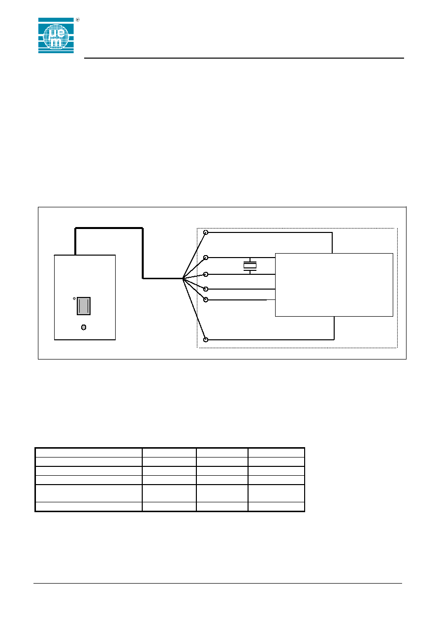
Ordering Information
The MFP's should be used for engineering purposes only. No volume production must be planned.
EM65xx
Qin
Vdd
Qout
Test
Vreg
Vss
EM MFP
Programmer
Your
PCB
EM65XX
Copyright
©
2005, EM Microelectronic-Marin SA
4
www.emmicroelectronic.com
2. EM6503
Input/Output ports
All ports if selected as outputs are Push-pull outputs (driving high / low).
Inputs are not blocked when Output is selected and Outputs comes Hi-Z in Sleep mode.
Input/Output Port Options
Pull-Up
Yes / No
Pull-Down
Yes / No
Nch-open drain
Yes / No
Input blocked
when Output
Yes / No
Output Hi-Z in
SLEEP mode
Yes / No
0
1
4
5
6
A0 PA0
input
NO
NO
A1 PA1
input
NO
NO
A2 PA2
input
NO
NO
A3 PA3
input
NO
NO
B0 PB0
In/Out
NO
NO
NO
NO
YES
B1 PB1
In/Out
NO
NO
NO
NO
YES
B2 PB2
In/Out
NO
NO
NO
NO
YES
B3 PB3
In/Out
NO
NO
NO
NO
YES
C0 PC0
In/Out
NO
NO
NO
NO
YES
C1 PC1
In/Out
NO
NO
NO
NO
YES
C2 PC2
In/Out
NO
NO
NO
NO
YES
C3 PC3
In/Out
NO
NO
NO
NO
YES
D0 PD0
In/Out
NO
NO
NO
NO
YES
D1 PD1
In/Out
NO
NO
NO
NO
YES
D2 PD2
In/Out
NO
NO
NO
NO
YES
D3 PD3
In/Out
NO
NO
NO
NO
YES
PortA reset
No PortA reset option is selected
NO PortA reset
combination
PA0 & PA1 logic
AND input reset
PA0 & PA1 & PA2
logic AND input
reset
PA0 & PA1 & PA2 &
PA3 logic AND input
reset
0
1
2
3
RA PortA
RESET
X
Supply Voltage Level Detector
T= -10°C to 60°C
Symb. Parameter
Min. Typ. Max. Unit
VSVLD1
SVLD voltage Level1
2.25 2.5 2.75 V
VSVLD2
SVLD voltage Level2
3.15 3.5 3.85 V
VSVLD3
SVLD voltage Level3
3.87 4.3 4.73 V
EM65XX
Copyright
©
2005, EM Microelectronic-Marin SA
5
www.emmicroelectronic.com
Electrical specifications
Standard Operating Conditions
Parameter
Value
Description
Temperature
0°C...+60°C
VDD
+2.0 ...+5.0V
VSS
0 V (reference)
CVreg
min. 100nF
Vreg logic supply capacitor
fq
32768 Hz
nominal frequency
Rqs
35 kOhm
typical quartz serial resistor
CL
8.2pF
typical quartz load capacitance
df/f
+/- 30 ppm
quartz frequency tolerance
DC characteristics - Power Supply Pins
VDD=3.0V, T=25°C (note4) (unless otherwise specified), Vreg not shorted to VDD
Parameter
Conditions
Symb.
Min.
Typ.
(note1)
Max.
Unit
ACTIVE Supply Current
+25°C (note2)
IVDDa
9.0
15.0
µA
ACTIVE Supply Current
(in active mode)
(note2) (note3)
0°C...+60°C
IVDDa
20.0
µA
STANDBY Supply Current
+25°C
IVDDh
1.7
4.0
µA
STANDBY Supply Current
(in Halt mode)
(note3)
0°C...+60°C
IVDDh
7.0
µA
SLEEP Supply Current
+25°C
IVDDs
0.7
2.0
µA
SLEEP Supply Current
(SLEEP =1)
(note3)
0°C...+60°C
IVDDs
5.0
µA
Regulated Voltage
0°C...+60°C
Vreg
1.6
2.5
V
VDD=5.0V, T=25°C (note4) (unless otherwise specified), Vreg not shorted to VDD
Parameter
Conditions
Symb.
Min.
Typ.
(note1)
Max.
Unit
ACTIVE Supply Current
+25°C (note2)
IVDDa
13.0
18.0
µA
ACTIVE Supply Current
(in active mode)
(note2) (note3)
0°C...+60°C
IVDDa
20.0
µA
STANDBY Supply Current
+25°C
IVDDh
1.8
5.0
µA
STANDBY Supply Current
(in Halt mode)
(note3)
0°C...+60°C
IVDDh
10.0
µA
SLEEP Supply Current
+25°C
IVDDs
0.7
2.0
µA
SLEEP Supply Current
(SLEEP =1)
(note3)
0°C...+60°C
IVDDs
5.0
µA
Note1: For current measurement typical quartz described in Operating Conditions is used.
All I/O pins without internal Pull Up/Down are pulled to VDD externally.
Note2: Test loop with successive writing and reading of two different addresses with an inverted
values (five instructions should be reserved for this measurement),
Note3: NOT tested at temperature if delivered in chip form.
Note4: Test conditions for ACTIVE and STANDBY Supply current mode are: Qin = external
square wave, from rail to rail of Vreg (regulated voltage) with 100nF capacitor on Vreg.
fQin = 33kHz.
Document Outline
- Table of Contents
- þÿ
- þÿ
- þÿ
- þÿ
- þÿ
- þÿ
- þÿ
- þÿ
- þÿ
- þÿ
- þÿ
- þÿ