EME66xx
Hardware Description
Copyright © 2005, EM Microelectronic-Marin SA
3
www.emmicroelectronic.com
1.
EM66xx Emulator hardware description......................................................................................................4
1.1.
Warning ....................................................................................................................................................4
1.2.
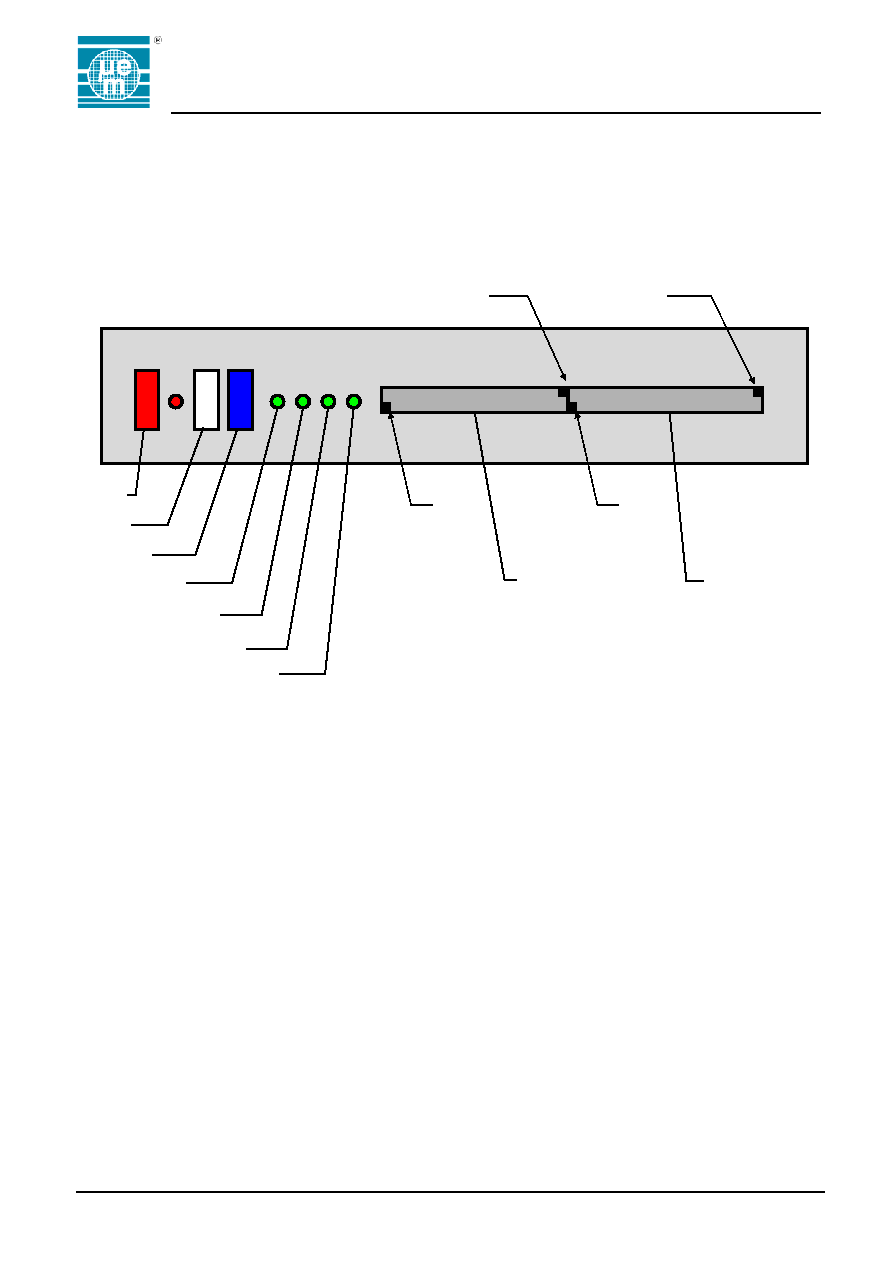
Front panel ...............................................................................................................................................5
1.2.1.
ICE connector pin-out .......................................................................................................................6
1.2.2.
LCD Connector pin-out ** .................................................................................................................6
1.3.
Rear Panel ...............................................................................................................................................7
1.4.
Switch settings .........................................................................................................................................8
2.
General operational points........................................................................................................................ 12
2.1.
Using external clock .............................................................................................................................. 12
2.2.
Option Registers ................................................................................................................................... 12
2.3.
Watchdog timers ................................................................................................................................... 12
2.4.
Synchronous and asynchronous modes............................................................................................... 12
3.
Configuration resistors.............................................................................................................................. 13
3.1.
Port Configuration ................................................................................................................................. 13
3.2.
Pull-up and Pull-down Resistor placement. .......................................................................................... 14
4.
Default configurations ............................................................................................................................... 15
4.1.
EM66xx ................................................................................................................................................. 15
4.2.
EM6603 / EM6605 ................................................................................................................................ 16
4.3.
EM6604 ................................................................................................................................................. 17
4.4.
EM6607 ................................................................................................................................................. 18
4.5.
EM6617 ................................................................................................................................................. 19
4.6.
EM6620 ................................................................................................................................................. 20
4.7.
EM6621, EM6622, EM6625, EM6626 ................................................................................................. 21
4.8.
EM6640 ................................................................................................................................................. 22
4.9.
EM6680 ................................................................................................................................................. 23
5.
EM66xx emulator upgrade procedure ...................................................................................................... 24

EME66xx
Hardware Description
Copyright © 2005, EM Microelectronic-Marin SA
4
www.emmicroelectronic.com
1.
EM66xx Emulator hardware description
1.1. Warning
When connecting or disconnecting the EM66xx emulator to the target system or when connecting
headers or LCD's to the connectors on the front panel it is essential that the emulator is powered off.
Failure to do this could result in damage to the emulator hardware, which would require the system
being returned to EM Microelectronic for repair.
Please also be aware that when Port pins are set to input, any voltage greater that the V I/O level that
has been set (See Below) can also damage the emulator. This includes transitory switching spikes as
well as sustained over voltage conditions. It is recommended that any high levels driven onto the
emulator port pins for sustained periods should be set to approximately 10 percent below the set V I/O
level. So for example, if V I/O is set to 3.0V then to drive a high on to PortB the recommended level
would be around 2.7V. Alternatively V I/O can be set above the switching level applied to the emulator
to say 3.3V in the above example.