 | –≠–ª–µ–∫—Ç—Ä–æ–Ω–Ω—ã–π –∫–æ–º–ø–æ–Ω–µ–Ω—Ç: B32671 | –°–∫–∞—á–∞—Ç—å:  PDF PDF  ZIP ZIP |

Film Capacitors
Metallized Polypropylene Film Capacitors (MKP)
Series/Type:
B32671 ... B32672
Date:
August 2004
© EPCOS AG 2004. Reproduction, publication and dissemination of this data sheet, enclosures hereto and the
information contained therein without EPCOS' prior express consent is prohibited.
Purchase orders are subject to the General Conditions for the Supply of Products and Services of the Electrical
and Electronics Industry recommended by the ZVEI (German Electrical and Electronic Manufacturers' Associ-
ation), unless otherwise agreed.

Typical applications
Electronic ballasts (resonant circuits)
SMPS
High-frequency AC loads
Pulse circuits
Climatic
Max. operating temperature: 125
∞
C
Climatic category (IEC 60068-1): 55/110/56
Construction
Dielectric: metallized polypropylene (PP)
Wound capacitor technology
Plastic case (UL 94 V-0)
Epoxy resin coating
Features
Very high AC voltages for all frequency
ranges
Very small dimensions
High peak voltage for short time periods
High peak current
High pulse withstand capability
Terminals
Parallel wire leads, lead-free tinned
Special lead lengths available on request
Marking
Manufacturer's logo, lot number, type number,
rated capacitance (coded),
capacitance tolerance (code letter),
rated AC voltage, date of manufacture (coded)
Delivery mode
Bulk (untaped)
Taped (Ammo pack or reel)
For notes on taping, refer to chapter "Taping and packing".
Dimensional drawing
Dimensions in mm
Lead spacing
±
0.4
Lead diameter
d
1
Type
10
0.6
B32671
15
0.8
B32672
Metallized polypropylene film capacitors (MKP)
B32671 ... B32672
High VAC, high temperature (wound)
2

Overview of available types
Lead spacing 10 mm
15 mm
Type
B32671
B32672
Page
4
5
V
rms
(VAC)
500
600
600
700
V
R
(VDC)
1000
1600
1600
2000
C
R
(nF)
1.0
1.2
1.5
2.2
2.7
3.3
3.9
4.10
4.7
5.6
6.2
6.8
8.2
10
12
15
22
33
B32671 ... B32672
High VAC, high temperature (wound)
3
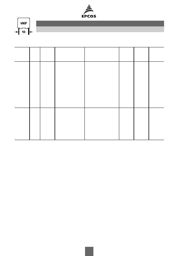
Ordering codes and packing units (lead spacing 10 mm)
V
rms
f
1 kHz
VAC
V
R
VDC
C
R
nF
Max. dimensions
w
◊
h
◊
l
mm
Ordering code
(composition see
below)
Ammo
pack
pcs./unit
Reel
pcs./unit
Untaped
pcs./unit
Further E series and intermediate capacitance values on request.
Composition of ordering code
+ =
Capacitance tolerance code:
*** = Packaging code:
M =
±
20%
K =
±
10%
J =
±
5%
A =
±
3.5%
H =
±
2.5%
289 = Ammo pack
189 = Reel
000 = Untaped (lead length 6
1 mm)
500
1000
3.3
4.0
◊
9.0
◊
13.0
B32671L0332+***
1000
1700
1000
3.9
4.0
◊
9.0
◊
13.0
B32671L0392+***
1000
1700
1000
4.1
4.0
◊
9.0
◊
13.0
B32671L0412+***
1000
1700
1000
4.7
4.0
◊
9.0
◊
13.0
B32671L0472+***
1000
1700
1000
5.6
5.0
◊
11.0
◊
13.0
B32671L0562+***
830
1300
1000
6.2
5.0
◊
11.0
◊
13.0
B32671L0622+***
830
1300
1000
6.8
5.0
◊
11.0
◊
13.0
B32671L0682+***
830
1300
1000
8.2
5.0
◊
11.0
◊
13.0
B32671L0822+***
830
1300
1000
10
6.0
◊
12.0
◊
13.0
B32671L0103+***
680
1100
1000
12
6.0
◊
12.0
◊
13.0
B32671L0123+***
680
1100
1000
600
1600
1.2
4.0
◊
9.0
◊
13.0
B32671L1122+***
1000
1700
1000
1.5
5.0
◊
11.0
◊
13.0
B32671L1152+***
830
1300
1000
2.2
5.0
◊
11.0
◊
13.0
B32671L1222+***
830
1300
1000
2.7
5.0
◊
11.0
◊
13.0
B32671L1272+***
830
1300
1000
3.3
6.0
◊
12.0
◊
13.0
B32671L1332+***
680
1100
1000
3.9
6.0
◊
12.0
◊
13.0
B32671L1392+***
680
1100
1000
4.1
6.0
◊
12.0
◊
13.0
B32671L1412+***
680
1100
1000
B32671
High VAC, high temperature (wound)
4
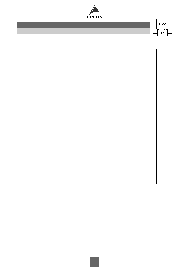
Ordering codes and packing units (lead spacing 15 mm)
V
rms
f
1 kHz
VAC
V
R
VDC
C
R
nF
Max. dimensions
w
◊
h
◊
l
mm
Ordering code
(composition see
below)
Ammo
pack
pcs./unit
Reel
pcs./unit
Untaped
pcs./unit
Further E series and intermediate capacitance values on request.
Composition of ordering code
+ =
Capacitance tolerance code:
*** = Packaging code:
M =
±
20%
K =
±
10%
J =
±
5%
A =
±
3.5%
H =
±
2.5%
289 = Ammo pack
189 = Reel
000 = Untaped (lead length 6
1 mm)
600
1600
6.2
5.0
◊
10.5
◊
18.0
B32672L1622+***
1170
1300
1000
6.8
5.0
◊
10.5
◊
18.0
B32672L1682+***
1170
1300
1000
8.2
6.0
◊
11.0
◊
18.0
B32672L1822+***
960
1100
1000
10
6.0
◊
11.0
◊
18.0
B32672L1103+***
960
1100
1000
12
6.0
◊
12.0
◊
18.0
B32672L1123+***
960
1100
1000
15
7.0
◊
12.5
◊
18.0
B32672L1153+***
830
900
1000
22
8.5
◊
14.5
◊
18.0
B32672L1223+***
680
700
500
33
9.0
◊
17.5
◊
18.0
B32672L1333+***
640
700
500
700
2000
1.0
5.0
◊
10.5
◊
18.0
B32672L8102+***
1170
1300
1000
1.2
5.0
◊
10.5
◊
18.0
B32672L8122+***
1170
1300
1000
1.5
5.0
◊
10.5
◊
18.0
B32672L8152+***
1170
1300
1000
2.2
5.0
◊
10.5
◊
18.0
B32672L8222+***
1170
1300
1000
2.7
5.0
◊
10.5
◊
18.0
B32672L8272+***
1170
1300
1000
3.3
5.0
◊
10.5
◊
18.0
B32672L8332+***
1170
1300
1000
3.9
5.0
◊
10.5
◊
18.0
B32672L8392+***
1170
1300
1000
4.1
5.0
◊
10.5
◊
18.0
B32672L8412+***
1170
1300
1000
4.7
5.0
◊
10.5
◊
18.0
B32672L8472+***
1170
1300
1000
5.6
6.0
◊
11.0
◊
18.0
B32672L8562+***
960
1100
1000
6.2
6.0
◊
11.0
◊
18.0
B32672L8622+***
960
1100
1000
6.8
6.0
◊
11.0
◊
18.0
B32672L8682+***
960
1100
1000
8.2
6.0
◊
12.0
◊
18.0
B32672L8822+***
960
1100
1000
10
7.0
◊
12.5
◊
18.0
B32672L8103+***
830
900
1000
12
8.5
◊
14.5
◊
18.0
B32672L8123+***
680
700
500
15
8.5
◊
14.5
◊
18.0
B32672L8153+***
680
700
500
22
9.0
◊
17.5
◊
18.0
B32672L8223+***
640
700
500
B32672
High VAC, high temperature (wound)
5
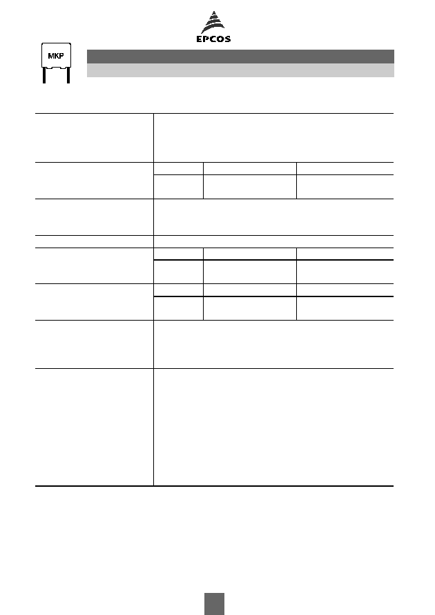
Technical data
Operating temperature range
Max. operating temperature T
op,max
+125
∞
C
Upper category temperature T
max
+110
∞
C
Lower category temperature T
min
55
∞
C
Rated temperature T
R
+85
∞
C
Dissipation factor tan
(in 10
-3
) at
Typical
Upper limit
at 20
∞
C
10 kHz
0.3
0.6
(upper limit values)
100 kHz
0.3
1.0
Insulation resistance R
ins
> 100 G
at 20
∞
C, rel. humidity
65%
(minimum as-delivered values)
DC test voltage
1.6
V
R
, 2 s
Category voltage V
C
T
A
(
∞
C)
DC voltage derating
AC voltage derating
(continuous operation with V
DC
T
A
85
V
C
= V
R
V
C,rms
= V
rms
or V
AC
at f
1 kHz)
85<T
A
110
V
C
= V
R
(165 T
A
)/80
V
C,rms
=V
rms
(165 T
A
)/80
Operating voltage V
op
for
T
A
(
∞
C)
DC voltage (max. hours) AC voltage (max. hours)
short operating periods
T
A
100
V
op
= 1.25
V
C
(2000 h) V
op
= 1.0
V
C,rms
(2000 h)
(V
DC
or V
AC
at f
1 kHz)
100<T
A
125 V
op
= 1.25
V
C
(1000 h) V
op
= 1.0
V
C,rms
(1000 h)
Damp heat test
56 days/40
∞
C/93% relative humidity
Limit values after damp
Capacitance change
C/C
2%
heat test
Dissipation factor change
tan
1.0
10
-3
(at 1 kHz)
Insulation resistance R
ins
50 G
Reliability:
Failure rate
1 fit (
1
10
-9
/h) at 0.5
V
R
, 40
∞
C
Service life t
SL
200 000 h at 1.0
V
R
, 40
∞
C
For conversion to other operating conditions and temperatures,
refer to chapter "Quality assurance", page .
Failure criteria:
Total failure
Short circuit or open circuit
Failure due to variation
Capacitance change
C/C
> 10%
of parameters
Dissipation factor tan
> 4
upper limit values
Insulation resistance R
ins
< 1500 M
B32671 ... B32672
High VAC, high temperature (wound)
6
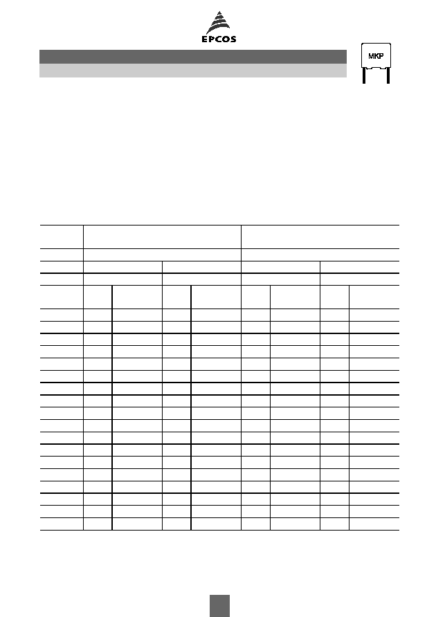
Pulse handling capability
"dV/dt" represents the maximum permissible voltage change per unit of time for non-sinusoidal
voltages, expressed in V/
µ
s.
"k
0
" represents the maximum permissible pulse characteristic of the waveform applied to the
capacitor, expressed in V
2
/
µ
s.
Note:
The values of dV/dt and k
0
provided below must not be exceeded in order to avoid damaging the
capacitor.
dV/dt and k
0
values
Lead
spacing
10 mm
15 mm
Type
B32671
B32672
V
rms
(VAC)
500
600
600
700
V
R
(VDC)
1000
1600
1600
2000
C
R
nF
dV/dt
V/
µ
s
k
0
V
2
/
µ
s
dV/dt
V/
µ
s
k
0
V
2
/
µ
s
dV/dt
V/
µ
s
k
0
V
2
/
µ
s
dV/dt
V/
µ
s
k
0
V
2
/
µ
s
1.0
6 500
10 000 000
1.2
6 000
14 400 000
6 250
9 700 000
1.5
5 600
14 000 000
6 000
9 500 000
2.2
5 200
13 800 000
5 000
9 200 000
2.7
5 000
13 600 000
4 750
9 000 000
3.3
4 700
16 000 000
4 700
13 300 000
4 500
8 900 000
3.9
4 300
13 600 000
4 500
13 100 000
4 000
8 300 000
4.1
4 100
12 300 000
4 400
13 000 000
3 800
8 000 000
4.7
3 800
9 900 000
3 600
7 800 000
5.6
3 400
8 400 000
3 300
7 400 000
6.2
3 200
7 700 000
3 600
18 600 000
3 100
7 200 000
6.8
3 100
7 400 000
3 500
17 400 000
3 000
7 000 000
8.2
2 700
7 200 000
3 100
15 400 000
2 800
6 700 000
10
2 500
7 000 000
2 800
13 800 000
2 600
6 300 000
12
2 300
6 400 000
2 600
12 600 000
2 400
6 000 000
15
2 300
12 300 000
2 200
5 900 000
22
2 000
11 800 000
1 900
5 300 000
33
1 700
11 000 000
B32671 ... B32672
High VAC, high temperature (wound)
7
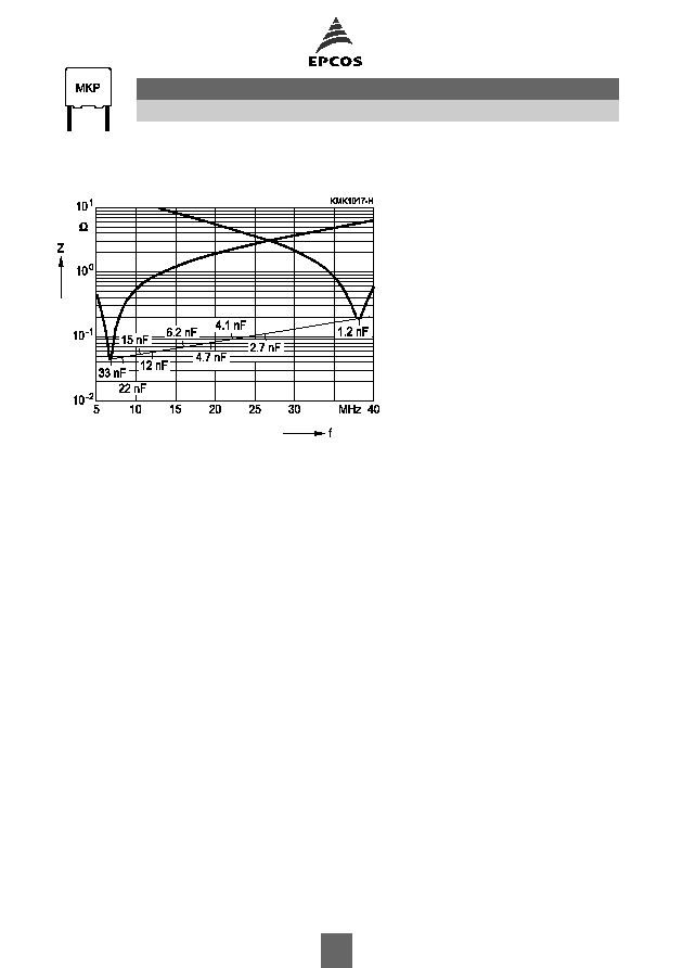
Impedance Z versus frequency f
(typical values)
B32671 ... B32672
High VAC, high temperature (wound)
8
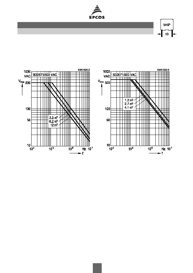
Permissible AC voltage V
rms
versus frequency f (for sinusoidal waveforms T
A
100
∞
C)
For T
A
>100
∞
C, please refer to "General technical information", section 3.2.3.
Lead spacing 10 mm
500 VAC/1000 VDC
600 VAC/1600 VDC
B32671
High VAC, high temperature (wound)
9

Permissible AC voltage V
rms
versus frequency f (for sinusoidal waveforms T
A
100
∞
C)
For T
A
>100
∞
C, please refer to "General technical information", section 3.2.3.
Lead spacing 15 mm
600 VAC/1600 VDC
700 VAC/2000 VDC
B32672
High VAC, high temperature (wound)
10

Operation at overvoltages during heating and ignition of lamps (T
A
40
∞
C)
In lighting applications, the capacitors can be subjected to overvoltages during the heating and ig-
nition periods. An overvoltage occurs when the operation voltage exceeds the permissible AC
voltage at the resonant frequency f
r
.
For a repetitive application of on/off switching pulses (as for example in the life tests applied by
electronic ballast manufacturers), limits have to be imposed on the time periods under over-
voltage and on the duty cycle, in order to keep the capacitance value within the required margins:
The overvoltage time t
OV
should be less than 1 sec.
The maximum duty cycle of the overvoltage is given by
where V
rms,ov
is the RMS voltage during period t
OV
.
and V
rms
is the permissible AC voltage for continuous operation at the resonant frequency f
r
(given by the "permissible AC voltage versus frequency f" graphics in theprevious pages).
The drift of capacitance depends on the V
pp
attained, and the total time under overvoltage,
which is calculated in hours as follows:
(N
i
t
OV
) / 3600
where N
i
is the number of overvoltage impulses and t
OV
is expressed in seconds.
The maximum drift of capacitance as a function of both parameters is provided graphically in the
following pages.
B32671 ... B32672
High VAC, high temperature (wound)
11
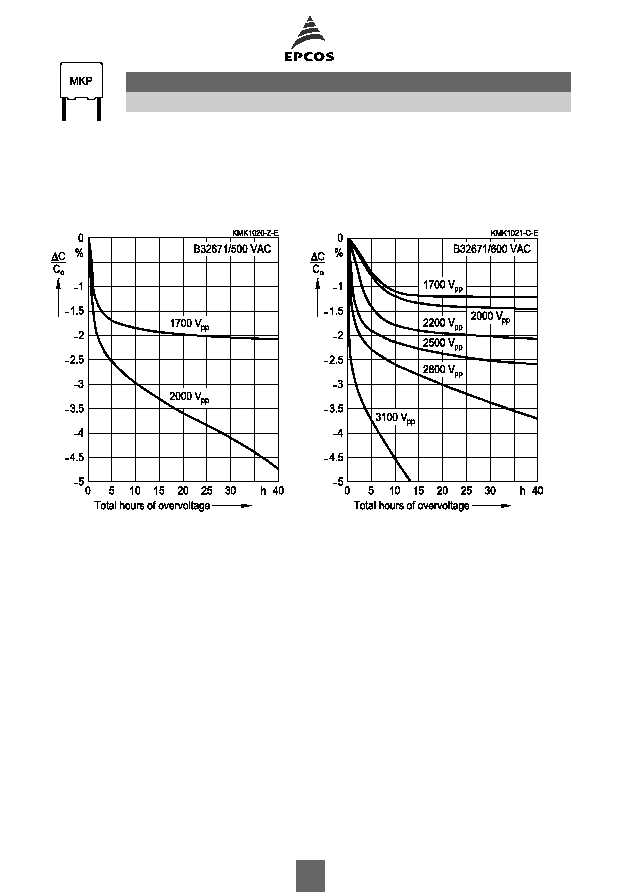
Estimation of the maximum drift of capacitance value in function of the number of total
hours overvoltage
Lead spacing 10 mm
500 VAC/1000 VDC
600 VAC/1600 VDC
B32671 ... B32672
High VAC, high temperature (wound)
12

Estimation of the maximum drift of capacitance value in function of the number of total
hours overvoltage
Lead spacing 15 mm
600 VAC/1600 VDC
700 VAC/2000 VDC
B32671 ... B32672
High VAC, high temperature (wound)
13