
Switching Spark Gap
FS08X-1JG
Ordering code:
B88069X3560T502
KB AB E / KB AB PM
Issue 05, 16.06.2004
Page 1 of 2
Nominal breakdown voltage V
N
800 V
Initial values
2)
Static breakdown voltage V
S
1)
First ignition value V
S, FTE
after 24 hours in darkness
Following ignition values V
S, FIV
950
704 ... 896
V
V
Electrical life time
3)
Breakdown voltage V
B
First ignition value V
B, FTE
after 24 hours in darkness
Ignition time t
I
at V
0
during life
Following ignition values V
B, FIV
1000
60
680 ... 920
V
ms
V
Switching
operations
at ≠40 ∞C
at +25; 125; 150 ∞C
40 000
200 000
Ignitions
Ignitions
Test circuit parameters
Open circuit voltage V
0
Loading resistance R
Discharge capacitance C
Inductance
L
Discharge peak current I
P
1000
68
100
0.5
~ 400
V
k
nF
µH
A
General technical data
Max. static breakdown voltage at 100 kV/s
Insulation resistance at 100 V
Early ignition values below 680 V
Breakdown
time
Maximum switching frequency
Maximum loading current
Weight
1300
> 100
1
50
400
50
~ 2
V
M
%
ns
Hz
mA
g
Marking, blue
800 WWY O
800
- Nominal voltage
WW
- Calendar week of production
Y
- Year of production
O
- Non radioactive
1)
At delivery AQL 0,65 level II, DIN ISO 2859
2)
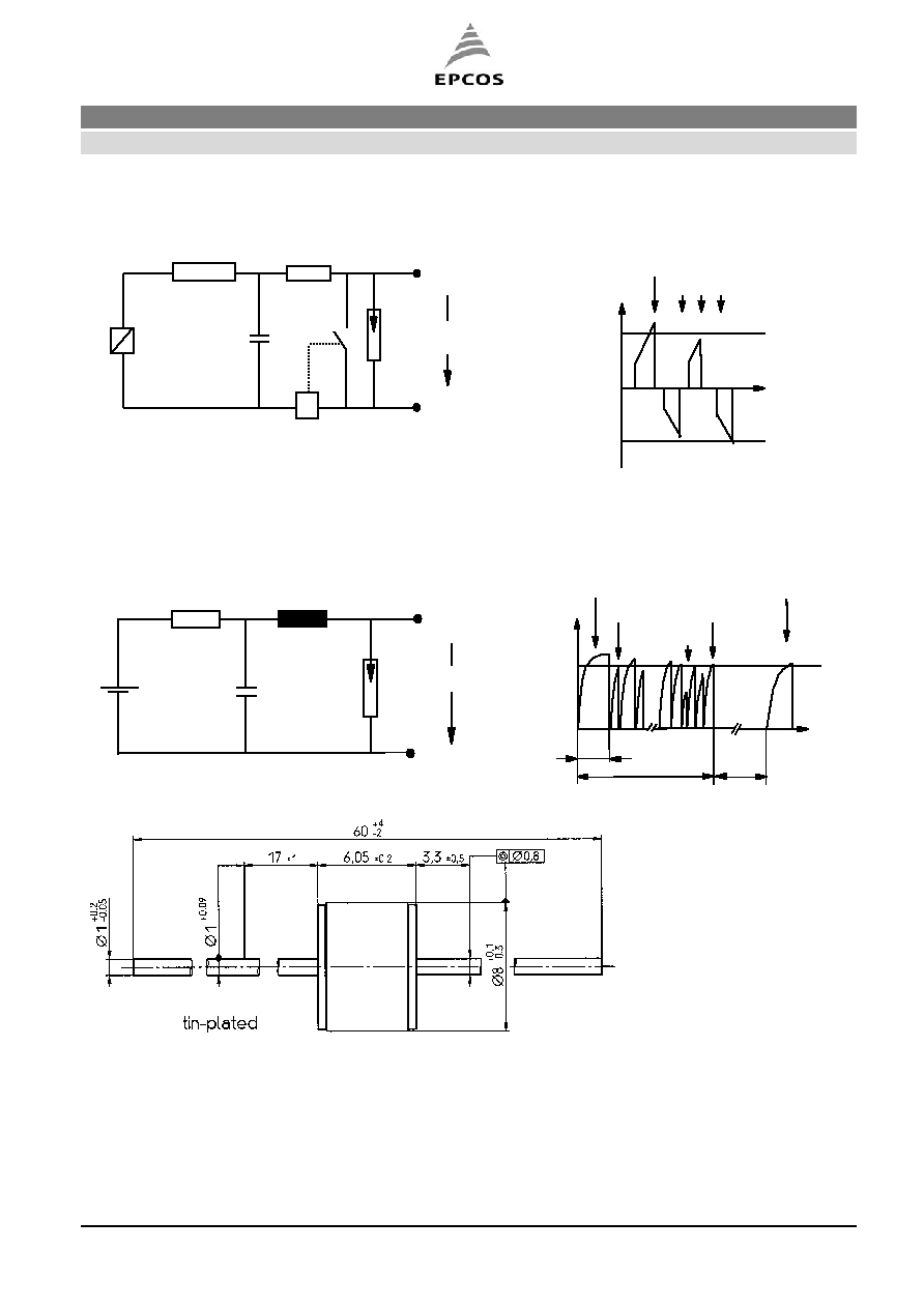
Page 2, Fig. 1 and 2
3)
Page 2, Fig. 3 and 4
Switching Spark Gap
FS08X-1JG
Ordering
code:
B88069X3560T502
EPCOS AG 2002. Reproduction, publication and dissemination of this data sheet, enclosures hereto and the information
contained therein without EPCOS' prior express consent is prohibited.
Purchase orders are subject to the General Conditions for the Supply of Products and Services of the Electrical and
Electronics Industry recommended by the ZVEI (German Electrical and Electronic Manufacturers' Association), unless
otherwise agreed.
KB AB E / KB AB PM
Issue 05, 16.06.2004
Page 2 of 2
Not to scale
Dimensions in mm
Non controlled document
Fig. 4: Explanation of measurands
Fig. 3: QC- test circuit (sampling inspection at 25 ∞C)
DUT
L
C
V
O
R
V
B
V
N
10 s
1 s
t
I
Early ignition
V
B, FTE
V
B, FTE
Range of V
B, FIV
V
B
t
Fig. 1: QC- test circuit (100% outgoing inspection)
Fig. 2: Explanation of measurands
DUT
ICU
0,22
µF
51k
I = const
V
S
DUT device under test
ICU
ignition control unit (sensitivity 10 .. 30
µA)
Discharge current 10 ≠ 20 mA
V
S, FTE
V
S
V
N
- V
N
V
S, FIV
dV
S
/dt ~ dV
N
/dt
t