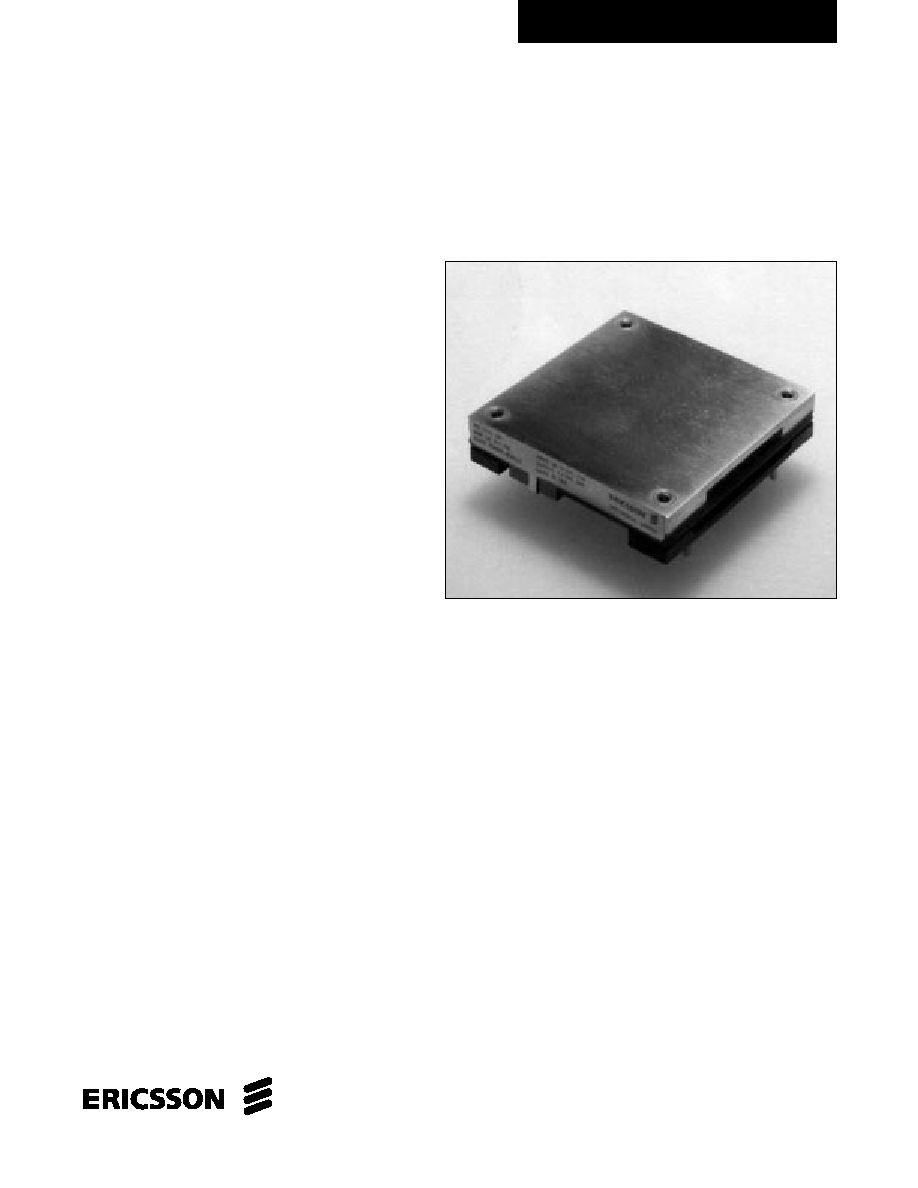
PKL 4118 PIT
/
PKL 4918 PIT
Advanced Specification
50-60A DC/DC Power Modules
48V Input, 1.8V Output
∑ High efficiency 87% Typ (60A) at full load
∑ High power density, 37.2 W/in
3
, (1.8V @ 60A)
∑ Fast dynamic response, 200µs,
+
- 200 mVpeak Typ
∑ Low output ripple, 80 mVp-p Typ
∑ Parallelable with no external components
∑ Wide input voltage range (36-75V)
∑ 1,500Vdc isolation voltage
∑ Max case temperature +100∫C
∑ Designed to meet UL 1950 and EN 60950
The PKL series represents another one of Ericsson's "industry
first" achievements in the continued development of our "Third
Generation" of high-density, high-efficiency power modules.
This module packs 37.2 W/in
3
at 87% efficiencies (1.8V @
60A) in an industry standard footprint that has been enhanced to
include two additional output pins for motherboard connection
reliability. These breakthrough features come from using the most
advanced patented topology utilizing integrated magnetics and
synchronous rectification on a low-resistivity multilayer PCB.
This product features fast dynamic response times and low
output ripple, which are important parameters when supplying
low-voltage logics. The PKL series also is especially suited for
limited board space and high dynamic load applications.
Ericsson's PKL Power Module has been designed with the
converging "New Telecoms" market in mind, by specifying
the input voltage range in accordance with ETSI specifications.
The PKL series also offers over-voltage protection, under-volt-
age protection, over-temperature protection, soft-start, and is
short circuit proof.
These modules are manufactured on highly automated
manufacturing lines. Ericsson's world-class quality commitment
is reflected in our standard five-year warranty. Ericsson
Microelectronics has been an ISO 9001 certified supplier
since 1991.
For a complete product program, please reference the back cover.

Characteristics
Conditions
min
typ max
Unit
VI
Input voltage
36
75
Vdc
range
VIoff
Turn-off input
Ramping from
31
33
Vdc
voltage
higher voltage
VIon
Turn-on input
Ramping from
34
36
Vdc
voltage
lower voltage
CI
Input capacitance
3.5
µF
II
max
Maximum input
VI = VI
min
125 W
5.5
A
current
150 W
6.5
PIi
Input idling power
IO = 0
6
W
PRC
Input
stand-by power
VI = 50V
RC open
0.6
W
(turned off with RC)
TRIM
Maximum input
6
Vdc
voltage on trim pin
General
Input
TC < TCmax
Designation
Function
-INPUT
Negative input. Connected to base plate
CASE REMOTE
Remote control (primary).
ON/OFF
To turn-on and turn-off the output
+INPUT
Positive input
-OUTPUT
Negative output, (two pins)
-SENSE
Negative remote sense
TRIM
Output voltage adjust
+SENSE
Positive remote sense
+OUTPUT
Positive output, (two pins)
Connections
Note: If the remote sense is not needed the -Sen should be
connected to -Out and +Sen should be connected to +Out.
Weight
100 grams
Case
Aluminum baseplate with metal standoffs.
Pins
Pin material: Copper Alloy
Pin plating: Tin/Lead over Nickel.
Mechanical Data

PKL 4118 PIT
TC = -40...+100∞C, VI = 36...75 V dc unless otherwise specified.
Output
Miscellaneous
Absolute Maximum Ratings
Characteristics
Conditions
Output
min
typ
max
Unit
VOi
Output voltage initial
TC = +25∞C, VI = 53V, IO = IO
max
1.77
1.8
1.83
V
setting and accuracy
Output adjust range
IO = 0 to IO
max
1.44
2.0
V
IO
Output current
0
60
A
VO
Output voltage
IO = 0 to IO
max
1.71
1.89
V
tolerance band
Line regulation
IO = IO
max
5
15
mV
Load regulation
VI = 53V, IO = 0 to IO
max
5
15
mV
Vtr
Load transient
Load step = 0.25 x IO
max
±200
mVpeak
voltage deviation
dI/dt = 1A/µs
ttr
Load transient
200
µs
recovery time
ts
Start-up time
From VI connection to VO = 0.9 x VO
nom
20
30
ms
IIim
Current limit threshold
VO = 0.96 VO
nom
@ TC<100∞C
61
66
71
A
ISC
Short circuit current
70
75
A
VOac
Output ripple and noise
IO = IO
max
f < 20 MHz
80
150
mVp-p
SVR
Supply voltage
f<1kHz
-50
dB
rejection (ac)
OVP
Over voltage protection
Vin = 50V
2.2
2.5
2.9
V
Characteristics
Conditions
min
typ
max
Unit
Efficiency
TA = +25∞C, VI = 53V, IO = IO
max
87 %
Pd
Power dissipation
IO = IO
max
, VI = 53V
16.1
W
Characteristics
min
max
Unit
TC
Case temperature
-40
+100
∞C
@ max output power
TS
Storage temperature
-40
+125
∞C
VI
Continuous input voltage
-0.5
+80
Vdc
VISO
Isolation voltage
1,500
Vdc
(input to output test voltage)
VRC
Remote control voltage
12
Vdc
I2t
Inrush transient
1
A2s
Stress in excess of Absolute Maximum Ratings may cause permanent damage. Absolute Maximum Ratings, sometimes referred to as "no destruction limits," are normally tested with one parameter
at a time exceeding the limits of output data or electrical characteristics. If exposed to stress above these limits, function and performance may degrade in an unspecified manner.

PKL 4918 PIT
TC = -40...+100∞C, VI = 36...75 V dc unless otherwise specified.
Output
Miscellaneous
Absolute Maximum Ratings
Characteristics
Conditions
Output
min
typ
max
Unit
VOi
Output voltage initial
TC = +25∞C, VI = 53V, IO = IO
max
1.77
1.8
1.83
V
setting and accuracy
Output adjust range
IO = 0 to IO
max
1.44
2.0
V
IO
Output current
0
50
A
VO
Output voltage
IO = 0 to IO
max
1.71
1.89
V
tolerance band
Line regulation
IO = IO
max
5
15
mV
Load regulation
VI = 53V, IO = 0 to IO
max
5
15
mV
Vtr
Load transient
Load step = 0.25 x IO
max
±200
mVpeak
voltage deviation
dI/dt = 1A/µs
ttr
Load transient
200
µs
recovery time
ts
Start-up time
From VI connection to VO = 0.9 x VO
nom
20
30
ms
IIim
Current limit threshold
VO = 0.96 VO
nom
@ TC<100∞C
51
56
61
A
ISC
Short circuit current
60
65
A
VOac
Output ripple and noise
IO = IO
max
f < 20 MHz
80
150
mVp-p
SVR
Supply voltage
f<1kHz
-50
dB
rejection (ac)
OVP
Over voltage protection
Vin = 50V
2.2
2.5
2.9
V
Characteristics
Conditions
min
typ
max
Unit
Efficiency
TA = +25∞C, VI = 53V, IO = IO
max
88 %
Pd
Power dissipation
IO = IO
max
, VI = 53V
12.3
W
Characteristics
min
max
Unit
TC
Case temperature
-40
+100
∞C
@ max output power
TS
Storage temperature
-40
+125
∞C
VI
Continuous input voltage
-0.5
+80
Vdc
VISO
Isolation voltage
1,500
Vdc
(input to output test voltage)
VRC
Remote control voltage
12
Vdc
I2t
Inrush transient
1
A2s
Stress in excess of Absolute Maximum Ratings may cause permanent damage. Absolute Maximum Ratings, sometimes referred to as "no destruction limits," are normally tested with one parameter
at a time exceeding the limits of output data or electrical characteristics. If exposed to stress above these limits, function and performance may degrade in an unspecified manner.

Ericsson Microelectronics' Sales Offices:
Brazil:
Phone: +55 11 681 0040
Fax: +55 11 681 2051
Denmark:
Phone: +45 33 883 109
Fax: +45 33 883 105
Finland:
Phone: +358 9 299 4098
Fax: +358 9 299 4188
France:
Phone: +33 1 4083 7720
Fax: +33 1 4083 7741
Germany:
Phone: +49 211 534 1516
Fax: +49 211 534 1525
Great Britain:
Phone: +44 1793 488 300
Fax: +44 1793 488 301
Hong Kong:
Phone: +852 2590 2356
Fax: +852 2590 7152
Italy:
Phone: +39 2 7014 4203
Fax: +39 2 7014 4260
Japan:
Phone: +81 3 5216 9091
Fax: +81 3 5216 9096
Norway:
Phone: +47 66 841 906
Fax: +47 66 841 909
Russia:
Phone: +7 095 247 6211
Fax: +7 095 247 6212
Spain:
Phone: +34 91 339 1858
Fax: +34 91 339 3145
Sweden:
Phone: +46 8 721 6258
Fax: +46 8 721 7001
United States:
Phone: +1 877 374 2642
Fax: +1 972 583 8355
Ericsson Inc.
Microelectronics
1700 International Pkwy.
Richardson, Texas 75081
Phone: 877-ERICMIC
www.ericsson.com/micro
Information given in this data sheet is believed
to be accurate and reliable. No responsibility is
assumed for the consequences of its use nor for
any infringement of patents or other rights of
third parties which may result from its use. No
license is granted by implication or otherwise
under any patent or patent rights of Ericsson
Inc. These products are sold only according to
Ericsson Inc.'s general conditions of sale, unless
otherwise confirmed in writing.
The contents of this document are subject
to revision without notice due to continued
progress in design and manufacturing.
Advanced Specification
AE/LZT 108 4753 R1
© Ericsson Inc., January 2001
VI
VO/IO
PO
max
Ordering Number
48/60 V
1.8V/60A
108W
PKL 4118 PIT
48/60 V
1.8V/50A
90W
PKL 4918 PIT
Product Program
The PKL 4000 DC/DC power modules will be available with the different
options listed in the Product Options table.
Please check with the factory for availability.
Option
Suffix
Example
Product Options
Negative remote on/off logic
Industry Standard Trim,
(i.e. Vout Adjust)
Positive remote on/off logic
Lead length of 0.145" ± 0.010"
≠
P
LA
PKL 4118 PIT
PKL 4118 PIPT
PKL 4118 PITLA