E
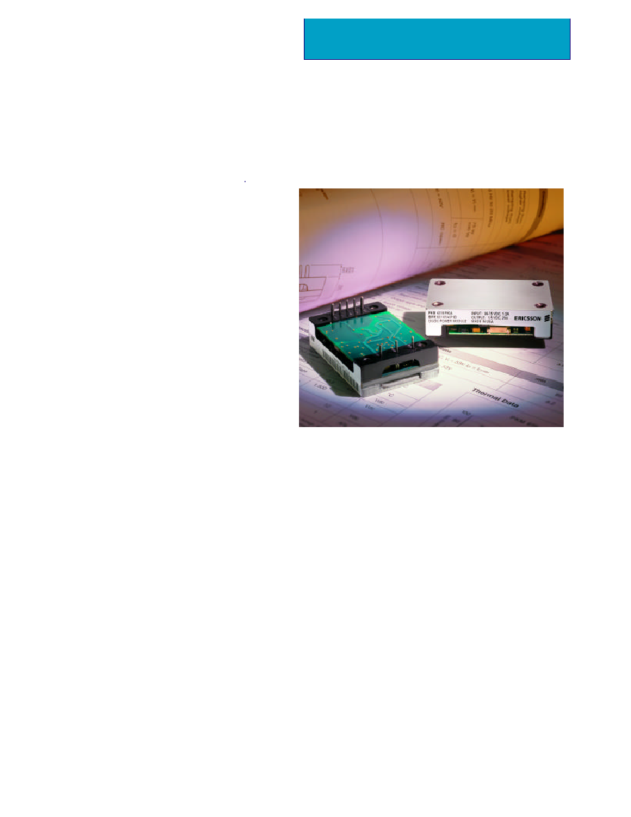
The PKM 4000 series of DC/DC power modules
represents another Ericsson "industry first" achieve-
ment in the continued development of our "third
generation" of high density, high efficiency DC/DC
power modules in an industry standard quarter
brick package with unparalleled performance. The
PKM 4113 PI module is a new addition to the se-
ries family with 76.2W/in
3
at 90% efficiency.
These breakthrough features have been achieved by
using the most advanced patented topology, ultiliz-
ing integrated magnetics and synchronous rectifica-
tion on a low resistivity multilayer PCB.
The product features fast dynamic response times
and low output ripple, which are important param-
eters when supplying low voltage logics. The PKM
4000 series is especially suited for limited board
space and high dynamic load applications
Advanced Specification
126W DC/DC Power Module
48 V Input; 12V Output
∑ High Efficiency 90% Typ
∑ Fast Dynamic Response, 150us,
+/- 100 mVpeak Typ
∑ Heatsinks available as an option for extended
operation
∑ Low Output Ripple, 75mV
p-p
Typ
∑ High power density, 76.2 W/in
3
∑ Wide input voltage range (36-75V) according
to ETSI Specifications
∑ Industry standard footprint & pin-out
∑ 1,500 Vdc isolation voltage
∑ Max case temperature +100
o
C
∑ UL 1950/UL
C
1950 Recognized Pending
∑ Demonstrated compliance with isolation
requirements equivalent to Basic Isolation
Ericsson's PKM 4000 Power Modules address the
converging "New Telecoms" market by specifying
the input voltage range in accordance with ETSI
specifications. Included in the PKM 4000 series are
over-voltage protection, under voltage protection,
over temperature protection, soft-start, and short
circuit protection. The PKM 4000 Series also offers
the flexibility of using an optional heatsink when
needed, enabling reduced airflow, extended reliabili-
ty, and higher ambient temperature operation.
These modules are manufactured using highly auto-
mated manufacturing lines with a world-class quali-
ty commitment which is reflected in our standard
five-year warranty. Ericsson Inc., Microelectronics
has been an ISO 9001 certified supplier since 1991.
For a complete product program please reference the back
cover.
PKM 4113 PI

2
EN/LZT 108 5515 R1 © Ericsson Inc., Microelectronics, January 2002
Input T
C
< T
C max
General
Connections
V
I
Input voltage range
1)
36
75 Vdc
V
Ioff
Turn-off input voltage Ramping from higher
31 33 Vdc
voltage
V
Ion
Turn-on input voltage Ramping from lower
34 36 Vdc
voltage
C
I
Input capacitance
2.8
µ
F
I
Iac
Reflected ripple 5 Hz to 20 MHz 20
mA
p-p
VTRIM Maximum input 6
Vdc
I
O
=0, V
I
= 53 V
2.6 4.6 W
Input idling power
P
Ii
Input stand-by
power
(turned off with RC)
V
I
=53V, RC open
P
RC
0.4 0.6 W
I
I max
Maximum input V
I
= V
Imin,
V
I
= 53V
current
PKM 4113 PI
4.28 A
current
1
- IN
Negative Input
2
ON/OFF
Remote control (primary).
To turn on and turn off the output.
3
+ IN
Positive Input.
4
- OUT
Negative Output.
5
- SEN
Negative Remote Sense
6
Trim
Output Voltage Adjust
7
+ SEN
Positive Remote Sense
8
+ OUT
positive Output
Pin Designation
Function
Case
Aluminum baseplate with metal standoffs.
Weight
Maximum 55 g
Pins
Pin material: Brass
Pin plating: Tin/Lead over Nickel.
Mechanical Data
Note:
1) The input voltage range 36...75 V meets the requirements in the European
Telecom Standard prETS 300 132-2 for Normal input voltage range in 48 V and
60 V DC power systems, ≠ 40.5...≠57.0 V and ≠50.0...≠72.0 V respectively.
0.21
[5,3]
PIN
EXT.
0.50
[12,7]
OVERALL
HEIGHT
0.040 [1,02] DIA. PLATED
BRASS PINS
TYPICAL 6 PLACES
0.060 [1,57] DIA. PLATED
BRASS PINS
TYPICAL 2 PLACES
Dimensions: inches [mm]
Tolerances: .xx ± 0.02 [ ,x ± ,5]
.xxx ±0.010 [,xx ± ,25]
M3 X [0,5] MOUNTING INSERTS
TYPICAL 4 PLACES
MAX. SCREW TORQUE: 3.9 IN-LBS.[0,44 N-M]
1.03
[26,16]
2.28
[57,9] OVERALL LENGTH
1.86
[47,27]
0.600
[15,24]
0.43
[10,92]
0.21
[5,33]
1.450
[36,83]
OVERALL
WIDTH
0.21
[5,33]
2.00
[50,8]
2.00
[50,8]
0.150
[3,81]
0.300
[7,62]
0.450
[11,43]
BOTTOM VIEW
0.300
[7,62]
-IN
+IN
ON/OFF
0.140
[3,56]
0.600
[15,24]
-OUT
+OUT
TRIM
-SEN
+SEN
Characteristics Conditions
min typ max Unit

3
EN/LZT 108 5515 R1 © Ericsson Inc., Microelectronics, January 2002
PKM 4113 PI (126W)
T
C
= ≠40...+100∞C, V
I
= 36 ...75V unless otherwise specified.
Absolute Maximum Ratings
Thermal Data
150
µ
s
30
40
ms
0 10.5
A
Conditions
Output
min
typ
max
Unit
Output voltage initial
setting and accuracy
T
C
=+25∞C, V
I
= 53 V, I
O
=I
Omax
V
Oi
Output voltage
tolerance band
V
O
Load regulation
V
I
= 53V, I
O
=0
to I
Omax
,
V
t r
Load transient
recovery time
t
t r
Start-up time
t
s
From V
I
connection to V
O
= 0.9
◊
V
Onom
Output current
I
O
Max output power
P
Omax
Current limit threshold
I
lim
V
O
= 0.96 V
Onom
@ T
C
<100
o
C
Short circuit current
I
sc
f < 1kHz
Output ripple & noise
Supply voltage
rejection (ac)
SVR
Line regulation
I
O
=I
Omax
Load transient
voltage deviation
11.8
12.0
12.2
V
3 10
mV
126
W
11.5 12.5
14.0
A
14.5 16.0
A
75
100
mV
p-p
V
Oac
-53
dB
+/-100
mV
I
O
=I
Omax, f < 20 MHz
Output
I
O
=0 to I
Omax
mV
3 10
Output adjust range
9.6
13.3
V
Load step = 0.25 x I
Omax
di/dt = 1A/us
OVP
Over voltage protection
14.9
15.5
V
11.6
12.4
V
At V
O
= V
Onom
V
I
= 50 V
I
O
=I
Omax
Miscellaneous
Characteristics
Conditions
Unit
min
typ
max
f
S
Switching frequency
I
O
= 0...1.0 x I
Omax
150
kHz
Efficiency
I
O
= I
Omax
, V
I
= 53V, T
C
= +25
o
C
90
%
P
d
Power dissapation
I
O
= I
Omax
, V
I
= 53V, T
C
= +25
o
C
14
W
Characteristics
Stress in excess of Absolute Maximum Ratings may cause permanent
damage. Absolute Maximum Ratings, sometimes referred to as "no
destruction limits," are normally tested with one parameter at a time
exceeding the limits of output data or electrical characteristics. If exposed
to stress above these limits, function and performance may degrade in an
unspecified manner.
T
C
Maximum Operating Case Temperature ≠ 40 +100 ∞C
T
S
Storage temperature
≠ 40 +125 ∞C
V
I
Input voltage Continuous ≠ 0.5 + 80 Vdc
V dc
V
ISO
1,500 V dc
12 Vdc
Characteristics
min max Unit
Isolation voltage
(input to output test voltage)
I
2
t
Inrush transient
1 A
2
s
V
RC
Remote control voltage
Transient (100ms) +100 V dc
PKM 4113 PI Efficiency
0.8
0.82
0.84
0.86
0.88
0.9
0.92
0
2
4
6
8
10
Output Current (A)
Efficiency (%)
36V
53V
72V

4
EN/LZT 108 5515 R1 © Ericsson Inc., Microelectronics, January 2002
Ericsson Inc., Microelectronics
1700 International Pkwy., Suite 200
Richardson, Texas 75081
Phone: 877-ERICMIC
www.ericsson.com/microelectronics
For sales contacts, please refer to our website
or call: 877-374-2642 or fax: 972-583-8355
Advanced Specification
AE/LZT 108 5515 R1
© Ericsson Inc., Microelectronics, January 2002
The latest and most complete information can
be found on our website!
Product Program
V
O
/I
O
max
V
I
Ordering No.
P
O
max
12V/10.5A
PKM 4113 PI
126 W
48/60 V
The PKM 4113 PI DC/DC power module will be
available with the different options listed in the
Product Options Table
Please check with the factory for availability.
Information given in this Advanced Specification is
believed to be accurate and reliable. No responsibility is
assumed for the consequences of its use for any
infringement of patents or other rights of third parties that
may result from its use. No license is granted by
implication or otherwise under any patent or patent rights
of Ericsson Microelectronics. These products are sold
only according to Ericsson Microelectronics' general
conditions of sale, unless otherwise confirmed in writing.
Specifications are subject to change without notice.
Option Suffix Example
Negative remote on/off - PKM 4113 PI
logic, Industry Standard
trim (i.e. V
o
Adjust)
Positive remote on/off logic P PKM 4113 PIP
Lead length 0.145"± 0.010" LA PKM 4113 PILA
Product Options