 | –≠–ª–µ–∫—Ç—Ä–æ–Ω–Ω—ã–π –∫–æ–º–ø–æ–Ω–µ–Ω—Ç: 16235FAM | –°–∫–∞—á–∞—Ç—å:  PDF PDF  ZIP ZIP |

PACIFIC DISPLAY DEVICES
LCD Component Data Sheet
Model Number: 16235
16 Character by 2 Line
Alphanumeric LCD Assembly
With Embedded Controller
CONTENTS
1. GENERAL
INFORMATION
1.1
Product
Overview
2
1.2 Part Numbering System
2
1.3
Absolute
Maximum
Ratings
3
1.4 Circuit Block Diagram
3
1.5
Mechanical
Characteristics
3
1.6 Input Signal Function
4
1.7 LCM Contrast Control and Bias
4
1.8
LCD
Dimensions
5
2.
ELECTRICAL / OPTICAL CHARACTERISTICS
2.1 DC Electrical Characteristics
6
2.2 AC Electrical Characteristics
6
2.3
Optical
Characteristics
8
2.4 LED Backlight Characteristics
10
2.5 EL Panel Backlight Characteristics
10
3.
OPERATING PRINCIPALS AND METHODS
3.1 LCD Controller Display and Control Functions
11
3.2 Display Data RAM Address Map
13
4. RELIABILITY
14
5.
PRECAUTIONS FOR USING LCD MODULES
15
516 N. Diamond Bar Blvd ≠ Suite 103 ≠ Diamond Bar, CA ≠ 91765
Tel: 909-396-5128 ≠ Fax: 909-396-1155 ≠ Web: www.pacificdisplay.com
SPECIFICATIONS FOR LIQUID CRYSTAL DISPLAY MODULE
MODEL NO: 16235
PACIFIC DISPLAY DEVICES
07.01.2003
2
1. GENERAL INFORMATION
1.1 Product Overview
∑ 16 Character x 2 line Alphanumeric Dot Matrix LCD Module
∑ LCD Controller: Embedded S6A0069 or equivalent alpha-numeric controller
∑ Multiplexing driving: 1/16 duty, 1/4 bias
∑ Operating Mode: Super Twisted Nematic (STN) technology
∑ LCD Module Service Life: 100,000 hours minimum
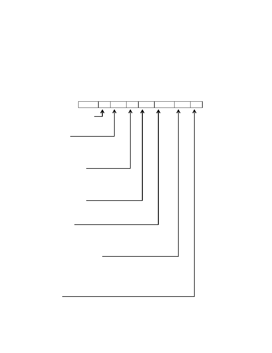
1.2 Part Numbering System
16235
-xx
-SL
-F
-ST
-LED
-GY
-12
Custom Option Designator
∑ (Can be left blank)
Operating Mode
∑ (-GR) Green
∑ (-SL) Silver
∑ (-BN) Blue Negative
Rear Polarizer Options:
∑ (-R) Reflective
∑ (-F) Transflective
∑ (-M) Transmissive
Operating Temperature
∑ (-ST) Standard (0 to +50 ∫C)
∑ (-ET) Extended (-20 to +70 ∫C)
Backlight Options:
∑ (-LED) LED Array Backlight
∑ (-ELP) EL Panel Backlight
Backlight Coloration Options:
∑ (-GY) LED - Green/Yellow
∑ (-AM) LED - Amber
∑ (-RD) LED - Red
∑ (-BG) ELP ≠ Blue Green
Viewing Angle
∑ (-6) 6 o'clock
∑ (-12) 12 0'clock
SPECIFICATIONS FOR LIQUID CRYSTAL DISPLAY MODULE
MODEL NO: 16235
PACIFIC DISPLAY DEVICES
07.01.2003
3
1.3 Absolute Maximum Ratings
Parameter Symbol
Min
Max
Unit
Supply voltage for logic
V
DD
-0.3
7.0
V
Supply voltage for LCD
V
DD
≠ V0
--
V
DD
+0.3
V
Input voltage
VI
-0.3
V
DD
+0.3
V
Standard Operating temperature
TOP (-ST)
0
50
∫C
Standard Storage temperature
TST (-ST)
-10
60
∫C
Extended Operating temperature
TOP (-ET)
-20
70
∫C
Extended Storage temperature
TST (-ET)
-30
80
∫C
Soldering Temp
Tsolder
260
∫C
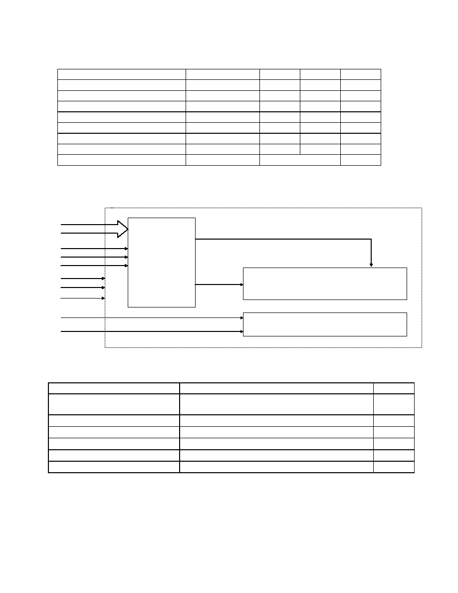
1.4 Circuit Block Diagram
1.5 Mechanical Characteristics
Item Contents
Unit
Module size (W
◊H◊T)
85 x 35 x 14.2 Max (w/ LED Backlight)
85 x 35 x 10 Max (w/ ELP or No LED Backlight)
mm
Viewing area (W
◊H)
62.2 x 17.9
mm
Character matrix (W
◊H)
5 x 8
dots
Character size (W
◊H)
2.95 x 5.55
mm
Dot size (W
◊H)
0.55 x 0.65
mm
Dot pitch (W
◊H)
0.60 x 0.70
mm
CONTROLLER
IC
S6A0069
LCD PANEL
16 CHARACTERS x 2 LINES
V
O
V
DD
VSS
E
R/W
RS
DB0
~
DB7
EL / LED BACK LIGHT
BLA
BLK
Com16
Seg80
SPECIFICATIONS FOR LIQUID CRYSTAL DISPLAY MODULE
MODEL NO: 16235
PACIFIC DISPLAY DEVICES
07.01.2003
4
1.6 Input Signal Function
Pin NO.
Symbol
Level
Description
1 VSS 0V Ground
2
VDD
5.0V
Supply voltage for logic
3
VO
---
Input voltage for LCD
4
RS
H/L
H : Data signal, L : Instruction signal
5
R/W
H/L
H : Read mode, L : Write mode
6 E
H,
H
L
Chip enable signal
7
DB0
H/L
Data bit 0
8
DB1
H/L
Data bit 1
9
DB2
H/L
Data bit 2
10
DB3
H/L
Data bit 3
11
DB4
H/L
Data bit 4
12
DB5
H/L
Data bit 5
13
DB6
H/L
Data bit 6
14
DB7
H/L
Data bit 7
15 BLA 4.2V Back
light
anode
16 BLK 0V Back
light
cathode
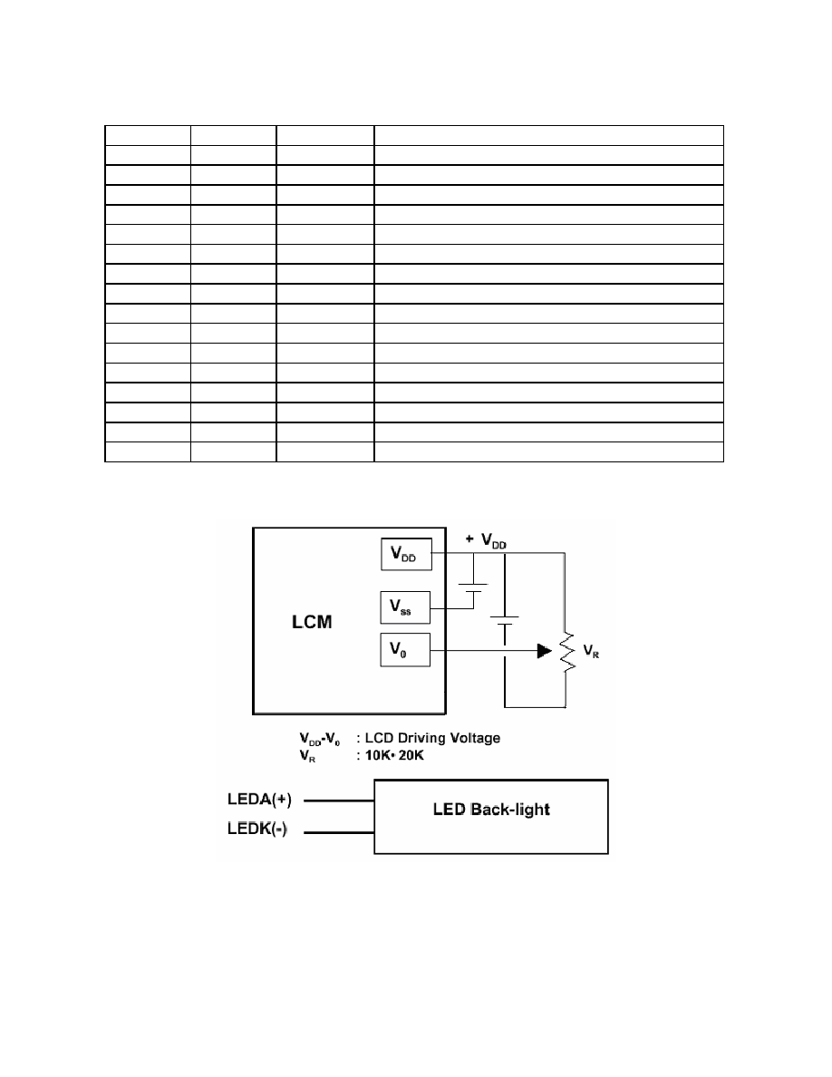
1.7 LCM Contrast Control and Bias

SPECIFICATIONS FOR LIQUID CRYSTAL DISPLAY MODULE
MODEL NO: 16235
PACIFIC DISPLAY DEVICES
07.01.2003
5
1.7 LCM Dimensions
SPECIFICATIONS FOR LIQUID CRYSTAL DISPLAY MODULE
MODEL NO: 16235
PACIFIC DISPLAY DEVICES
07.01.2003
6
2. ELECTRICAL / OPTICAL CHARACTERISTICS
2.1 DC Electrical Characteristics (V
DD
= +5V
±10% , V
SS
= 0V, Ta = 25∞C )
Parameter Symbol
Condition
Min Typ Max
Unit
Supply voltage for logic
V
DD
--- 4.5 5.0 5.5
V
Supply current for logic
I
DD
--- --- 1.38 3
mA
0∞C 4.7 5.0 5.3
V
25∞C 4.4 4.7 5.0
V
Operating voltage for LCD*
V
DD
-V
O
50∞C 4.2 4.5 4.8
V
Input voltage ' H ' level
V
IH
--- 2.2 --- VDD
V
Input voltage ' L ' level
V
IL
--- -0.3 --- 0.6
V
*Note: -ET temp range will require up to 8V biasing and require a minimum external voltage supply of -3V @-20∞C.
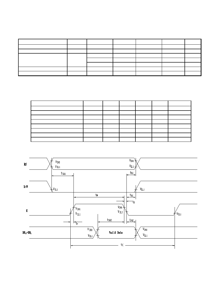
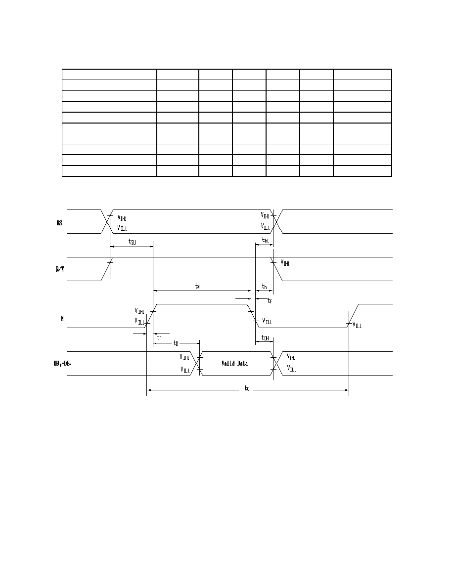
2.2 AC Electrical Characteristics
∑ Write Mode
Characteristic Symbol
Min. Typ. Max. Unit Test
pin
E cycle time
t
C
500
--- --- ns E
E rise time
t
r
---
---
25
ns E
E fall time
t
f
---
---
25
ns E
E pulse width (High, Low)
t
W
220 --- --- ns E
R/W and RS set-up time
t
SU1
40 --- --- ns
R/W,
RS
R/W and RS hold time
t
h1
10 --- --- ns
R/W,
RS
Data set-up time
t
SU2
60 --- --- ns
DB
0
~ DB
7
Data hold time
t
h2
10 --- --- ns
DB
0
~ DB
7
SPECIFICATIONS FOR LIQUID CRYSTAL DISPLAY MODULE
MODEL NO: 16235
PACIFIC DISPLAY DEVICES
07.01.2003
7
∑ Read Mode
Characteristic Symbol
Min. Typ. Max. Unit Test
pin
E cycle time
t
C
500
--- --- ns
E
E rise time
t
r
---
---
25 ns
E
E fall time
t
f
---
---
25
ns E
E pulse width
t
W
220 --- --- ns
E
R/W and RS set-up
time
t
SU
40 --- --- ns R/W,
RS
R/W and RS hold time
t
h
10
---
---
ns R/W,
RS
Data output delay time
t
D
---
---
120 ns DB
0
~ DB
7
Data hold time
t
DH
20 --- --- ns
DB
0
~ DB
7
SPECIFICATIONS FOR LIQUID CRYSTAL DISPLAY MODULE
MODEL NO: 16235
PACIFIC DISPLAY DEVICES
07.01.2003
8
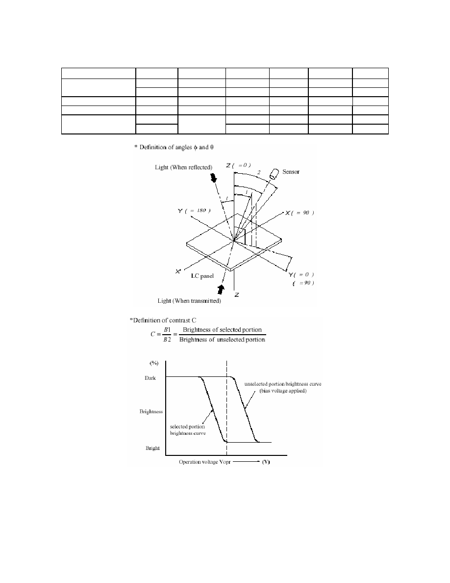
2.3 Optical Characteristics
(V
OP
= 4.7V, Ta = 25∞C )
Item Symbol
Condition
Min
Typ
Max
Unit
Response time
Tr
---
---
250
380
ms
Tf
---
---
200
300
ms
Frame Frequency
fFRM
---
---
64
---
Hz
Contrast
ratio
Cr --- 3 4 7 ---
1
-40 -- 40 Deg
Viewing angle range
2
25
∞ C
-40 -- -40
Deg

SPECIFICATIONS FOR LIQUID CRYSTAL DISPLAY MODULE
MODEL NO: 16235
PACIFIC DISPLAY DEVICES
07.01.2003
9
SPECIFICATIONS FOR LIQUID CRYSTAL DISPLAY MODULE
MODEL NO: 16235
PACIFIC DISPLAY DEVICES
07.01.2003
10
2.4 LED Backlight Characteristics
Yellow-Green LED Operating Characteristics (5V - Array Lit)
Standard
Item Symbol
Conditions
Min. Typ. Max.
Unit
Forward Voltage
V
f
Ta=
25
∞C ---
4.2
4.6 VDC
Forward Current
I
F
Ta=
25
∞C ---
120 220
mA
Reverse Voltage
V
R
Ta=
25
∞C ---
8
---
V
Life (Array or Edge Lit)
Standard
Item Conditions
Min. Max.
Unit
Life Ta=
25
∞C
100,000
---
hrs
2.5 EL Panel Backlight Characteristics
Blue-Green EL Panel Operating Characteristics:
Standard
Item Conditions
Min. Typ. Max.
Unit
Current Consumption
100VAC RMS, 400Hz
Ta: 25∞C
--- 1.8 3.1 mA
EL Drive Voltage
---
---
100
150
VAC RMS
EL Drive Frequency
---
---
400
1000
Hz
Operating Temperature
---
-35∞C
---
+50∞C
∞C
Storage Temperature
---
-40∞C
---
+60∞C
∞C
Luminance 40
50
---
cd/m
2
Luminance Half-Life
100VAC RMS, 400Hz
Ta: 25∞C
3500 --- --- Hrs
*Note: half life is defined as Luminance being reduced by 50%

SPECIFICATIONS FOR LIQUID CRYSTAL DISPLAY MODULE
MODEL NO: 16235
PACIFIC DISPLAY DEVICES
07.01.2003
11
3. OPERATING PRINCIPALS AND METHODES
∑ Control and Display Command
Command
RS
R/W
DB
7
DB
6
DB
5
DB
4
DB
3
DB
2
DB
1
DB
0
Exe Time
f=250khz
Remark
Display
Clear
L L L L L L L L L H 1.64ms
Return
Home
L L L L L L L L H X 1.64ms Cursor
move
to
first
digit
Entry
Mode
Set
L L L L L L L H I/D
SH 42
µs
∑ I/D : Set cursor move direction
∑ SH : Specifies shift of display
Display
On/Off
L L L L L L H D C B 42
µs
∑ Display
∑ Cursor
∑ Blinking
Shift
L L L L L H S/C
R/L X X 42
µs
Set
Function
L L L L H DL N F X X 42
µs
Set Cg Ram Address
L
L
L
H
CG RAM address
(corresponds to cursor address)
42
µs
CG RAM Data is sent and
received after this setting
Set Dd Ram
Address
L
L
H
DD RAM address
42
µs
DD RAM Data is sent and
received after this setting
Read Busy Flag &
Address
L
H
BF
Address Counter used for
both DD & CG RAM address
0
µs
- Reads BF indication internal
operating is being performed
- Reads addr counter contents
Write Data
H
L
Write Data
46
µs
Write data into DD or CG RAM
Read Data
H
H
Read Data
46
µs
Read data from DD or CG RAM
X : Don't care
H
Busy
BF
L
Ready
H 5 X 10 dots
F
L 5 X 7 dots
H 2 line display
N
L 1 line display
H 8 bits interface
DL
L 4 bits interface
H
Display
shift
S/C
L
Cursor
move
H
Right
shift
R/L
L
Left
shift
H
Blinking
on
B
L
Blinking
off
H
Cursor
on
C
L
Cursor
off
H
Display
on
D
L
Display
off
H
Increase
I/D
L
Decrease
H Display is shifted
SH
L Display is not
shifted
SPECIFICATIONS FOR LIQUID CRYSTAL DISPLAY MODULE
MODEL NO: 16235
PACIFIC DISPLAY DEVICES
07.01.2003
12
∑ Initializing by Instruction
Power On
|
Wait for more than 15ms after VDD rises to 4.5V
|
RS R/W DB7 DB6 DB5 DB4 DB3 DB2 DB1 DB0
0 0 0 0 1 1 * * * *
BF cannot be checked before this instruction.
Function Set
|
Wait for more than 4.1ms
|
RS R/W DB7 DB6 DB5 DB4 DB3 DB2 DB1 DB0
0 0 0 0 1 1 * * * *
BF cannot be checked before this instruction.
Function Set
|
Wait for more than 100
µs
|
RS R/W DB7 DB6 DB5 DB4 DB3 DB2 DB1 DB0
0 0 0 0 1 1 * * * *
BF cannot be checked before this instruction.
Function Set
|
|
|
|
|
BF can be checked after following
instruction.
When BF is not checked, the waiting time
between instructions is longer than execution
instruction time.
|
RS R/W DB7 DB6 DB5 DB4 DB3 DB2 DB1 DB0
0 0 0 0 1 1 N F * *
Function Set (Specify the number of display
lines and character font.) The number of
display lines and character font cannot be
changed afterwards.
0 0 0 0 0 0 1 0 0 0
Display Off
0 0 0 0 0 0 0 0 0 1
Display Clear
0 0 0 0 0 0 0 1 I/D S
Entry Mode Set
|
|
Initialization ends
SPECIFICATIONS FOR LIQUID CRYSTAL DISPLAY MODULE
MODEL NO: 16235
PACIFIC DISPLAY DEVICES
07.01.2003
13
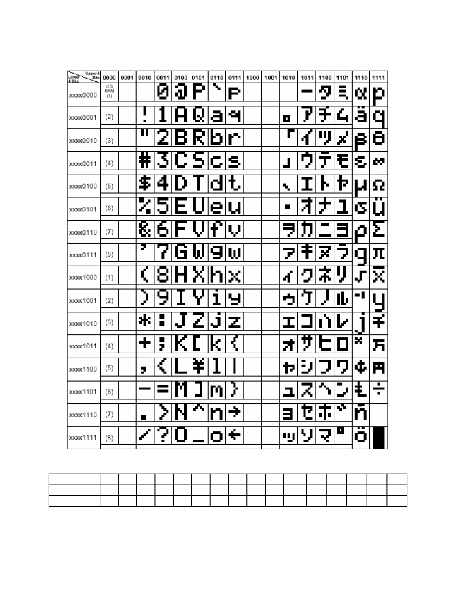
3.2 Display Data RAM Address Map
LCD Character Location map
Characters 1 2 3 4 5 6 7 8 9 10
11 12 13 14 15 16
First line
00H 01H 02H 03H 04H 05H 06H 07H 08H 09H 0AH 0BH 0CH 0DH 0EH 0FH
Second line 40H 41H 42H 43H 44H 45H 46H 47H 48H 49H 4AH 4BH 4CH 4DH 4EH 4FH
SPECIFICATIONS FOR LIQUID CRYSTAL DISPLAY MODULE
MODEL NO: 16235
PACIFIC DISPLAY DEVICES
07.01.2003
14
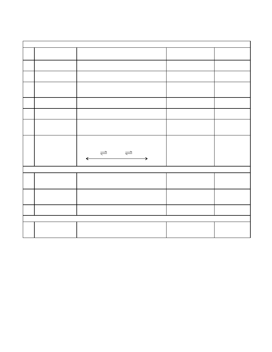
4. RELIABILITY
Environmental Test
No
.
Test Item
Content of Test Test
Condition
Applicable
Standard
1 High
temperature
storage
Endurance test applying the high storage
temperature for a long time.
80
∞C
200 hrs
------
2 Low
temperature
storage
Endurance test applying the low storage
temperature for a long time.
-30
∞C
200 hrs
------
3 High
temperature
operation
Endurance test applying the electric stress
(Voltage & Current) and the thermal stress to
the element for a long time.
70
∞C
200 hrs
------
4 Low
temperature
operation
Endurance test applying the electric stress
under low temperature for a long time.
-20
∞C
200 hrs
------
5
High temperature
/
Humidity storage
Endurance test applying the high temperature
and high humidity storage for a long time.
80
∞C , 90 %RH
96 hrs
MIL-202E-103B
JIS-C5023
6
High temperature
/
Humidity operation
Endurance test applying the electric stress
(Voltage & Current) and temperature
/ humidity
stress to the element for a long time.
70
∞C , 90 %RH
96 hrs
MIL-202E-103B
JIS-C5023
7
Temperature cycle
Endurance test applying the low and high
temperature cycle.
-20
∞C / 70∞C
10 cycles
------
Mechanical Test
8
Vibration test
Endurance test applying the vibration during
transportation and using.
10
22Hz 1.5mmp-p
22
500Hz 1.5G
Total 0.5hrs
MIL-202E-201A
JIS-C5025
JIS-C7022-A-10
9
Shock test
Constructional and mechanical endurance test
applying the shock during transportation.
50G Half sign
wave 1l msedc
3 times of each direction
MIL-202E-213B
10 Atmospheric
pressure test
Endurance test applying the atmospheric
pressure during transportation by air.
115 mbar
40 hrs
MIL-202E-105C
Others
11
Static electricity test
Endurance test applying the electric stress to the
terminal.
VS=800V , RS=1.5 k
CS=100 pF
1 time
MIL-883B-
3015.1
Supply voltage for logic system = VDD. Supply voltage for LCD system = Operating voltage at 25∞C
LCD Panel Service Life
Definition of panel service life
∑ 100,000 hours minimum at 25∞ C ±10%
∑ Contrast becomes 30% of initial value
∑ Current consumption becomes three times higher than initial value
∑ Remarkable alignment deterioration occurs in LCD cell layer
∑ Unusual operation occurs in display functions
25
∞C
5min.
1
70
∞C
30min.
-20
∞C
30min.
SPECIFICATIONS FOR LIQUID CRYSTAL DISPLAY MODULE
MODEL NO: 16235
PACIFIC DISPLAY DEVICES
07.01.2003
15
5. PRECAUTIONS FOR USING LCD MODULES
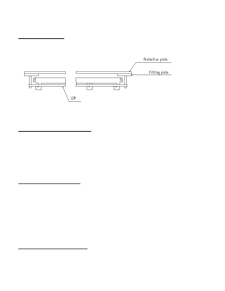
Installing LCD Modules
The hole in the printed circuit board is used to fix LCM as shown in the picture below. Attend to the following items when
installing the LCM.
1) Cover the surface with a transparent protective plate to protect the polarizer and LC cell.
2) When assembling the LCM into other equipment, the spacer to the bit between the LCM and the fitting plate
should have enough height to avoid causing stress to the module surface, refer to the individual specifications for
measurements. The measurement tolerance should be
±0.1mm.
Precaution for Handing LCD Modules
Since LCM has been assembled and adjusted with a high degree of precision, avoid applying excessive shocks to the module or
making any alterations or modifications to it.
1) Cover the surface with a transparent protective plate to protect the polarizer and LC cell.
2) Do not alter, modify or change the shape of the tab on the metal frame.
3) Do not make extra holes on the printed circuit board, modify its shape or change the positions of components to
be attached.
4) Do not damage or modify the pattern writing on the printed circuit board.
5) Absolutely do not modify the zebra rubber strip (conductive rubber) or heat seal connector.
6) Except for soldering the interface, do not make any alterations or modifications with a soldering iron.
7) Do not drop, bend or twist LCM.
Electro-Static Discharge Control
Since this module uses a CMOS LSI, the same careful attention should be paid to electrostatic discharge as for an ordinary
CMOS IC.
1) Make certain that you are grounded when handing LCM.
2) Before remove LCM from its packing case or incorporating it into a set, be sure the module and your body have
the same electric potential.
3) When soldering the terminal of LCM, make certain the AC power source for the soldering iron does not leak.
4) When using an electric screwdriver to attach LCM, the screwdriver should be of ground potentiality to minimize
as much as possible any transmission of electromagnetic waves produced sparks coming from the commutator of
the motor.
5) As far as possible make the electric potential of your work clothes and that of the work bench the ground
potential.
6) To reduce the generation of static electricity be careful that the air in the work is not too dried. A relative
humidity of 50%-60% is recommended.
Precaution for soldering to the LCM
1) Observe the following when soldering lead wire, connector cable and etc. to the LCM.
a) Soldering iron temperature : 280
∞C ± 10∞C.
b) Soldering time : 3-4 sec.
2) Solder : eutectic solder.
SPECIFICATIONS FOR LIQUID CRYSTAL DISPLAY MODULE
MODEL NO: 16235
PACIFIC DISPLAY DEVICES
07.01.2003
16
3) If soldering flux is used, be sure to remove any remaining flux after finishing to soldering operation. (This does
not apply in the case of a non-halogen type of flux.) It is recommended that you protect the LCD surface with a
cover during soldering to prevent any damage due to flux spatters.
4) When soldering the electroluminescent panel and PC board, the panel and board should not be detached more
than three times. This maximum number is determined by the temperature and time conditions mentioned above,
though there may be some variance depending on the temperature of the soldering iron.
5) When remove the electroluminescent panel from the PC board, be sure the solder has completely melted, the
soldered pad on the PC board could be damaged.
Precautions for Operation
1) Viewing angle varies with the change of liquid crystal driving voltage (VO). Adjust VO to show the best contrast.
2) Driving the LCD in the voltage above the limit shortens its life.
3) Response time is greatly delayed at temperature below the operating temperature range. However, this does not
mean the LCD will be out of the order. It will recover when it returns to the specified temperature range.
4) If the display area is pushed hard during operation, the display will become abnormal. However, it will return to
normal if it is turned off and then back on.
5) Condensation on terminals can cause an electrochemical reaction disrupting the terminal circuit. Therefore, it
must be used under the relative condition of 40
∞C , 50% RH.
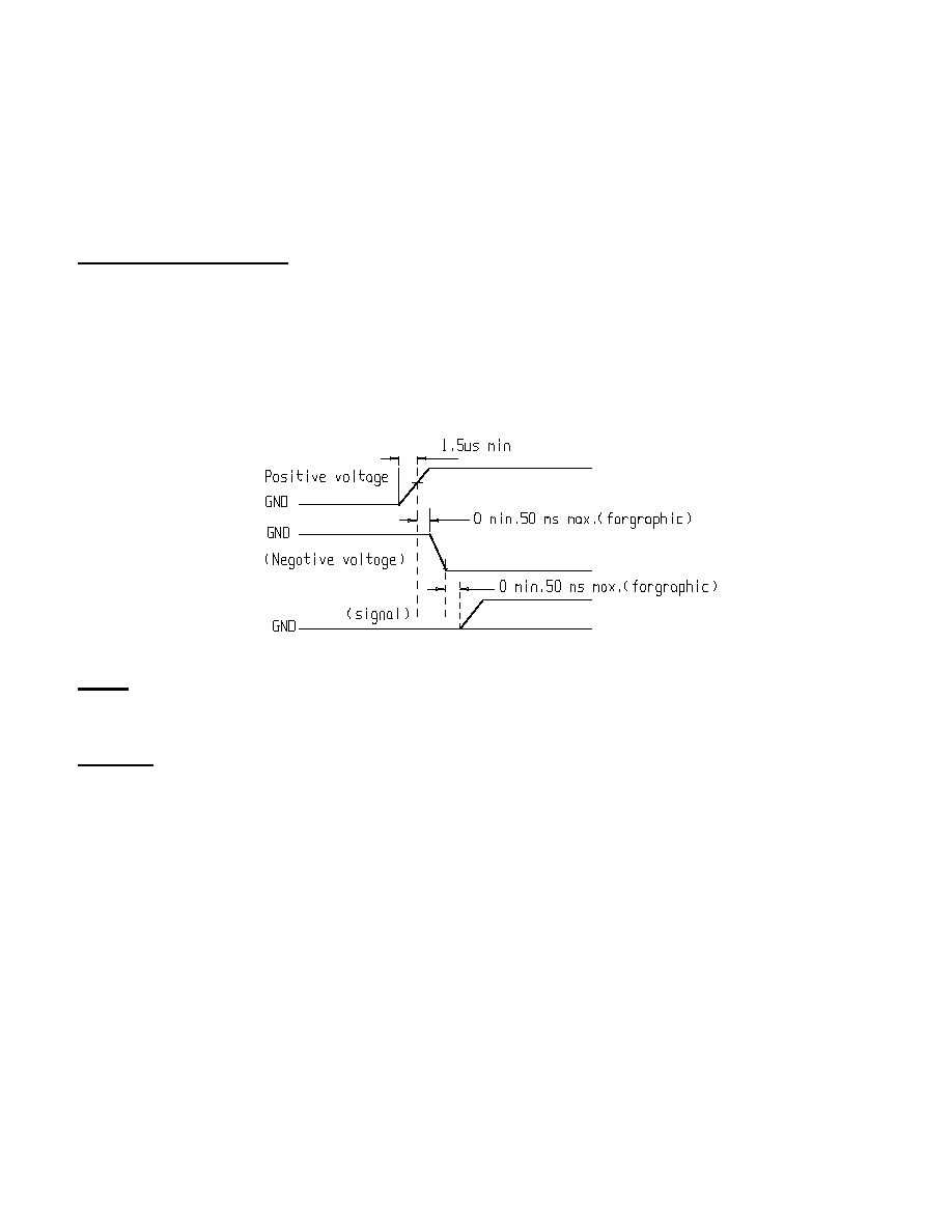
6) When turning the power on, input each signal after the positive/negative voltage becomes stable.
Safety
∑ If the LCD panel breaks, be careful not to get the liquid crystal in your mouth. If the liquid crystal touches your skin
or clothes, wash it off immediately using soap and plenty of water.
Handling
∑ The display panel is made of glass. Do not subject it to a mechanical shock by dropping it or impact.
∑ If the display panel is damaged and the liquid crystal substance leaks out, be sure not to get any in your mouth. If the
substance contacts your skin or clothes, wash it off using soap and water.
∑ Do not apply excessive force to the display surface or the adjoining areas since this may cause the color tone to vary.
∑ The polarizer covering the display surface of the LCD module is soft and easily scratched. Handle this polarizer
carefully.
∑ If the display surface becomes contaminated, breathe on the surface and gently wipe it with a soft dry cloth. If it is
heavily contaminated, moisten cloth with one of the following solvents :
o Isopropyl alcohol
o Ethyl alcohol
∑ Solvents other than those above-mentioned may damage the polarizer. Especially, do not use the following.
o Water
o Ketone
o Aromatic solvents
∑ Exercise care to minimize corrosion of the electrode. Corrosion of the electrodes is accelerated by water droplets,
moisture condensation or a current flow in a high-humidity environment.
∑ Install the LCD Module by using the mounting holes. When mounting the LCD module make sure it is free of
twisting, warping and distortion. In particular, do not forcibly pull or bend the I
/O cable or the backlight cable.
∑ Do not attempt to disassemble or process the LCD module.
∑ NC terminal should be open. Do not connect anything.
∑ If the logic circuit power is off, do not apply the input signals.

SPECIFICATIONS FOR LIQUID CRYSTAL DISPLAY MODULE
MODEL NO: 16235
PACIFIC DISPLAY DEVICES
07.01.2003
17
∑ To prevent destruction of the elements by static electricity, be careful to maintain an optimum work environment.
o Be sure to ground the body when handling the LCD modules.
o Tools required for assembling, such as soldering irons, must be properly grounded.
o To reduce the amount of static electricity generated, do not conduct assembling and other work under dry
conditions.
o The LCD module is coated with a film to protect the display surface. Exercise care when peeling off this
protective film since static electricity may be generated.
Storage
∑ When storing the LCD modules, avoid exposure to direct sunlight or to the light of fluorescent lamps
∑ Store the module in a dark place where the temperature is 25
o
C ±10
o
C and the humidity below 65% RH.
∑ Do not store the module near organic solvents or corrosive gases.
∑ Do not crush, shake, or jolt the module (including accessories).
Cleaning
∑ Do not wipe the polarizing plate with a dry cloth, as it may scratch the surface.
∑ Wipe the module gently with soft cloth soaked with a petroleum benzene.
∑ Do not use ketonic solvents (ketone and acetone) or aromatic solvents (toluene and xylene), as they may damage the
polarizing plate.
Others:
∑ Liquid crystals solidify under low temperature (below the storage temperature range) leading to defective orientation
or the generation of air bubbles (black or white). Air bubbles may also be generated if the module is subject to a low
temperature.
∑ If the LCD modules have been operating for a long time showing the same display patterns, the display patterns may
remain on the screen as ghost images and a slight contrast irregularity may also appear. A normal operating status can
be regained by suspending use for some time. It should be noted that this phenomenon does not adversely affect
performance reliability.
∑ To minimize the performance degradation of the LCD modules resulting from destruction caused by static electricity
etc., exercise care to avoid holding the following sections when handling the modules.
-
Exposed area of the printed circuit board.
-
Terminal electrode sections.