USR Semiconductor Co., Ltd
DIODE
MODULE
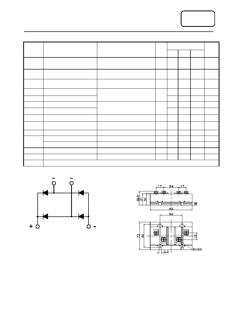
2D150
OUTLINE DRAWING & CIRCUIT DIAGRAM
VALUE
SYMBOL
CHARACTERISTIC
TEST CONDITIONS
T
j
(
∞
C)
Min Type Max
UNIT
I
O
DC output current
Single-phase full wave rectifying
circuit, T
C
=100∞C
150
150
A
V
RRM
Repetitive peak reverse voltage
V
RRM
tp=10ms
V
RsM
= V
DRM
&V
RRM
+200V
150
600
1800
V
I
RRM
Repetitive peak current
at V
RRM
150
10
mA
I
FSM
Surge forward current
2.50
KA
I
2
t
I
2
T for fusing coordination
10ms half sine wave
V
R
=0.6V
RRM
150
31.8 A
2
s*10
3
V
FO
Threshold voltage
0.80
V
r
F
Forward slop resistance
150
3.8
m
V
FM
Peak forward voltage
I
FM
=225A
25
1. 655
V
R
th(j-c)
Thermal resistance
Junction to heatsink
Single side cooled
0.150
∞
C /W
V
iso
Isolation voltage
50Hz,R.M.S,t=1min,I
iso
:1mA(max)
2500
V
Terminal connection torque(M4)
1.5
N∑m
F
m
Mounting torque(M6)
3.0
N∑m
T
stg
Stored temperature
-40
125
∞
C
W
t
Weight
430
g
Outline
410F4
USR Semiconductor Co., Ltd
DIODE
MODULE
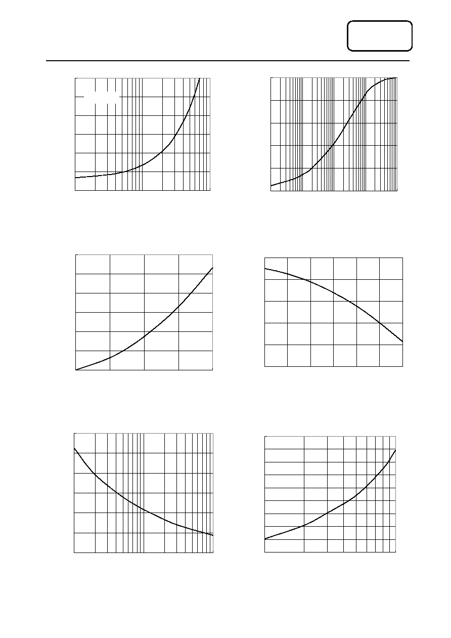
Fig.1
Fig.2
Fig.5
Fig.6
Fig.4
Fig.3
MDQ/S150
0.5
1
1.5
2
2.5
3
3.5
10
100
1000
Instantaneous on-state currant,amperes
I
n
s
t
a
n
t
a
n
e
o
u
s
o
n
-
s
t
a
t
e
v
o
l
t
a
g
e
,
v
o
l
t
s
Peak forward Voltage Vs.Peak forward Current
Tj=150∞C
0.15
0
0.03
0.06
0.09
0.12
0.15
0.001
0.01
0.1
1
10
time
S
T
r
a
n
s
i
e
n
t
t
h
e
r
m
a
l
i
m
p
e
d
a
n
c
e
,
∞
C
/
W
Max. junction To case Thermai Impedance Vs.Time
2.50
0.4
0.8
1.2
1.6
2
2.4
2.8
1
10
100
Cycles at 50Hz
T
o
t
a
l
p
e
a
k
h
a
l
f
-
s
i
n
e
s
u
r
g
e
c
u
r
r
e
n
t
,
k
A
Surge Current Vs.Cycles
31.8
8
11
14
17
20
23
26
29
32
35
1
10
Time,m.seconds
M
a
x
i
m
u
m
I
2
t
(
K
a
m
p
s
2
,
s
e
c
s
)
I
2
t Vs.Time
MDQ150
0
100
200
300
400
500
600
0
50
100
150
200
Mean on-state current,amperes
M
a
x
.
o
n
-
s
t
a
t
e
d
i
s
s
i
p
a
t
i
o
n
,
w
a
t
e
s
Max. Power Dissipation Vs.Mean forward Current
MDQ150
60
80
100
120
140
160
0
30
60
90
120
150
180
Mean on-state current,amperes
C
a
s
e
t
e
m
p
e
r
a
t
u
r
e
,
∞
C
Max. case Temperature Vs.Mean forward Current