 | –≠–ª–µ–∫—Ç—Ä–æ–Ω–Ω—ã–π –∫–æ–º–ø–æ–Ω–µ–Ω—Ç: 3P3210000 | –°–∫–∞—á–∞—Ç—å:  PDF PDF  ZIP ZIP |
M-16
Dimensions are shown: IN (mm)
Dimensions subject to change
www.ittcannon.com
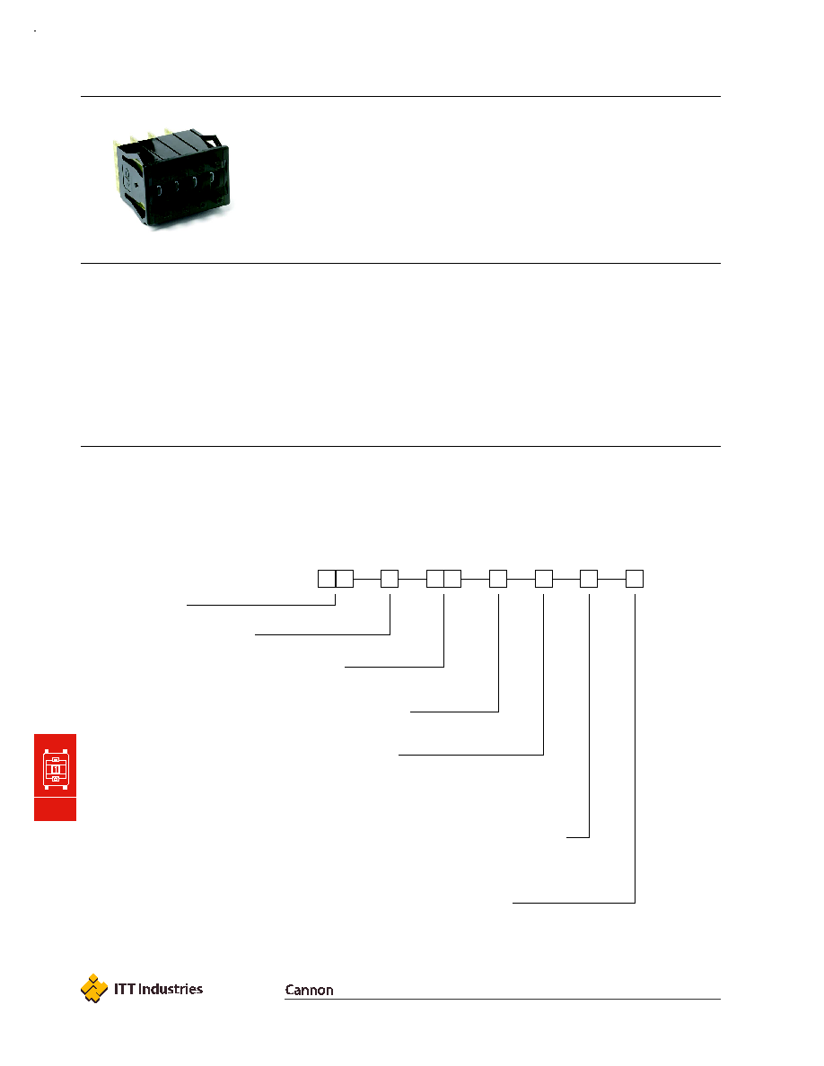
C&K 3P Series
Miniature Pushwheel Switches
M
Thumbwheel & Pushwheel
Features/Benefits
∑
Snap-in front mount design for
easy assembly
∑
10 position models available
Illuminated backlighting available
Typical Applications
∑
Test & measurement equipment
∑
Industrial machinery
∑
Computer peripherals
Specifications
CONTACT RATING:
CARRY: 1 AMP continuous.
SWITCH: 0.4 VA max., 100 mA max., 28 V DC max.
OPERATING VOLTAGE: 50 mV to 28 V DC.
ELECTRICAL LIFE: 100,000 actuations.
CONTACT RESISTANCE: Below 300 m
typ. @
2-4 V DC, 100 mA.
INSULATION RESISTANCE: 109
min. (dry).
DIELECTRIC STRENGTH: 500 Vrms min. @ sea level
between common terminal and any output.
OPERATING TEMPERATURE: ≠10∫C to 65∫C.
Materials
HOUSING: Polycarbonate (UL 94V-0).
PUSHWHEEL: Polycarbonate (UL 94V-0).
PUSHBUTTON: Polycarbonate (UL 94V-0).
ROTOR CONTACTS: Gold over nickel over copper alloy.
STATOR CONTACTS: Hard gold over nickel over copper
on epoxy fiberglass.
NOTE: Specifications and materials listed above are for switches with standard options.
For information on specific and custom switches, consult Customer Service Center.
Build-A-Switch
To order, simply select desired option from each category and place in the appropriate box. Available options are shown and
described on pages M-17 thru M-19. For additional options not shown in catalog, consult Customer Service Center.
Consult factory for illumination availability.
Series
3P
(STD.) Miniature pushwheel
Number of Sections
0
Switch section
1
1 Switch section
2
2 Switch sections
3
3 Switch sections
4
4 Switch sections
Dust Lens
0
(STD.) No Iens
2
Dust lens
Function Code
21
BCD 1-2-4-8
23
Complement of BCD 1-2-4-8
Terminations
0
(STD.) Short PCB
1
Extended PCB
3
Short PCB with solder pins
9
Any combination
A
Extended PCB with solder pins
Color/Marking/Stops
0
Matte black housing, gloss black wheel,
white marking, black pushbutton
9
Combination of body colors, wheel colors,
marking and/or stops
Mounting Style
0
Snap-in, front mount
3
Snap-in, front mount
M-17
Dimensions are shown: IN (mm)
Dimensions subject to change
www.ittcannon.com
C&K 3P Series
Miniature Pushwheel Switches
SERIES
NUMBER OF SECTIONS
FUNCTION CODE
Third Angle
Projection
M
Thumbwheel & Pushwheel
Available Terminations: 0, 1, 3
See figs. 2 & 3, page M-19.
Available Terminations: A, 0, 1, 3
See figs. 2 & 3, page M-19.
N = Number of sections.
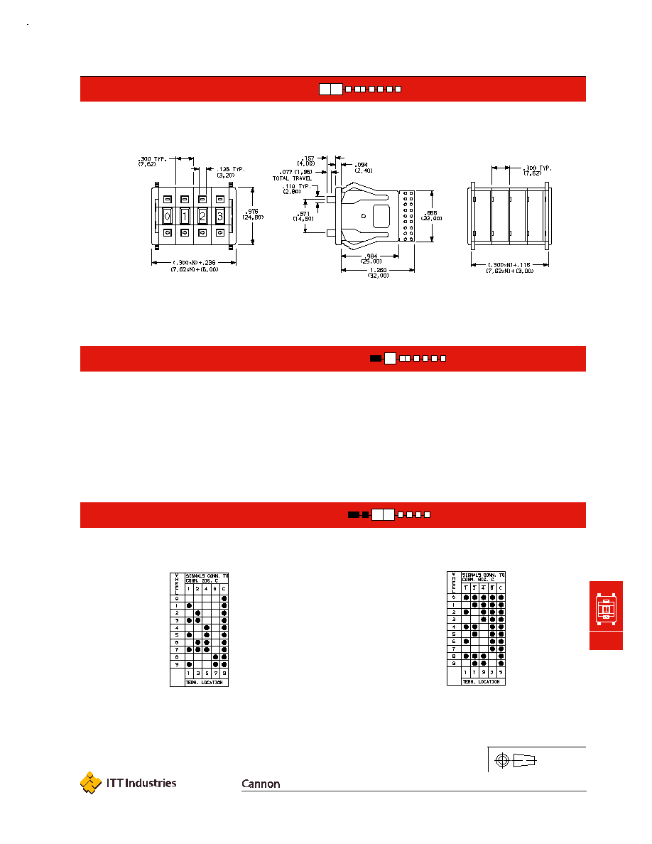
23
COMPLEMENT OF BCD 1-2-4-8,
10 POSITION
21
BCD 1-2-4-8, 10 POSITION
3P
(STD.) MINIATURE PUSHWHEEL SWITCH
1-4
Number of switch sections in assembly, includes endplates.
0
Switch section only, no endplates.
NOTE: For terminal location diagrams, see page M-19.
NOTE: Endplates and blank sections available separately, see page M-20.
M-18
Dimensions are shown: IN (mm)
Dimensions subject to change
www.ittcannon.com
C&K 3P Series
Miniature Pushwheel Switches
MOUNTING STYLE
TERMINATIONS
M
Thumbwheel & Pushwheel
N = Number of sections.
N = Number of sections.
Signal traces cut, except for common(s).
For terminal location numbers, see next page.
9
ANY COMBINATION OF TERMINATION
CONFIGURATIONS OR SPECIAL TERMINATIONS
A
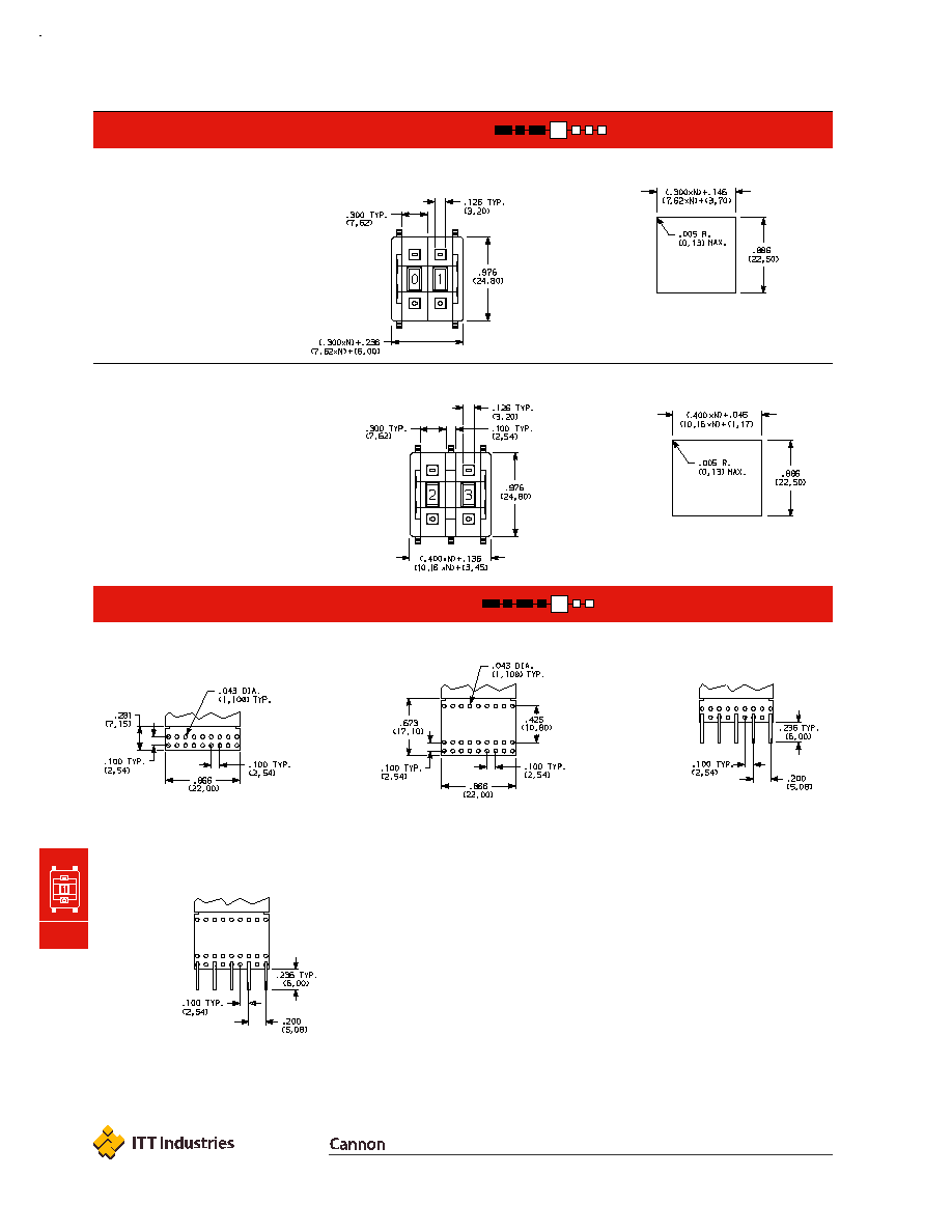
EXTENDED PCB, TYPE 1 WITH
SOLDER PINS
1
EXTENDED PCB WITH PROVISION
FOR COMPONENTS
3
SHORT PCB, TYPE 0 WITH SOLDER PINS
0
(STD.) SHORT PCB
3
SNAP-IN FRONT MOUNT WITH SPACER,
SECTION PITCH: .400 (70,16) EACH SECTION, LAST SECTION .300 (7,62)
0
SNAP-IN FRONT MOUNT,
SECTION PITCH: .300 (7,62) EACH SECTION
Recommended panel thickness:
.039-.156
(0,99-3,95)
Recommended panel thickness:
.039-.156
(0,99-3,95)
Specify on configuration form, page M-21
and consult Customer Service Center.
PC Board 1/32" (0,79) thick.
For terminal location numbers, see next page.
Signal traces cut, except for common(s).
NOTE: All terminal holes shown may not be present for all function codes,
consult Customer Service Center.

M-19
Dimensions are shown: IN (mm)
Dimensions subject to change
www.ittcannon.com
C&K 3P Series
Miniature Pushwheel Switches
TERMINATIONS
COLOR/MARKING/STOPS
DUST LENS
Third Angle
Projection
M
Thumbwheel & Pushwheel
Fig. 1
Solder Pins
Fig. 2
2
DUST LENS (Protects character face of the wheel from abrasion and dust.)
0
(STD.) NO LENS
9
SPECIAL COLORS, MARKINGS FOR HOUSING OR WHEEL, STOPS (Specify on CONFIGURATION FORM, page M-21 and consult Customer Service Center).
0
(STD.) MATTE BLACK HOUSING (Gloss black wheel with white characters, black pushbuttons, no stops.)
Terminal Location Numbers
M-20
Dimensions are shown: IN (mm)
Dimensions subject to change
www.ittcannon.com
C&K 3P Series
Miniature Pushwheel Switches
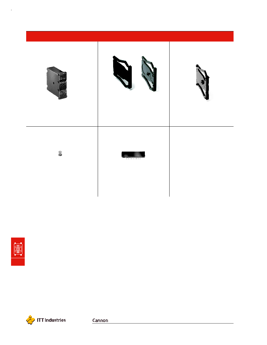
AVAILABLE HARDWARE
M
Thumbwheel & Pushwheel
Blank sections, .300 THK.
PART NO.
663702000
BLACK
663709000
GRAY
Stop pins
PART NO.
657800000
Terminal connnector
PART NO.
630000000
Spacers, .100 THK.
(Makes section pitch .400)
PART NO.
663602000
BLACK
663609000
GRAY
End plates
One left and one right
piece required for
complee assembly.
Fits 0, 1
terminations only.
PART NO.
623502000
LEFT-BLACK
623509000
LEFT-GRAY
623602000
RIGHT-BLACK
623609000
RIGHT-GRAY
LEFT-with hole
RIGHT-with pin
M-21
Dimensions are shown: IN (mm)
Dimensions subject to change
www.ittcannon.com
C&K 3P Series
Miniature Pushwheel Switches
M
Thumbwheel & Pushwheel
QUALITY CONTROL INSTRUCTIONS
PRODUCTION APPROVAL
DATE
C&K PART NUMBER
REV.
INITIALS
DATE
3
CATALOG PART NO.
COMPANY NAME
CUSTOMER
PRINT
REVISION:
ADDRESS
TEL.#
CUSTOMER CONTACT
DATE
ORIGINATED BY
SALES REP.
DETAILS:
Q.C. APPROVAL
DATE
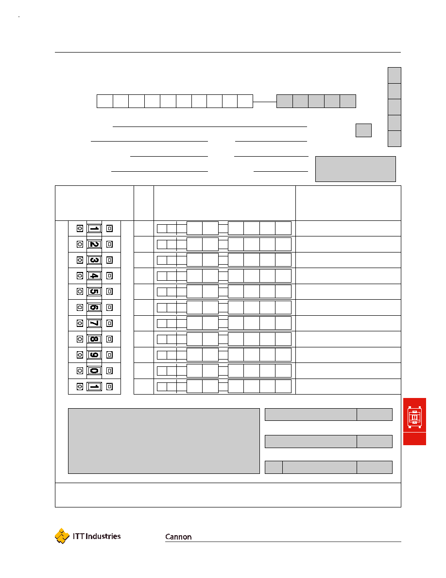
Configuration Form
GRAY SHADED AREAS TO BE FILLED IN BY CUSTOMER SERVICE.
SHEET _____ OF _____
C&K P
A
R
T
NUMBER
10
11
1
2
3
4
5
6
7
8
9
PUSHWHEEL
SECTIONS
DESCRIBE IN APPROPRIATE ROW
SPECIAL INSTRUCTIONS OR SPECIFICATIONS:
3 P
FUNCTION CODE ≠ TERMINATIONS ≠
COLOR/MARKING/STOPS/SEAL ≠
ILLUMINATION
FOR SWITCHES WITH MORE THAN 11 SECTIONS, CONTINUE ON ADDITIONAL SHEETS.
ENTER OPTION CODES IN APPROPRIATE BOXES. FUNCTION
CODES INCLUDE BLANK SECTIONS (SEE PAGE M-17).
NO.
OF
SEC.
≠
3 P
≠
3 P
≠
3 P
≠
3 P
≠
3 P
≠
3 P
≠
3 P
≠
3 P
≠
3 P
≠
3 P
≠
P
≠
≠
≠
≠
≠
≠
≠
≠
≠
≠
≠