 | –≠–ª–µ–∫—Ç—Ä–æ–Ω–Ω—ã–π –∫–æ–º–ø–æ–Ω–µ–Ω—Ç: 40-1.10EN | –°–∫–∞—á–∞—Ç—å:  PDF PDF  ZIP ZIP |

s
Multipoint potentiometric recorder for 6 measuring points
s
1 to 6 measuring ranges for standard signals and direct
sensor connection
s
Last dot visible form front
s
Roll or fanfold chart
s
Format 144 mm x 144 mm
s
Installed depth 305 mm
s
Instrinsic safety for signal circuit protection
s
Mounting within or outside the hazardous
area
Multipoint Recorder Arucomp EK-Ex. A
01.97
Data Sheet
40-1.10 EN
Measuring section
Error limit
Accuracy class 0.5 according to DIN 43782/IEC 484 for
basic unit 0...5 mV Meþabweichung
Measuring ranges
Via range box type Arucomp 4900/EK-Ex at rear of unit
Incremental error
without zero shift
0.2 % of span
with zero shift
0.3 / of span
zero shift
1 mA
including temperature effect
0.2 % / 10 K
R
e
= 20 k
/V at leat 20 k
Thermometer current I
th
1 mA
Lead balancing for mV in range 0...40
unnecessary
For
in 3-wire circuit necessary
For
in two-wire circuit of 10
; 0.1 % external
Reference junction
Optionally external or built into range box.
Caution!
Note temperature difference between terminals and range
box
Measuring range limit data
Current measurement
I
e max.
±
50 mA; I
e min.
±
0.1 mA
Span
min. 0.1 mA; max. 100 mA
R
e
7
I
(
mA
)
[
]
Voltage measurement
≠25 V DC...+25 V DC
Span
min. 5 mV DC; max. 25 V DC
R
e
20 k
/V; jedoch min. 20 k
Zero shift with constant current source
±
600 % of selected span (max. 6/7 of upper range value)
Resistance measurement
Scale span
min. 8
; max. 500
Circuit designation
Direct voltage and thermocouples with external reference
junction
without zero shift circuit
measuring circuit W 21
with zero elevation
W 22 K
with zero suppression
W 23 K
Resistance measurement
Resistance thermometer
in 2-wire circuit
W 24 K
in 3-wire circuit
W 25 K
Resistance teletransmitter in 3-wire circuit
W 26 K
Current measurement
without zero shift
W 28
with zero elevation
W 27 K
with zero suppression
W 28 K
Continuous overload capacity of signal inputs
±
25 V
electrical motor current switched off at ≠0.5 % and 100.5 %
Recording section
Scale
interchangeable for all measuring ranges with either 1...6
graduated scales or single scale strips with one graduated
scale each
Scale type
No. of
graduated scales
1 2 3 4
,5
5
,5
6
,5
single scale
Digit size
(mm)
6 5 3 2.5 2
,5
2
,5
3
Size of main
graduations
8 6 4 3
,5
2.5 1.8 3
Colour sequence
Violet, red, black, green, blue, brown (DIN 43 838)
Last point visible form front
ink supply for 5
◊
10
5
dots per colour
Drive
Common synchronous motor for chart drive, measuring
point selector switch and print head
Dotting rate
5/10/20 s selectable
Chart drive
10/20/60/120 mm/h selectable
Recording width
100 mm (chart width 120 mm) to DIN 16 230
Chart length
Roll chart 32 m (approx 66 days at 20 mm/h)
Fanfold chart 16 m (approx 33 days at 20 mm/h)
Chart feed-in
Automatic (roll chart)
Power supply
24 V or 115 V or 230 V; 50 Hz or 60 Hz
Tolerated temperature deviation +10 %, ≠15 %
Typical power consumption approx. 8 VA
General and safety data
Environmental capabilities
Ambient temperature
0...25...50
∞
C
Transport and storage temperature
≠25...+70
∞
C
Climatic category
KWE to DIN 40 040
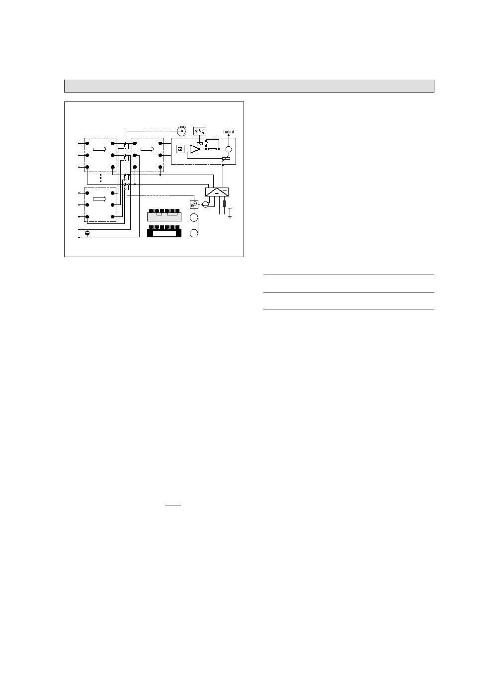
Technical data
Functional diagram
K
C
M
M
D
K+
-
+
-
+
-
62
61
63
Pos.6
K
K
C
M
M
D
+
-
+
-
+
-
12
11
13
Pos.1
K
K
C
M
M
D
+
-
+
-
+
-
Pos.7
901
801
S2
S1
S4
S3
0...5mV
M
MS
I
K
1
2
N L1 PE
10, 20,
60, 120 mm/h
K+
K
-
C+
M
-
M+
D
-
K+
K
-
C+
M
-
M+
D
-
a
b
Z-14901
Multipoint Recorder Arucomp EK-Ex. A
Data Sheet
40-1.10 EN
Page 2 of 6
01.97

Relative humidity
75 % annual average; avoid condensation; max. relative
humidity
80 % in operation; pay attention to influence of
humidity on chart paper to DIN 16234
Electrical safety tested to DIN VDE 0411 Part 1 / IEC 348
Class of protection I
Measuring circuits; functional extra-low voltage with safe
isolation to VDE 0110 Part 410
Test voltage
1.5 kV power supply to case
4
,4
kV measuring circuit to power supply
0.5 kV measuring circuits to case
0.5 kV measuring circuits to measuring circuits
Overvoltage category III
Degree of contamination 3
to DIN VDE 0110 Part 101
Electromagnetic compatibility
The safety requirements stated in the EMC directive 89/336/
EWG, May 1989 shall be fulfilled with respect to immunity to
electromagnetic interference to drafted EN 50082.2
Radio interference suppression
Suppression class N to VDE 0875 or EN 55014
Connection, case and mounting
Electrical connections
Type of protection IP 20
Tab connector A 6.3
◊
0.8 or A 2.8
◊
0.8 or
MTP 2.4
◊
0.8 or as accessory
Screw terminal for 2
◊
1.5 mm
2
wire
Power supply
Type of protection IP 54
Screw terminals for 1.5 mm
2
wire
Case
Sheet metal for panel or mosaic panel field mounting
Colour RAL 7032, Protection IP 54,
Door made of polycarbonate
Operating orientation
vertical
±
45 ∞
Monting distance
horizontal or vertical 0 mm,
case door must be open also at 100
∞
Weight
approx. 5.5 kg
Labelling facilities
On the measuring point designation plate in the door,
31 characters per measuring point
Parts supplied with the first unit
1 Operating manual
2 Fastening elements to DIN 43834
2 Roll or fanfold charts
1 Ink holder (print star)
Explosion protection
Manufacturer's code
49/40-23 Ex
Certificate of conformity
PTB No. Ex-92.C.2082
Type of protection
EEx m (ib) e d IIB T4
Mounting
within the hazardous zone 1
Measuring circuits
(Terminals 11, 12, 13; 21, 22, 23; 31, 32, 33; 41,
42, 43; 51, 52, 53; 61, 62, 63; 801, 901)
in type of protection intrinsically safe EEx ib IIB or EEx ib IIC
1. Measuring circuits for current, voltage and resistance
with range box Arucomp 4900/EK-Ex
-Ex W21, -Ex W21KV, -Ex W22KV, -Ex W22K, -Ex W23 KV,
-Ex W23K, -Ex W24K, -Ex W24K2, -Ex W25K, -Ex W25K2,
-Ex W26K, -Ex W27K, -Ex W28, -Ex W28K
Max. values per measuring circuit:
U = 10 V
I
K
= 65 mA
P = 400 mW
The effective internal inductance is negligibly low.
The effective internal capacitanc is 12 nF.
Max. permitted values of the connected intrinsically safe
circuits:
1.1. Connection to passive intrinsically safe circuits
Group IIC
Group IIB
Max. external inductance La 5 mH
20 mH
Max. external inductance Ca. 4
µ
F
30
µ
F
1.2 Connection to certified active intrinsically safe circuits
Max values per circuit
U = 25 V
P = 600 mW
The maximum internal inductanceLa and capacitance Ca
depending on the respective max. values of the connected
intrinsically safe circuit can be taken from tables 1,2 and 3 of
the certificate of conformity.
2. Measuring circuits for current
with range box Arucomp 4900/EK-Ex
-Ex W28, -Ex W27K, -Ex W28K with input resistance R
e
7
Max. values per circuit
U = 0.5 V
I
K
= 65 mA
P = 8 mW
The effective internal inductance is negligibly low.
The effective internal capacitanc is 12 nF.
Max. permitted values of the connected intrinsically safe
circuits:
Max values per circuit
U = 20 V
I = 170 mA
The maximum internal inductance La and capacitance Ca
depending on the respective max. values of the connected
intrinsically safe circuit can be taken from tables 4 and 5 of
the certificate of conformity.
The six measuring circuits are electrically isolated. The
respective measuring circuit in operation and the circuit for
the external reference junction are electrically coupled.
Note:
The values mentioned above do not apply to a plug
connection. Those values can be taken from the annex
to the certificate of conformity.
}
Technical data
Multipoint Recorder Arucomp EK-Ex. A
Data Sheet
40-1.10 EN
01.97
Page 3 of 6

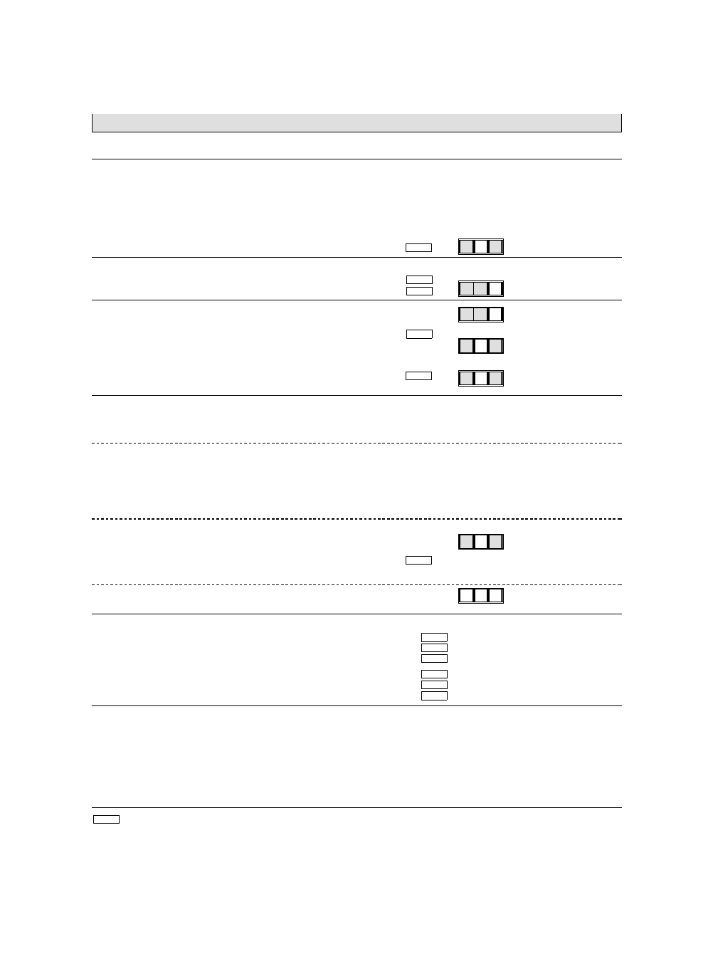
Ordering information
Consumables
Multipoint recorder Arucomp EK-Ex. A
Catalogue No.
-
-
Basic unit
1)
. . . . . . . . . . . . . . . . . . . . . . . . . . . . . . . . . . . . . . . . . . . . 05
DM 6.360,≠
Application circuit SW (one measuring range) . . . . . . . . . . . . . . . . . . . . . . . . . . 06
DM 6.520,≠
Application circuit MW (one to six measuring ranges) . . . . . . . . . . . . . . . . . . . . . . 07
DM 6.995,≠
Power supply
24 V 50 Hz . . . . . . . . . . . . . . . . . . . . . . . . . . . . . . . . . . . . . . . . . . . 1
DM
≠
115 V 50 Hz . . . . . . . . . . . . . . . . . . . . . . . . . . . . . . . . . . . . . . . . . . . 2
DM
≠
230 V 50 Hz . . . . . . . . . . . . . . . . . . . . . . . . . . . . . . . . . . . . . . . . . . . 3
DM
≠
24 V 60 Hz . . . . . . . . . . . . . . . . . . . . . . . . . . . . . . . . . . . . . . . . . . . 6
DM
≠
115 V 60 Hz . . . . . . . . . . . . . . . . . . . . . . . . . . . . . . . . . . . . . . . . . . . 7
DM
≠
230 V 60 Hz . . . . . . . . . . . . . . . . . . . . . . . . . . . . . . . . . . . . . . . . . . . 8
DM
≠
Recording
On roll chart . . . . . . . . . . . . . . . . . . . . . . . . . . . . . . . . . . . . . . . . . . . . 1
DM
80,≠
On fanfold chart . . . . . . . . . . . . . . . . . . . . . . . . . . . . . . . . . . . . . . . . . . 3
DM
≠
Catalogue No.
-
-
For ordering the Catalogue No. suffices.
If necessary suffix supplementary Nos. to the catalogue numbers.
1)
Measuring basis 0...5 mV, without range box and scales
4 1 0 1 1
0
0
0
1
0
0
1
0
0
1
4 1 0 1 1
0 0 1
0
Catalogue No.
DM
Ink holder
41081-4-0859569
51,50*
Chart paper
Roll chart (supplied in packs of 10)
with hourly time imprint for 20 mm/h
40920-0-3000505
7,55
without hour imprint, with baselines
40920-0-3000150
7,55
Fanfold chart (supplied in packs of 20)
with hourly time imprint for 20 mm/h
40926-0-3000502
7,55
without hour imprint, with baselines
40926-0-3000003
7,55
Other charts paper see Data Sheet 49-9.10 EN.
Multipoint Recorder Arucomp EK-Ex. A
Data Sheet
40-1.10 EN
Page 4 of 6
01.97
Additional ordering information
At least one specification is necess. for every measuring range and group
Suppl. No.
DM
Specification for measuring range 1
1
Specification for measuring range 2
2
Specification for measuring range 3
3
Specification for measuring range 4
4
Specification for measuring range 5
5
Specification for measuring range 6
6
The
following
specification
applies
to
measuring
point(s)
e.g.
2
and
5)
1)
Measuring circuit designation depending on the measuring tasks
Measuring circuit W2. or W2.K
5
≠
Measuring circuit W2.KV (built-in reference junction correction)
6
1)
51,≠
Measuring range
1)
Code according to Data Sheet 40-1.00 EN
1 ( ... )
≠
As specified
2
95,≠
1)
Code for external reference junction temperature
With test resistor in dismantled form for
∞
C Pt 100 IEC
1)
23,50
Scale specifications
Scale on wide scale plate
506
≠
(for large digits with 1 or 2 graduations or max. 6 graduations)
1st graduation
1
2nd graduation
2
3rd graduation
3
4th graduation
4
5th graduation (only applies in connection with Suppl. No. 506)
5
6th graduation (only applies in connection with Suppl. No. 506)
6
Without graduation, scale start and end marked (for 1st graduation only)
1
-34,50
Graduation 0...100 (for 1st graduation only)
2
≠
Graduation as specified (enter only clear text)
5
37,≠
Graduation according to Data Sheet 40-1.00 EN (enter code No.)
3 (. . .)
37,≠
With ruler for ... graduation
59,≠
Labelling of the measuring point designation plate
Inscription for measuring point 1
580
12,30
Inscription for measuring point 2
582
12,30
Inscription for measuring point 3
584
12,30
Inscription for measuring point 4
586
12,30
Inscription for measuring point 5
588
12,30
Inscription for measuring point 6
590
12,30
With dismantled dust-proof bracket for top of door
621
26,50
with ... packs of 10 blade sleeves
603
22,50
with ... packs of 10 clip-on screw terminals
604 ( ... pcs.)
22,50
with four dismantled mounting brackets for rack mounting
605
11,60
Operating Manual (state how many)
2)
German (no specification required for 1 copy)
Z2D ( ... cps.)
16,≠
English (always state Suppl. No.)
Z2E ( ... cps.)
16,≠
French (always state Suppl. No.)
Z2F ( ... cps.)
16,≠
At this symbol add clear text to the Suppl. No.
( . . . ) At this symbol add a code No. to this Suppl. No.
1)
At least one Suppl. No. per scale and group
2)
1 copy at no extra charge
5
5
8
4
0
4
4
4
4
4
8
Multipoint Recorder Arucomp EK-Ex. A
Data Sheet
40-1.10 EN
01.97
Page 5 of 6