
10
He
r
cules
Series 7000
Industrial Potentiometer
Mechanical
Standard Shaft Size (Dia.)
.3747"
Shaft Extension(s)
0.80" with .50x.05" flat
Shaft Seals
Neoprene or PTFE Options
Mounting
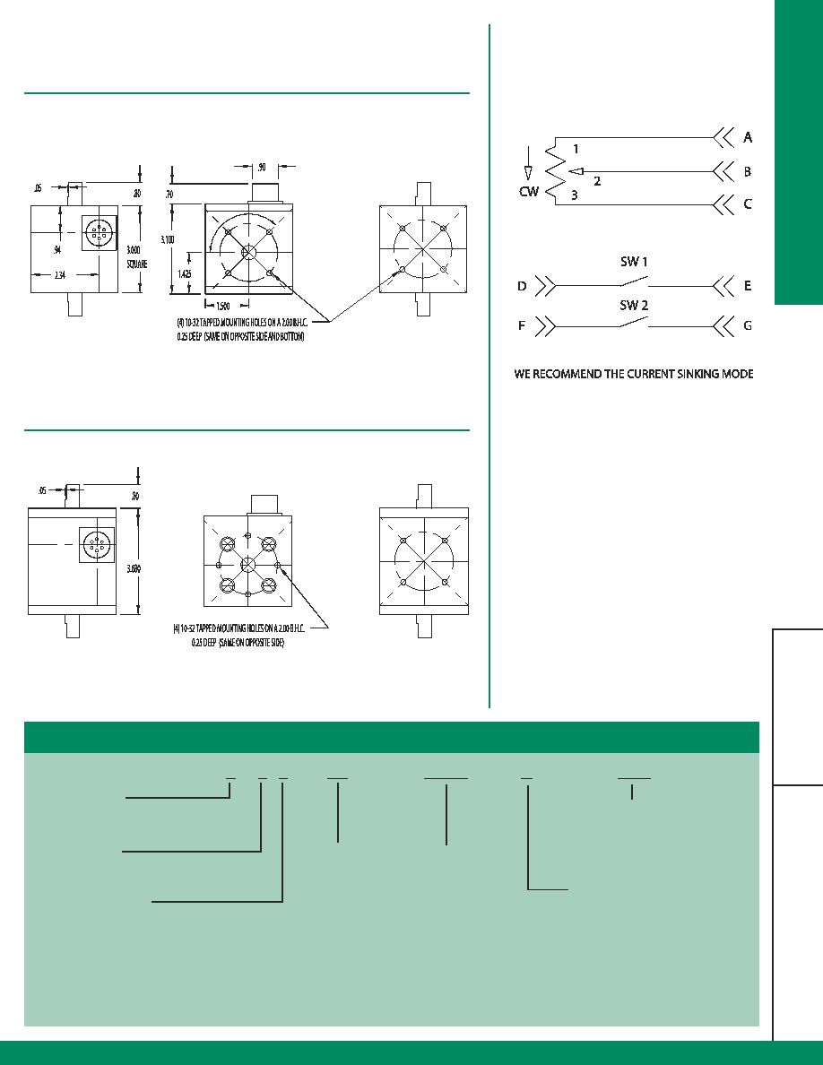
Refer to dimensional drawings
Bearings
3/8" ID, ABEC 5P Shielded
Radial Loading
30 lbs. Operating
Axial Loading
15 lbs. Operating
Mechanical Angle
Continuous
Rotational Life
10,000,000 Cycles Typical
Standard Gear Ratio
1:1 (Others available)
Housing
Black Anodized Aluminum
Weight
Standard: 24 oz., Sealed: 34 oz.
Connector
3, 6 Pin MS3102 or 18" Cable Out
Electrical
Power Rating at 40� C
1 Watt
Dielectric Strength
500 Vac
Resistance Element
Conductive Plastic
Standard Resistance Values
1K, 5K, 10K Ohm
Resistance Tolerance
�10%
Electrical Angle
320� �5�
Wiper Assembly
Precious Metal
Independent Linearity
�1%
Resolution
Essentially
Environmental
Operating Temp.
-55� to +105� C
Temperature Coefficient
�400 ppm/ �C
Vibration
10 to 2000 Hertz at 15 g's
Humidity
100% Relative Humidity
Enclosures (Sealed)
NEMA 4 type - Watertight
(Standard)
NEMA 12/13 equiv. -- Dust-, Oil-Tight
� Enclosure: 3" Cube
� NEMA 12/13 or NEMA 4 type Sealing
� Flush or Flange Base
� Double Shielded ABEC 5 Ball Bearings, Internal
mount provides higher level of reliability
� Steel Gear Drive protects against Shock and
Vibration
� 1:1 Standard Ratio, Others available
� 1K, 5K, 10K Ohm 1W Pots, Continuous
Mechanical Rotation
� Ideal for Dancer Applications
� Limit Switches Option - Rated at 5 amp - 115VAC
standard Gold Crosspoint Contacts Standard
� Operating Temperature Rating: -55� to +105� C
(-67� to +221� F) for harsh industrial environments
For the latest specifications visit our website
www.herculesencoders.com
Hercules Encoders
Specifications
Dimensional Drawings
Wire Drawings
11
He
r
cules
S
eries 7000
Series 7000 Standard
Series 7000 Standard
7 3
1
2 _ -- 1K
--
XXXX
--
C
--
SW1
Shaft Extension
1=Single
2=Double
Mounting Type
1=10-32 BHC on shaft ends and base
2=Flanged base (BHC on shaft ends)
Housing Type
Blank=Standard Housing
S=Sealed (Elastomer)
T=Sealed (PTFE)
Limit Switches
SW1=One Adjustable Limit
Switch
SW2=Two Adjustable Limit
Switches
Ordering Information
Pot Resistance
1K=1K OHM, 1 Watt
5K=5K OHM, 1 Watt
10K=10K OHM, 1Watt
X=Customer Specified
Gear Ratio
Blank=1:1 (Standard)
X=Customer Specified
(Consult Factory)
Connector
Blank=MS 3-Pin (Standard)
6=MS 6 Pin
C=Cable Out
*Gear ratio is available to 1:4.57, i.e., 70� �1� = full pot travel Engineering assistance is
available for determining requirements.
Gear ratio= external shaft rotation: internal potentiometer shaft rotation.