 | –≠–ª–µ–∫—Ç—Ä–æ–Ω–Ω—ã–π –∫–æ–º–ø–æ–Ω–µ–Ω—Ç: AA8622AP | –°–∫–∞—á–∞—Ç—å:  PDF PDF  ZIP ZIP |
2005/7/5
1
Agamem Electronics Inc.
AA8622AP
PRELIMINARY
Dual Video Amplifier
DESCRIPTION
AA8622AP is a dual video amplifier with 6db gain, 75 output buffer and SAG
correction. The 75 buffer is capable of driving two circuits. The SAG could
reduce the output coupling capacitor. The power saving circuit provides the
power saving function. The IC is available in 8-pin TSSOP package .
FEATURES
1. Composite video driver with 6dB gain
2. Dual channels video amplifier
3. Output short circuit protection function
4. SAG correction function
5. A load sufficient for driving two circuits
6. Low operating current, 25mA typical
7. Internal voltage clamp circuit
8. 8-pin TSSOP package
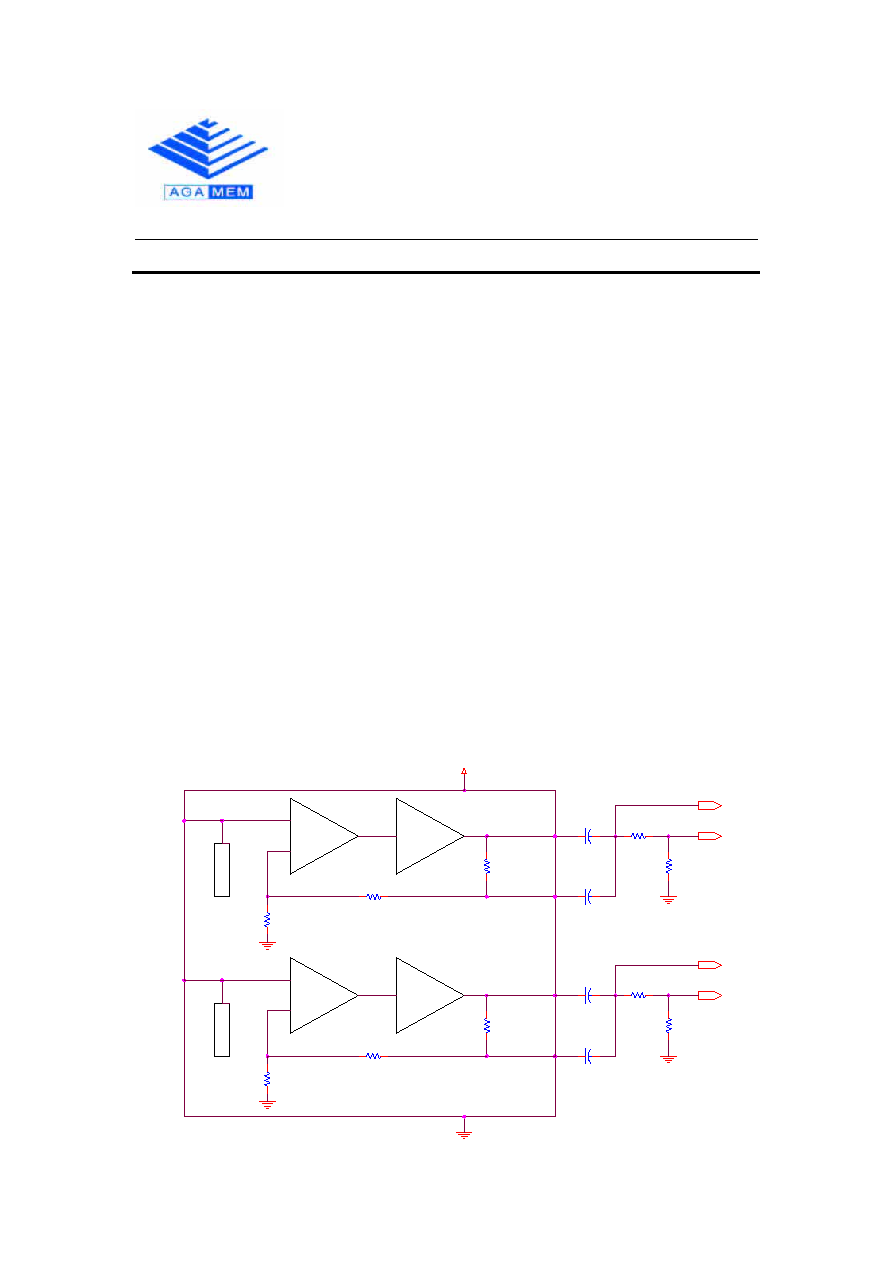
AA8622AP BLOCK DIAGRAM
Vcc
750
2.0K
2.2K
100uF
22uF
75
75
750
100uF
22uF
2.2K
75
75
2.0K
Vout2
Vout2
Vout1
Vout1
CLAMP
6dB
Amp
75
Driver
5
6
Vin2
Vout2
Vsag2
8
(6dB)
CLAMP
6dB
Amp
75
Driver
4
3
Vin1
Vout1
Vsag1
1
(6dB)
7
2
APPLICATION
VCR
Video Camera
TV
Video Player

2005/7/5
2
Agamem Electronics Inc.
AA8622AP
PRELIMINARY
Dual Video Amplifier
PIN DESCRIPTION
Symbol Pin
No Type
Function
Vin1
1 I
Channel1 input terminal of 1V composite signal
GND
2 -
Ground
Vsag1
3
O
Channel 1 SAG correction output
Vout1
4 O
Channel 1 output
Vout2
5 O
Channel 2 output
Vsag2
6
O
Channel 2 SAG correction output
VCC
7
-
5V power supply
Vin2
8 I
Channel 2 input terminal of 1V composite signal
ABSOLUTE MAXIMUM RATING
Ta = 25
Rating
Parameter
Symbol
MIN TYP
MAX
UNIT
CONDITION
Supply Voltage
Vcc
-0.3
5 7 V
Operating
Ambient
Temperature
Ta
-25 75
Storage
Temperature
Ts
-40 125
NOTE :
Stress above those listed under "Absolute Maximum Rating" may cause
permanent damage to the device. This is a stress rating only and functional
operation of the device at these or any other conditions above those
indicated in the operational section of this specification is not implied.
Exposure to absolute maximum rating conditions for the extended periods of
time may affect device reliability.

2005/7/5
3
Agamem Electronics Inc.
AA8622AP
PRELIMINARY
Dual Video Amplifier
ELECTRICAL CHARACTERISTICS
Ta = 25 , Vcc = 5V
Parameter Symbol
Min
Typ
Max
Unit Condition
Supply Current
Icc
25
30
mA No input Signal
Voltage Gain
Gv
5.5 6 6.5
dB
Input Signal Freq =
4.43MHz, 1V
P-P
,
measure V
O1
Frequency
Characteristic
G
F
-1 - 1
dB
Input Signal Freq =
7MHz/1MHz, 1V
P-P
,
measure V
O1
Clamp Voltage
1.9 2.1 2.3 V
Output DC level
1.0 1.2 1.4 V
SAG-Terminal
Gain
G
SAG
35 45 dB
Differential Gain
DG
1 3
%
V
IN
= 1V
P-P,
refer
staircase signal
Differential Phase
DP
1 3
deg
V
IN
= 1V
P-P,
refer
staircase signal
Crosstalk CT
-70
dB
V IN=1V 4.43M
Sinewave

2005/7/5
4
Agamem Electronics Inc.
AA8622AP
PRELIMINARY
Dual
Video
Amplifier
MEASUREMENT CIRCUIT
Tp1
Tp3
Tp5
Tp2
Tp6
Tp4
Vin1
Gnd
Vout1
Vout3
Vin2
Vcc
Vout2
Vout4
75
4.7uF
22uF
100uF
75
75
400
0.6V
1
2
4.7uF
22uF
100uF
75
400
0.6V
1
2
75
75
100uF
1000pF
H
(6dB)
S1
S3
S5
1
2
3
4
Vin1
Gnd
Vsag1
Vout1
Vin2
Vcc
Vsag2
Vout2
H
S6
S4
S2
(6dB)
TEST METHODES
S1
S2
S3
S4
S5
S6
Supply Current
lcc
H
H
7PIN Sink Current
Voltage Gain
Gv
H
H
ON
ON
Vout1 / Vin. Vout2 / Vin2 at Vin1(Vin2)=1MHz, 1Vpp,
Sinewave
Frequency Characteristic
Gf
H
H
ON
ON
Gv1M Voltage Gain at Vin1(Vin2)=1MHz, 1Vpp
Gv10M Voltage Gain at Vin1(Vin2)=7MHz, 1Vpp
Gf=Gv10M-Gv1M
Differential Gain
DG
H
H
ON
ON
Measuring Vout3 at Vin1=Staircase Signal
Differential Phase
DP
H
H
ON
ON
Measuring Vout3 at Vin1=Staircase Signal
Crosstalk
CT
H
L
ON
ON
Vout2 / Vout1 at Vin1=4.43MHz 1Vpp Sinewave
Vout1 / Vin2 at Vin2=4.43MHz 1Vpp Sinewave
Gain Oftest
Gch
H
H
ON
ON
Gv1=Vout1 / Vin1, Gv2=Vout2/Vin2 Gch=Gv1-Gv2
Input Clamp Voltage
Vcl
H
H
Measuring at TP1 (TP2)
SAG Terminal Gain
Gsag
H
H
TP3(TP4) Voltage; V01A(V02A), TP5(TP6) voltage.
Vso1A(Vso2A)
H
H
ON
ON
TP3(TP4) Voltage; V01A(V02A), TP5(TP6) voltage.
Vso1B(Vso2B)
Gsag=20log[(V01B-V01A) / (Vso1A-Vso1B)]
Gsag=20log[(V02B-V02A) / (Vso2A-Vso2B)]
SWITCH CONDITIONS
PARAMETER
SYMBOL
CONDITIONS

2005/7/5
5
Agamem Electronics Inc.
AA8622AP
PRELIMINARY
Dual
Video
Amplifier
TSSOP 8L PACKAGE DIMENSION
NOTES:
1.
Package body sizes exclude mold flash protrusions or gate burrs
2.
Tolerance ± 0.1 (4 mil) unless otherwise specified
3.
Coplanarity:0.1
4.
Controlling dimension is millimeter converted inch dimensions are not necessarily exact
5.
Followed from jedec mo-153
DIMENSIONS IN MILLIMETERS DIMENSIONS IN INCHES
SYMBOLS
MIN NOM MAX MIN
NOM
MAX
A
- - -
- - -
1.20
- - -
- - -
0.048
A1 0.05
-
-
- 0.15
0.002 -
-
- 0.006
A2 0.80
1.00 1.05
0.031 0.039 0.041
b 0.19
-
-
- 0.30
0.007 -
-
- 0.012
C 0.09
-
-
- 0.20
0.004 -
-
- 0.008
D 2.90
3.00 3.10
0.114 0.118 0.122
E 6.20
6.40
6.60
0.244 0.252 0.260
E1 4.30
4.40 4.50
0.169 0.173 0.177
e
- - -
0.65
- - -
- - -
0.026
- - -
L 0.45
0.60
0.75
0.018 0.024 0.030
y
- - -
- - -
0.10
- - -
- - -
0.004
0∞ -
-
- 8∞
0∞ -
-
- 8∞