 | –≠–ª–µ–∫—Ç—Ä–æ–Ω–Ω—ã–π –∫–æ–º–ø–æ–Ω–µ–Ω—Ç: C32025 | –°–∫–∞—á–∞—Ç—å:  PDF PDF  ZIP ZIP |
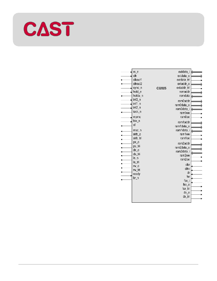
C32025
Digital Signal Processor
Megafunction
CAST, Inc.
May 2004
Page 1
General Description
The C32025 is a 16-bit fixed-point digital signal
processor core. It combines the flexibility of a
high-speed controller with the numerical
capability of an array processor. The C32025 has
the same instruction set as the TMS320C25 and
also provides the same interrupts, serial interface
and timer.
Developed for easy reuse with ASICs or FPGAs,
the core requires under 18000 ASIC gates.
Applications
∑
Digital sound processing (adaptive filtering,
FFT, other special sound effects)
∑
Voice recognition
∑
Telecommunications (modems, codecs)
∑
Medical equipment (diagnostics tools)
∑
Computers peripherals
∑
Various embedded data-intensive systems
Symbol

C32025 Megafunction Datasheet
CAST, Inc.
Page
2
Features
∑
Control Unit
o 16-bit instruction decoding
o Repeat instructions for efficient use
of program space and enhanced
execution
∑
Central Arithmetic-Logic Unit
o 16-bit parallel shifter; 32-bit
arithmetic and logical operations
o 16 x 16 bit parallel multiplier with a
32-bit product
o 32-bit accumulator with output
shifter
o Single-cycle Multiply-and-
Accumulate instructions
∑
Auxiliary Registers
o 8 16-bit registers for indirect
addressing or temporary data
storage
o 16-bit Auxiliary Register Arithmetic
Unit including operations with
reversed-carry propagation
∑
Memory addressing modes
o Direct - using a 9-bit Page Pointer
and instruction word's lowest 7-bits
o Indirect ≠ using the Auxiliary
Register File
o Immediate ≠ less than 16-bit via
instruction word or full 16-bit long
immediate following the instruction
word
o Block moves for data/program
management
∑
8-level Hardware Stack
∑
Interrupt Controller: 6 interrupt sources,
excluding reset and a software interrupt
∑
Synchronous serial port for direct codec
interface
∑
16-bit reload timer
∑
Program Memory organization
o 4K-words of internal ROM
o Internal 256-word RAM block
configurable either as program or
data space
o 64K-word external program space
∑
Data Memory organization
o 2 Internal 256-word and one 32-
word RAM blocks
o 64K-words of external data space
o 6 memory mapped registers
∑
16 Input and 16 Output channels
∑
Wait states for interfacing slower off-chip
devices
∑
Multiprocessing support
o Global data memory interface
o Synchronization input for
synchronous multiprocessor
configurations
∑
Concurrent DMA using an extended Hold
operation
∑
Design is strictly synchronous with positive-
edge clocking and synchronous reset, no
internal tri-states.
C32025 Megafunction Datasheet
CAST, Inc.
May 2004
Page 3
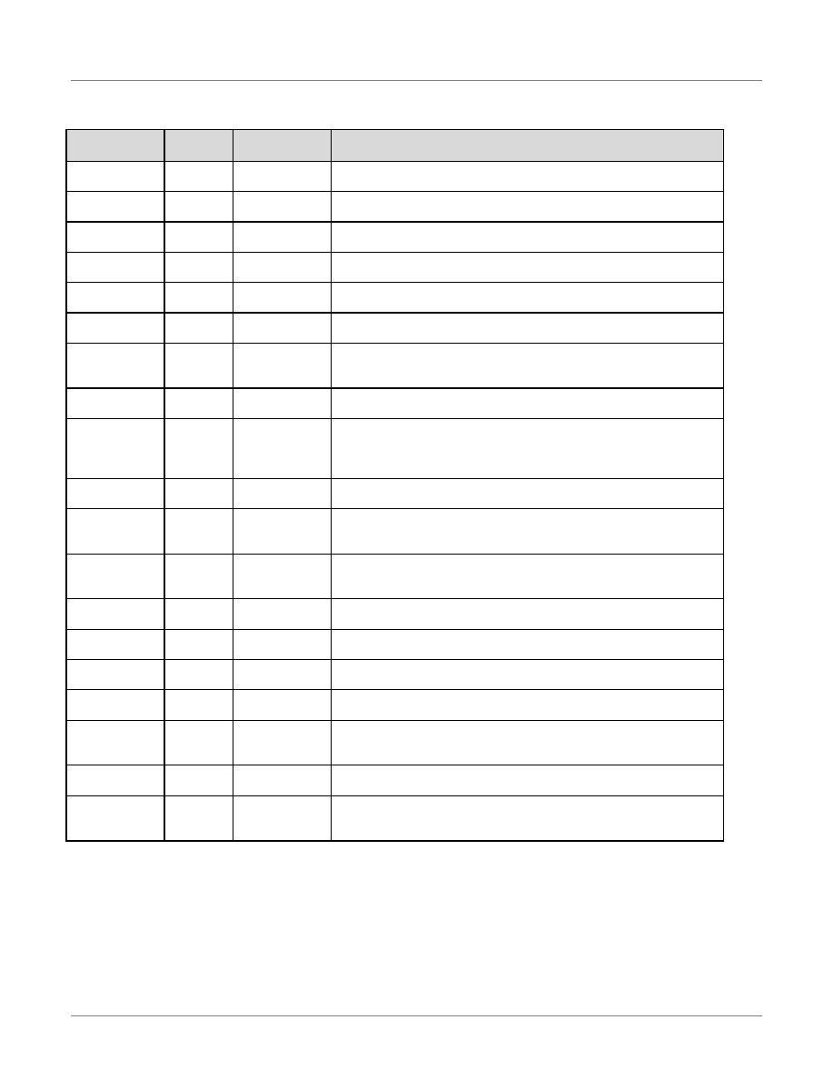
Pin Description
Name
Type
Polarity/
Bus size
Description
clk I
Rise
Master clock input
All internal synchronous circuits clock
clkout1 O -
Master clock output (fclk/4)
When High it indicates internal quarter-phases Q3 and Q4
clkout2 O -
Second clock output (fclk/4)
When High it indicates internal quarter-phases Q2 and Q3
rs_n I
Low Hardware reset input
Active for 2 cycles resets the device
mpmc I -
Microprocessor/microcomputer mode
When Low the internal ROM is mapped into program space
sync_n I Fall
Synchronization input
Forces the internal quarter-phase to Q1
hold_n I Low Hold input
Forces processor to place the data & address buses and control lines
in the hi-Z state
holda_n O Low
Hold acknowledge output
Indicates that processor is in the hold mode
int0_n
int1_n
int2_n
I
I
I
Low/Fall
Low/Fall
Low/Fall
External interrupt inputs
External interrupt 0
External interrupt 1
External interrupt 2
iack_n I Low Interrupt acknowledge
Indicates branching to the interrupt vector
ps_o
ds_o
is_o
O
O
O
Low
Low
Low
Program, data and I/O space select signals
ps_tri
ds_tri
is_tri
O
O
O
High
High
High
Select signals tri-state control
Enables external tri-state buffers
rw_o O
-
Read/write output signal
Indicates external transfer direction. High means reading
rw_tri O H
Read/write tri-state control
Enables external tri-state buffer
strb_o O Low Strobe signal
Low indicates an external bus cycle
strb_tri O High Strobe tri-state control signal
Enables external tri-state buffer
ready I High Data ready input
Indicates that external device is prepared for transfer to be
completed
bio_n I Low Branch control input
When active the BIOZ branch occurs
br_n O
Low Bus request output
Asserted when the processor requires access to external global data
memory space
C32025 Megafunction Datasheet
CAST, Inc.
Page
4
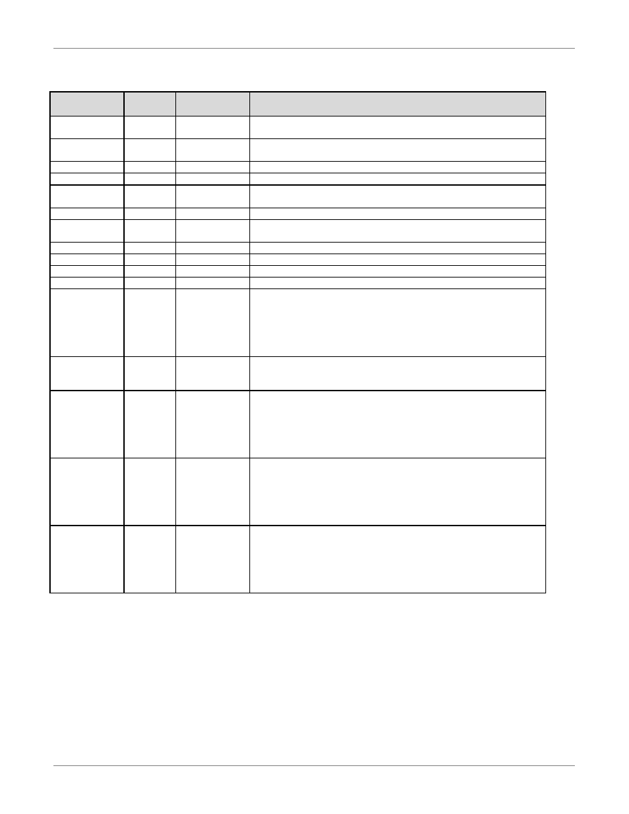
Name
Type
Polarity/
Bus size
Description
msc_n O Low Microstate complete output
Indicates a completion of a memory operation
xf O
- External flag output
General purpose output pin
clkr I
Fall Receive clock input
clkx I
Rise Transmit clock input
dr I
- Serial data receive input
Data clocked by clkr
dx_o O
-
Serial data transmit output
dx_tri O High Serial transmit tri-state control
Active only while transmitting
fsr I
Fall Frame synchronization pulse for receive input
fsx_i I
Fall Frame synchronization pulse for transmit input
fsx_o O
Fall Frame synchronization pulse for transmit output
fsx_tri O High Frame synchronization pulse for transmit tri-state control
extaddr_o
extaddr_tri
extdata_i
extdata_o
extdata_tri
O
O
I
O
O
16
High
16
16
High
External Program/ Data/ IO interface
Address bus output
Address tri-state control
Data bus input
Data bus output
Data bus tri-state control
romdata
romaddr
I
O
16
12
Internal Program Memory interface
Data input
Address output
ram0data_i
ram0data_o
ram0addr
ram0we
ram0oe
I
O
O
O
O
16
16
8
High
High
Internal RAM 0 interface
Data bus input
Data bus output
Data file address
Data file write enable
Data file output enable
ram1data_i
ram1data_o
ram1addr
ram1we
ram1oe
I
O
O
O
O
16
16
8
High
High
Internal RAM 1 interface
Data bus input
Data bus output
Data file address
Data file write enable
Data file output enable
ram2data_i
ram2data_o
ram2addr
ram2we
ram2oe
I
O
O
O
O
16
16
5
High
High
Internal RAM 2 interface
Data bus input
Data bus output
Data file address
Data file write enable
Data file output enable
C32025 Megafunction Datasheet
CAST, Inc.
Page
5
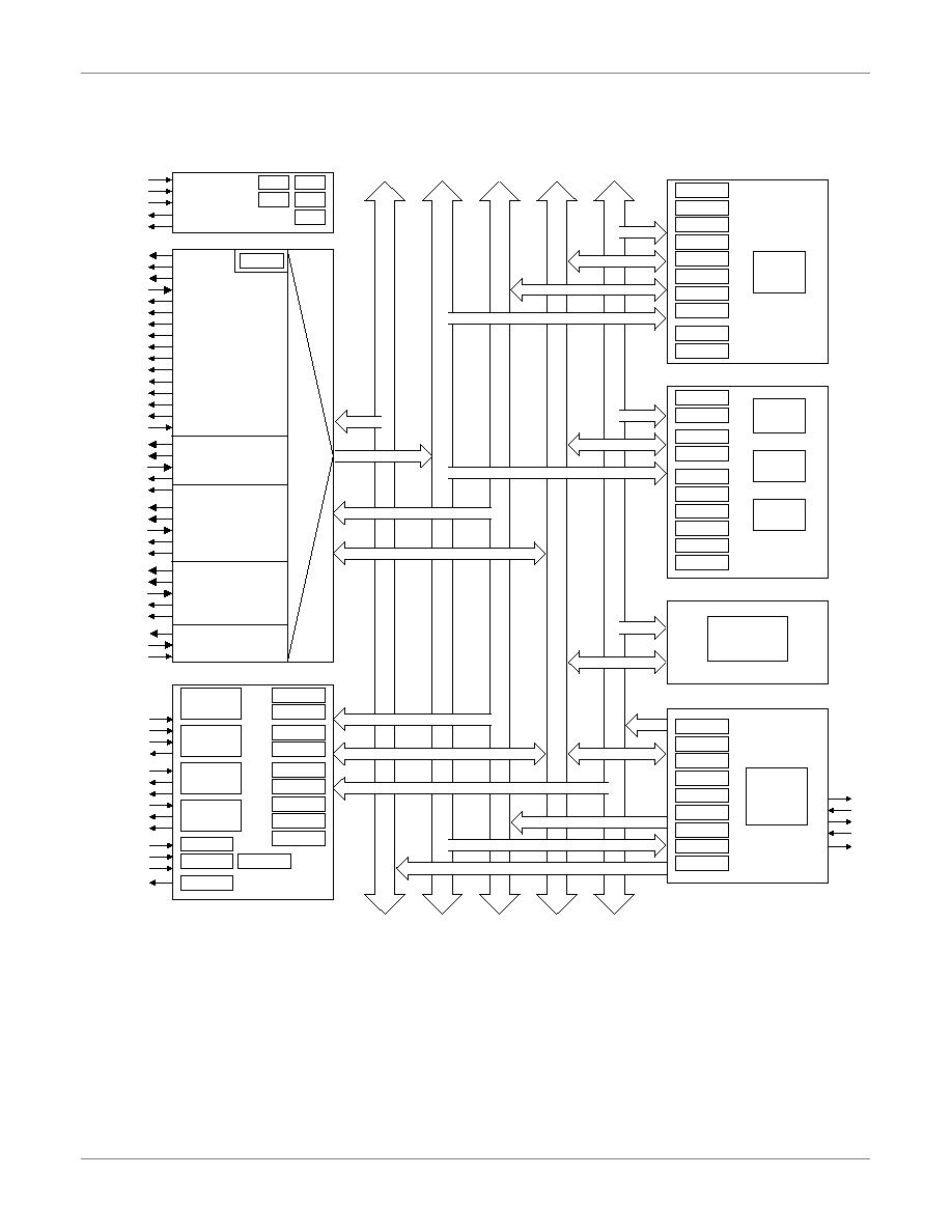
Block Diagram
Phase Generator
Reset Control
Control Unit
Interrupt Controller
Peripherals
Auxiliary
Registers Unit
Central
Arithmetic
Logic Unit
Stack Unit
clk
rs_n
sync_n
clkout1
clkout2
u_phasegenerator
extaddr_o
extdata_o
extdata_i
extdata_tri
rw_o
strb_o
ds_o
ps_o
is_o
ready
ram0addr
ram0data_o
ram0data_i
ram0oe
ram0we
ram1addr
ram1data_o
ram1data_i
ram1oe
ram1we
ram2addr
ram2data_o
ram2data_i
ram2oe
ram2we
romaddr
romdata
u_memdrivers
extaddr_tri
rw_tri
strb_tri
ds_tri
ps_tri
is_tri
xf_o
hold_n
holda_n
bio_n
mpmc
msc_n
u_control
u_irqdrivers
br_n
int2_n
int1_n
int0_n
iack_n
clkx
dx_o
dx_tri
fsx_i
fsx_o
fsx_tri
clkr
dr
fsr
q1
q2
q3
q4
rst
external bus
interface
block 0
interface
block 1
interface
block 2
interface
internal ROM
interface
pc_reg
pfc_reg
qir_reg
ir_reg
rptc_reg
mcs_reg
dp_reg
FSM
control unit
st1_hm
st1_xf
external
interrupts
serial port
transmitter
serial port
receiver
timer
tim_reg
prd_reg
drr_reg
rsr_reg
dxr_reg
xsr_reg
st0_intm
st1_fo
st1_txm
st1_fsm
imr_reg
ifr_reg
greg_reg
u_auxreg
ar0_reg
ar1_reg
ar2_reg
ar3_reg
ar4_reg
ar5_reg
ar6_reg
ar7_reg
st0_arp
st1_arb
arau
u_calu
acch_reg
accl_reg
st1_sxm
st1_c
st1_tc
st0_ov
st0_ovm
st1_pm
tr_reg
pr_reg
ALU
multiplier
shifters
u_stack
hardware
stack
p
r
o
g
a
d
d
r
p
r
o
g
b
u
s
d
a
ta
a
d
d
r
d
a
t
a
b
u
s
(
u_
da
t
a
m
u
x
)
i
n
st
r
u
ct
i
o
n
s
st1_cnf
Memory Control Unit
C32025 Block Diagram