S
ilicore
SHAOXING SILICORE TECHNOLOGY CO.,LTD
www. Silicore. com. cn
CHMC
1/7
2.4W AUDIO AMPLIFIER, SIF AMPLIFIER AND
DETECTOR FOR TV SILICON MONOLITHIC
BIPOLAR INTEGRATED DIRCUIT CD1353CP
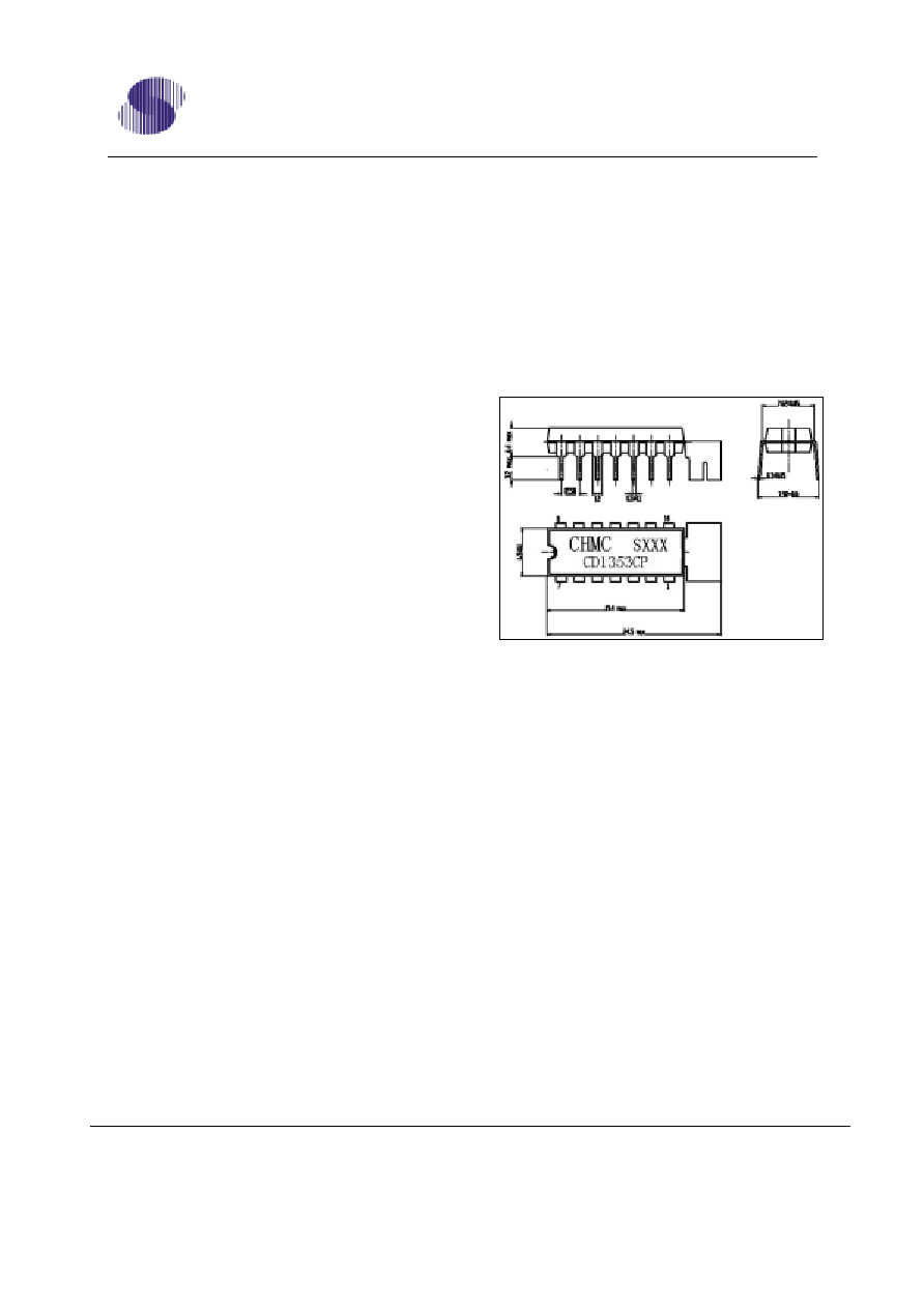
DESCRIPTION Outline Drawing
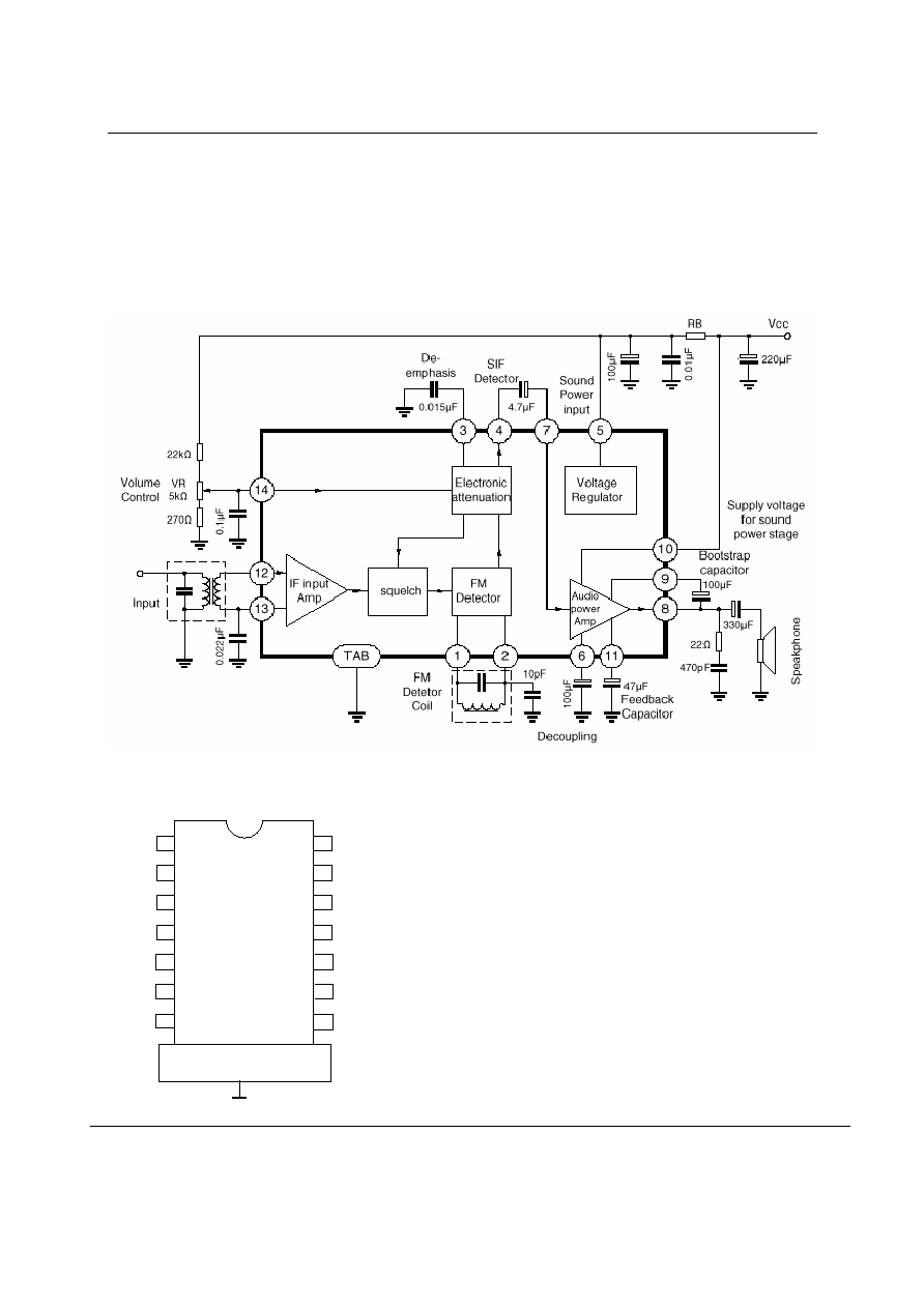
The CD1353CP is a silicon monolithic
integrated circuit designed for SIF and Audio
section in television receivers. This IC has
all functions including sound IF Amplifier,
FM Detector, DC volume control circuit,
Audio Output amplifier with 2.4W output
power and voltage regulator.
This IC is encapsulated in 14pin dual
in-line package with heat tab.
FEATURES:
All functions for SIF and audio stage are provided by this one-chip IC and this IC
will realize reduction of assembly cost as well as reduction of number of other
components.
Audio output power is controlled by electronic attenuation circuit which operate
at DC. Therefore, unnecessary radiation, oscillation etc. are eliminated. Due to
DC control, shielded wire is not required and variable resistor will be placed
anywhere required.
Electronic attenuator has enough attenu ation (Typ.80dB) by the adoption of
squelch circuit. In addition, as attenuation characteristic is same with resistance
change of variable resistor, suitable variable resistor will be selected easily.
As Peak differential detection method is adopted for FM detection, outside
circuitry can be very simple easy.
As operation voltage (Vcc) range for output stage is very wide (9-18V), suitable
Vcc can be freely determined for required output level.

Silicore
CD1353CP
SHAOXING SILICORE TECHNOLOGY CO.,LTD
www. Silicore. com. cn
CHMC
4/7
ELECTRICAL CHARACTERISTICS
(Ta=25�3�C)
Characteristic Symbol
Test
Condition
Min
Typ
Max
Unit
If Stage (Vcc=12V R
B
=100 Rg=50 V141.3V fo=4.5MHz f
M
=400Hz f=�25kHz)
Pin 5 Voltage
V
5 A
7.5
8.0
8.5
V
Pin 5 Voltage
V
5 B
Vcc=18V
R
B
=330 7.5
8.0
8.5 V
Pin 10 Current
I
1 0 A
No Input Signal
14
19
24
mA
Pin 10 Current
I
1 0 B
Vcc=18V R
B
=330No
Input Signal
16 28 35 mA
IF Limiting Voltage
Vi(lim) V
O A F
(Vi=10mVrms)-3dB
200
400
�Vrms
Detector Output Voltage
V
O D
Vi=10mVrms
300
360
mVrms
Detector Distortion
THD1
Vi=10mVrms
0.7
%
AM Rejection
AMR
AM MOD 30%
f
M
=400Hz Vi=10mVrms
-40 -50
dB
Maximum Attenuation
ATT
M A X
V14=0V -60
-80
dB
Sound Power Stage (vcc=12V R
B
=100 R
L
=8 f=400Hz Rg=600)
Sound Stage Voltage Gain
Av
Vi=30mVrms
33
37
41
dB
Sound Output Power
P
O 1
THD=10%
0.9
1.2
W
Sound Output Power
P
O 2
Vcc=18V R
B
=330
THD=10%
2.0 2.4
W
Sound Output Distortion
THD2
Po=0.5W
0.6 2.0
%
Sound Output Distortion
THD3
Vcc=18V R
B
=330
Po=0.5W
0.5
2.0 %
If Stage + Sound Power Stage
Over All Sound Output
Distortion
THD4 Po=0.5W
Vi=10mVrms
1.5 4.0 %
Reference Data
Pin 10 Current
I
1 0
THD.2A=10%
200
210
mA
Pin 10 Current
I
1 0
THD.2B=10%
270
280
mA
Sound Output Power
Po
1
THD=3%
1.1
W
Sound Output Power
Po
2
Vcc=18V R
B
=330
THD=3%
2.0 W
Sound Stage Band Width
BW
-3dB
50
50k
Hz
fo=4.5MHz
5.5MHz 6.0MHz 6.5MHz
Pin Inpedance
R C R C R C R C
Unit
Pin 12 IF Input
2
9.5
2
9.4
1.9
9.4
1.9
9.4 k/pF
Pin 1 Detector
Connect
2.4 6.3 2.4 6.2 2.4 6.1 2.4 6.1 k/pF
Pin2 Detector Connect 11.5
9
9
8.5
8.5
8.3
7.8
8.1 k/pF