 | –≠–ª–µ–∫—Ç—Ä–æ–Ω–Ω—ã–π –∫–æ–º–ø–æ–Ω–µ–Ω—Ç: DCH0512D | –°–∫–∞—á–∞—Ç—å:  PDF PDF  ZIP ZIP |
B4-31
DCH SERIES
3 WATT
F
EATURES
∑ ≠55∞C to 100∞C
∑ 4 to 6.5, 9 to 15, or
20 to 32 VDC input
∑ Fully isolated
∑ Output regulated from
input side
∑ 100 kHz typical switching
frequency
∑ Topology ≠
Push-Pull DC/DC Converter
∑ Up to 75% efficiency
∑ No minimum load
∑ Output capacitor suggested
MODELS
VDC O
UTPUT
DESCRIPTION
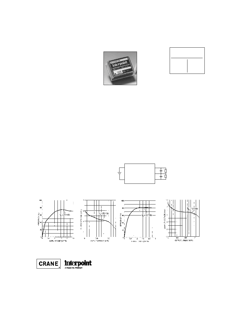
The DCH SeriesTM offers isolated, unregulated DC/DC converters
with up to 3 watts of output power in a low profile (0.350 max.) metal
package. Single and dual output models are available with input
voltages of 5, 12, or 28 VDC. DCH Series converters operate over
a ≠55∞C to +100∞C temperature range.
DCH Series converters use a non-saturating core circuit operating
at a frequency of approximately 100 kHz, which reduces reflected
input ripple and minimizes EMI/RFI problems. For applications
requiring MIL-STD-461C, CEO3, reflected input ripple levels, refer
to Section B5 or contact your Interpoint representative for matching
EMI filters.
Figure 1 shows a standard connection scheme for a dual output
model. Users may also elect to use a dual output device to provide
a single output at double the rated output voltage. The double
voltage connection is achieved by leaving the normal output
common pin (Pin 15) unconnected and using either the positive or
negative Vout pin for the output common connection.
On all DCH Series models, a tantalum capacitor with a minimum
value of 22 µF and an appropriate voltage rating should be
connected between the output common and the output line(s) to
minimize output ripple.
SINGLES
5
12
28
DUALS
±12
±15
±28
DC/DC C
ONVERTERS
5, 12,
OR
28 V
OLT
I
NPUT
Output Current vs Output Voltage
DCH2805S
F
IGURE
3
Negative
Output
28 V
Load
Load
+
+
Input
Common
Positive
Input
Positive
Output
Output Common
Efficiency
DCH2805S
F
IGURE
2
Efficiency
DCH1215D
F
IGURE
4
Output Current vs Output Voltage
DCH1215D
F
IGURE
5
Size (max.): 0.975 x 0.800 x 0.350 inches (24.77 x 20.32 x 8.89 mm)
See section B8, case A3, for dimensions.
Weight:
20 grams typical
Screening:
Standard or ES. See Section C2 for screening options,
see Section A5 for ordering information.
F
IGURE
1:
D
UAL
DCH C
ONVERTER
WITH
E
XTERNAL
C
APACITORS
Typical Performance Curves: 25∞C Tc ,nominal Vin
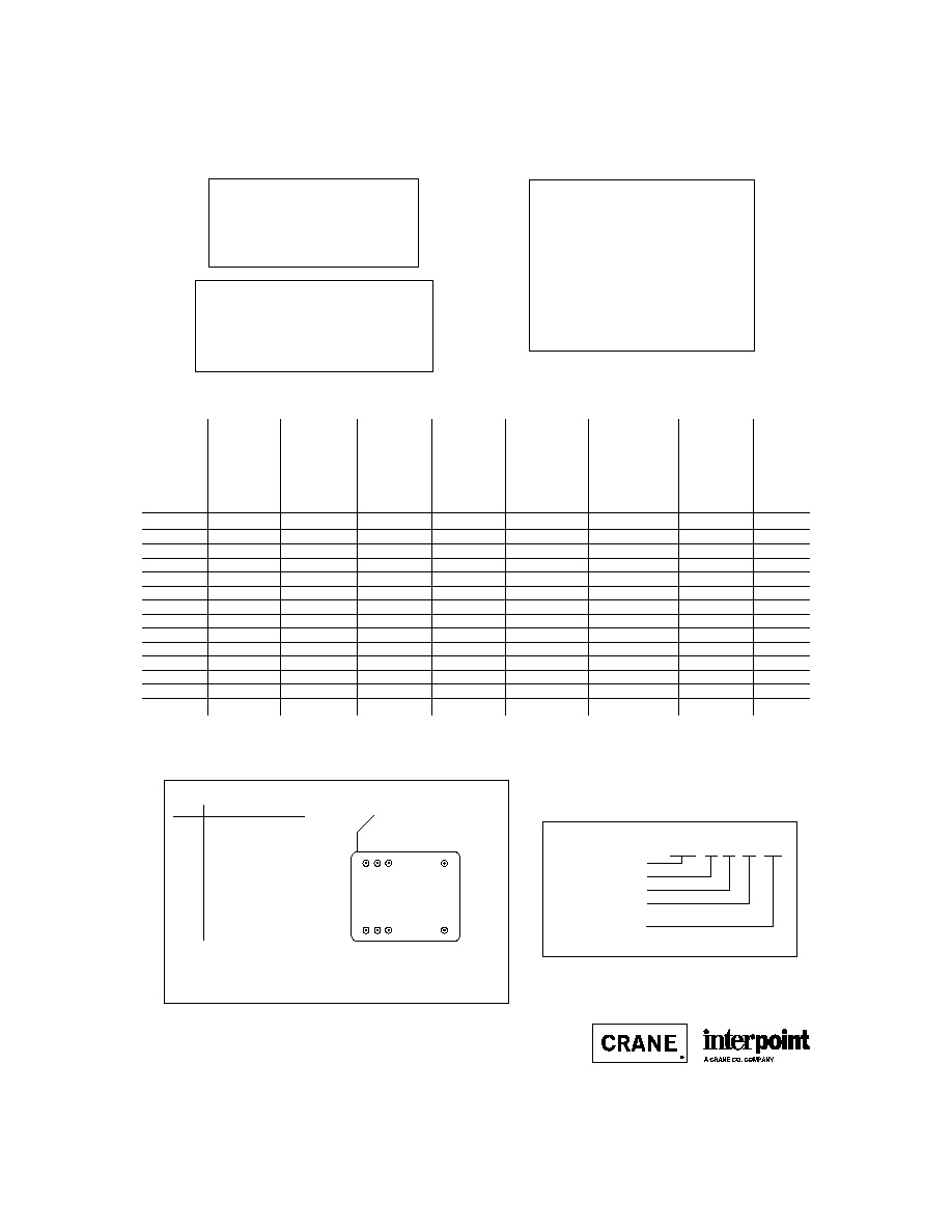
TYPICAL CHARACTERISTIC
RECOMMENDED OPERATING CONDITION
ABSOLUTE MAXIMUM RATING
OUTPUT
OUTPUT
LOAD
MODEL
INPUT
OUTPUT CURRENT
POWER
EFFICIENCY
REGULATION
INPUT
OUTPUT
NUMBER
VOLTAGE
VOLTAGE
1
T
C
= ≠55∞C
T
C
= ≠55∞C
FULL LOAD
50% TO
CURRENT
2
RIPPLE
2
TO +100∞C
TO +100∞C
FULL LOAD
10% LOAD
NOMINAL
NOMINAL
MAX
MAX
MIN
TYP
MAX
MAX
VDC
VDC
mA
W
%
mV
mA
mVp-p
DCH0505S
5
5
400
2.0
67
470
220
300
DCH0512S
5
12
208
2.5
72
830
250
200
DCH0512D
5
±12
±104
2.5
72
830
250
100
DCH0515D
5
±15
±83
2.5
72
830
250
100
DCH1205S
12
5
500
2.5
70
500
110
300
DCH1212S
12
12
250
3.0
72
440
70
200
DCH1228S
12
28
107
3.0
75
870
110
300
DCH1212D
12
±12
±125
3.0
72
440
110
100
DCH1215D
12
±15
±100
3.0
72
440
110
100
DCH1228D
12
±28
±53
3.0
75
870
110
200
DCH2805S
28
5
500
2.5
68
450
50
300
DCH2812S
28
12
250
3.0
75
375
50
200
DCH2812D
28
±12
±125
3.0
75
375
50
100
DCH2815D
28
±15
±100
3.0
75
375
50
100
B4-32
DCH SERIES
3 WATT
DC/DC C
ONVERTERS
Output Voltage Tolerance (Full Load)
∑ 5 volt output models
±0.25
∑ 12 volt output models
±0.4
∑ 15 volt output models
±0.5
∑ 28 volt output models
±0.6
Line Regulation
∑ Output is directly proportional to input voltage.
Output Voltage Temperature Coefficient
∑ 0.02%/∞C maximum
Converter Frequency
∑ 100 kHz typical
Isolation
∑ 100 megohm minimum at 500 V
Note
1. Pins 14 and 15 are connected
internally on single output
models.
Notes
1. Nominal output voltage is correct only for nominal input voltage. Output voltage changes in proportion to input voltage.
2. Output ripple results require the connection of a tantalum capacitor (22 µF minimum) across each output.
Pin
Designation
1
Positive Input
2
No Connection
3
Input Common
8
No Connection
9
Case
14
Negative Output
1
15
Output Common
1
16
Positive Output
Output Power
∑ 3 watts
Lead Soldering Temperature (10 sec per lead)
∑ 300∞C
Storage Temperature Range (Case)
∑ ≠55∞C to +125∞C
Input Voltage Range (VDC)
∑ 5 volt input models
4.0 to 6.5
∑ 12 volt input models
9.0 to 15.0
∑ 28 volt input models
20.0 to 32.0
Case Operating Temperature (Tc)
∑ ≠55∞C to +100∞C full power
PIN OUT
BOTTOM VIEW
DCH
Dot on top of cover
indicates pin one.
1
8
16
9
2 3
14
15
See Section B8, case A3, for dimensions
DCH 28 12 D / ES
Base Model
Input Voltage
Output Voltage
Number of Outputs
(S = single, D = dual)
Screening
(Standard screening has no designator
in this position.)
MODEL NUMBERING KEY
F
IGURE
6: P
IN
O
UT
Electrical Characteristics: 25∞C Tc, 28 VDC Vin, 100% load, unless otherwise specified.
24600-001-DTS Rev A
DQ# 1024
All technical information is believed to be accurate, but no responsibility is
assumed for errors or omissions. Interpoint reserves the right to make changes in
products or specifications without notice. DCH Series is a trademark of Interpoint.
Copyright © 1991 - 1999 Interpoint. All rights reserved.
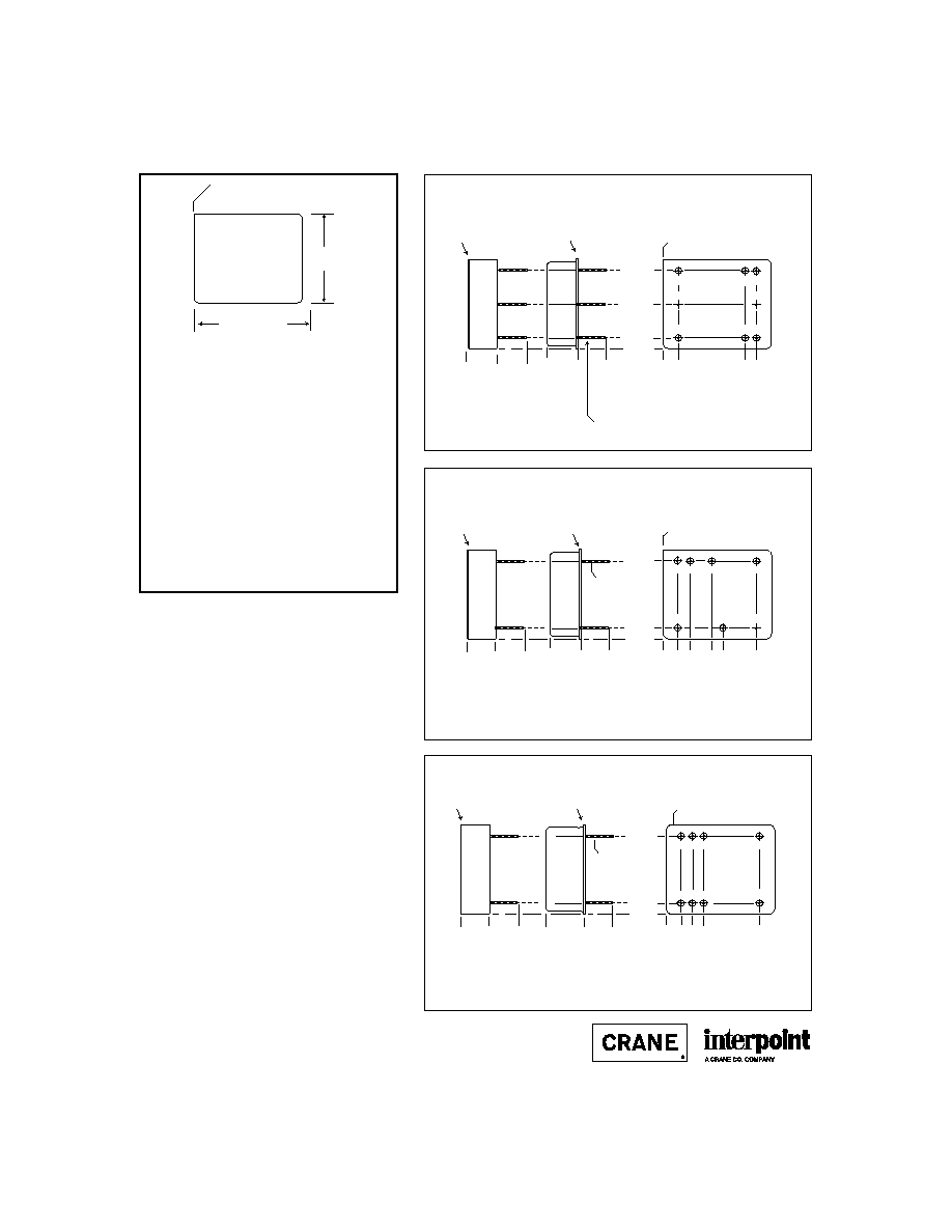
B8-6
CASE A
C
ASES
CASE A
BOTTOM VIEW
See Figures 2 - 4
for pin configurations.
Dot on top of case
indicates pin one.
0.975 max
(24.77)
0.800 max
(20.32)
Materials
Header
Kovar/Nickel/Gold
(Case A3, Kovar/Nickel)
Cover Kovar/Nickel
Pins Kovar/Nickel/Gold,
matched glass seal
Case dimensions in inches (mm)
Tolerance
±
0.005 (0.13) for three decimal places
±
0.01 (0.3) for two decimal places
unless otherwise specified
CAUTION
Heat from reflow or wave soldering may damage
the device. Solder pins individually with heat
application not exceeding 300
∞
C for 10 seconds
per pin.
0.000
0.097
(2.46)
0.697
(17.70
Squared corner and dot on
top of case indicate pin one.
0.397
(10.08)
0.000
0.135 (3.43)
0.835 (21.21)
0.270 max
(6.98)
0.000
0.735 (18.67)
Projection Weld
Seam Seal
FMSA EMI Filter: Screening ≠ Standard, ES, or 883
STF EMI Filter: Screening ≠ Space Standard, H, or K
1
3
8
4
7
2
6 5
BOTTOM VIEW CASE A1
0.270 max
(6.86)
0.000
0.27
±
0.02
(6.9
±
0.5)
0.27
±
0.02
(6.9
±
0.5)
0.018
±
0.002 dia.
(0.46
±
0.05)
0.000
0.097
(2.46)
0.697
(17.70
0.000
0.135 (3.43)
0.835 (21.21)
0.270 max
(6.98)
0.000
1
4
7
5
2
3
6
0.235 (5.97)
0.435
(11.05)
0.535 (13.59)
MCH Series: Screening ≠ Standard, ES, or 883
SLH Series: Screening ≠ Space Standard, H, or K
BOTTOM VIEW CASE A2
0.270 max
(6.86)
0.000
0.27
±
0.02
(6.9
±
0.5)
0.27
±
0.02
(6.9
±
0.5)
Projection Weld
Seam Seal
Squared corner and dot on
top of case indicate pin one.
0.018
±
0.002 dia.
(0.46
±
0.05)
0.000
0.097
(2.46)
0.697
(17.70
0.000
0.135 (3.43)
0.835 (21.21)
1
8
16
9
2 3
0.235 (5.97)
14
15
DCH Series: Screening ≠ Standard or ES
0.335 (8.51)
BOTTOM VIEW CASE A3
0.350 max
(8.89)
0.350 max
(8.89)
0.000
0.27
±
0.02
(6.9
±
0.5)
0.018
±
0.002 dia.
(0.46
±
0.05)
Projection Weld
Dot on top of case
indicates pin one.
0.000
0.27
±
0.02
(6.9
±
0.5)
Seam Seal
F
IGURE
2: C
ASE
A1
F
IGURE
3: C
ASE
A2
F
IGURE
4: C
ASE
A3
F
IGURE
1: C
ASE
A M
AXIMUM
D
IMENSIONS
Note: Although every effort has been made to render the case
drawings at actual size, variations in the printing process may
cause some distortion. Please refer to the numerical dimensions
for accuracy.
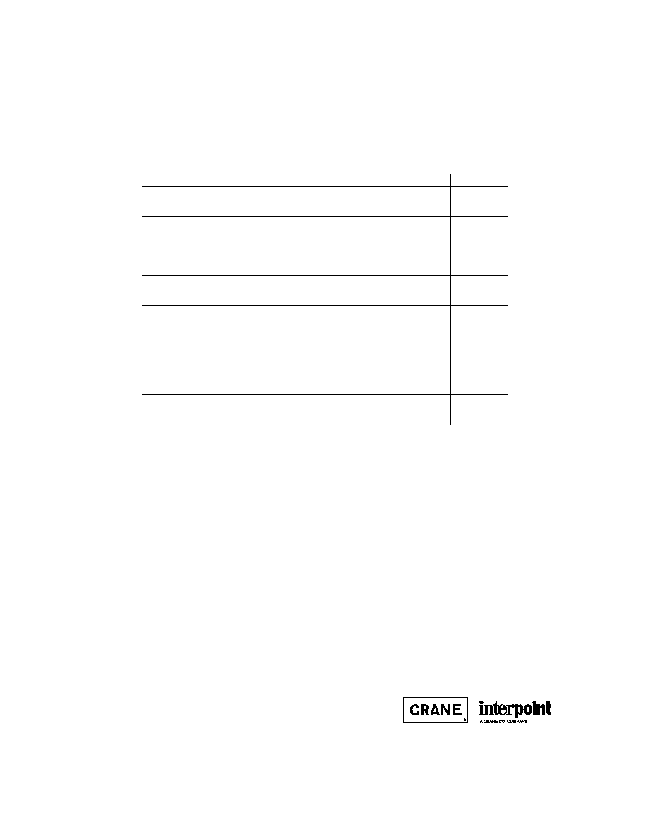
C2-12
QA SCREENING
85∞C PRODUCTS
TEST (85∞C Products excluding HR products)
STANDARD
/ES
PRE-CAP INSPECTION
Method 2017
yes
yes
TEMPERATURE CYCLE (10 times)
Method 1010, Cond. B, -55∞C to 125∞C
no
yes
CONSTANT ACCELERATION
Method 2001, 500 g
no
yes
BURN-IN
96 hours at 70∞C ambient (typical)
no
yes
FINAL ELECTRICAL TEST MIL-PRF-38534, Group A
Subgroups 1 and 4: +25∞C case
yes
yes
HERMETICITY TESTING
Fine Leak, Method 1014, Cond. A
no
yes
Gross Leak, Method 1014, Cond. C
no
yes
Gross Leak, Dip (1 x 10
-3
)
yes
no
FINAL VISUAL INSPECTION
Method 2009
yes
yes
Test methods are referenced to MIL-STD-883 as determined by MIL-PRF-38534.
MFW Series
MTW Series
MHE/MLP Series
MHL Series
MRH Series
MTO Series
MSR Series
DCH Series
FM/FMA/FMB EMI Filters
MSF EMI Filter
85∞C P
RODUCTS
Applies to the following products: