ES1AM thru ES1MM
Crownpo Technology
Document No. 12086
www.crownpo.com
01-Apr-04
Surface Mount Ultrafast Plastic Rectifier
Reverse Voltage 50 to 1000V
1.0A
Maximum Ratings & Thermal Characteristics
Ratings at 25
-
C ambient temperature unless otherwise specified.
ES1AM ES1BM ES1DM ES1GM ES1JM ES1KM ES1MM
Symbols
Units
Maximum repetitive peak reverse voltage
V
RRM
50
100
200
400
600
800
1000
V
Maximum RMS voltage
V
RMS
35
70
140
280
420
560
700
V
Maximum DC blocking voltage
V
DC
50
100
200
400
600
800
1000
Maximum average forward rectified current
0.375" (9.5mm) lead length at T
A
=55
-
C
I
F(AV)
1.0
A
Peak forward surge current
8.3ms single half sine-wave superimposed on
I
FSM
30
A
rated load (JEDEC Method)
Typical thermal resistance
(1)
R
JA
32
-
C/W
Operating junction and storage temperature range
T
J
, T
STG
-55 to +150
-
C
-
C
Electrical Characteristics
Ratings at 25
-
C ambient temperature unless otherwise specified.
Symbols
Units
Maximum instantaneous forward voltage at 1.0A
(2)
V
F
1.3
1.7
V
Maximum DC reverse current
T
A
= 25
-
C
I
R
5.0
A
at rated DC blocking voltage
T
A
=100
-
C
150
Maximum reverse recovery time
I
F
=0.5A, I
R
=1.0A, I
rr
= 0.25A
t
rr
50
75
ns
Typical junction capacitance at 4.0V, 1MHz
C
J
20
pF
Notes:
(1) Thermal resistance from junction to ambient at 0.375
"
(9.5mm) lead length
(2) Pulse test: 300
e
s pulse width, 1% duty cycle
e
V
1.0
Parameter
Device marking code
H1 H2 H3 H4 H5 H6 H7
ES1AM ES1BM ES1DM ES1GM ES1JM ES1KM ES1MM
Features
N
Plastic package has Underwriters Laboratories
Flammability Classification 94V-0
N
For surface mount applications
N
Ultrafast recovery time for high efficiency
N
Glass passivated chip juctions
N
Low Vf, low power loss
N
High temperature soldering guaranteed:
250
-
C/10 seconds on terminals
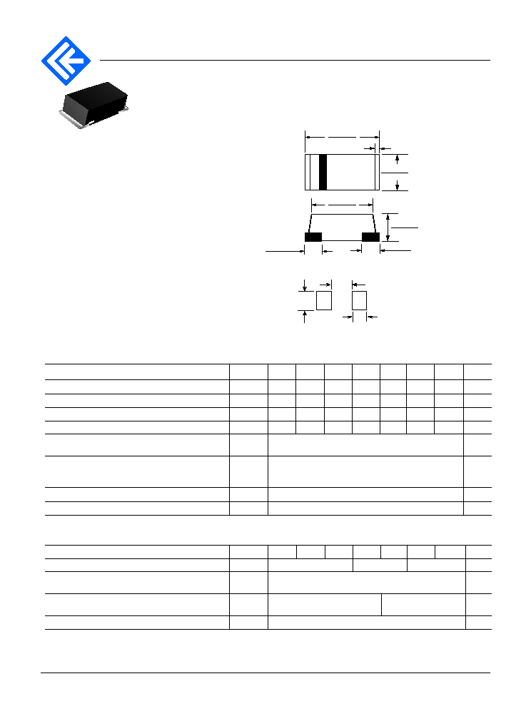
Mechanical Data
Case: JEDEC SOD123/Mini SMA molded plastic
Terminals: Solderable per
MIL-STD-750, Method 2026
Polarity: Color band denotes cathode end
Weight: 0.05g
N
Low profile package
N
Easy pick and place
Mounting Pad Layout
0.076 (1.93)
0.071 (1.8)
0.055 (1.4)
0.161 (4.1)
0.146 (3.7)
SOD-123
0.012 (0.3) Typ.
0.071 (1.8)
0.055 (1.4)
0.063 (1.6)
0.055 (1.4)
0.110 (2.8)
0.094 (2.4)
0.035 (0.9) Typ.
0.035 (0.9) Typ.
Dimensions in inches and (millimeters)
ES1AM thru ES1MM
Crownpo Technology
Document No. 12086
www.crownpo.com
01-Apr-04
1.0
20
40
60
80
100
120
140
160
0
0.5
1
10
100
0
5.0
10
15
20
25
30
0.1
1
10
100
1
10
100
0.4
0.6
0.8
1.0
1.2
1.4
1.6
1.8
0.001
0.01
0.1
1
10
0
20
40
60
80
100
0.01
0.1
1
10
100
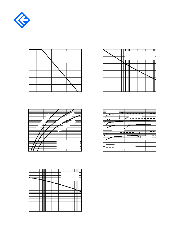
Fig. 1 - Maximum Forward Current
Derating Curve
Fig. 3 - Typical Instantaneous
Forward Characteristics
Fig. 5 - Typical Junction
Capacitance
Fig. 2 - Maximum Non-Repetitive Peak
Forward Surge Current
Fig. 4 - Typical Reverse Leakage
Characteristics
Average Forward Rectified Current (A)
Instantaneous Forward Current (A)
Junction Capacitance (pF)
Instantaneous Reverse Leakage
Current (
A
)
Peak Forward Surge Current (A)
Ambient Temperature (
-
C)
Instantaneous Forward Voltage (V)
Reverse Voltage (V)
Percent of Rated Peak Reverse Voltage (%)
Number of Cycles at 60 Hz
Resistive or
Inductive Load
0.375" (9.5mm)
Lead Length
T
A
= 55
-
C
8.3ms single half sine-wave
(JEDEC Method)
E
S
1A
M
- E
S
1D
M
ES
1K
M
&
ES
1M
M
T
J
= 25
-
C
Pulse Width = 300
e s
1% Duty Cycle
T
J
= 25
-
C
f = 1 MHz
Vsig = 50mVp-p
T
J
= 125
-
C
T
J
= 25
-
C
T
J
= 100
-
C
T
J
= 125
-
C
ES1AM - ES1GM
ES1JM - ES1MM
Ratings and
Characteristic Curves
(T
A
= 25
-
C unless otherwise noted)
ES
1G
M
&
ES
1J
M