75 A
300 A
450 A
2
sec
≠ 55 to + 150 ∞C
≠ 55 to + 150 ∞C
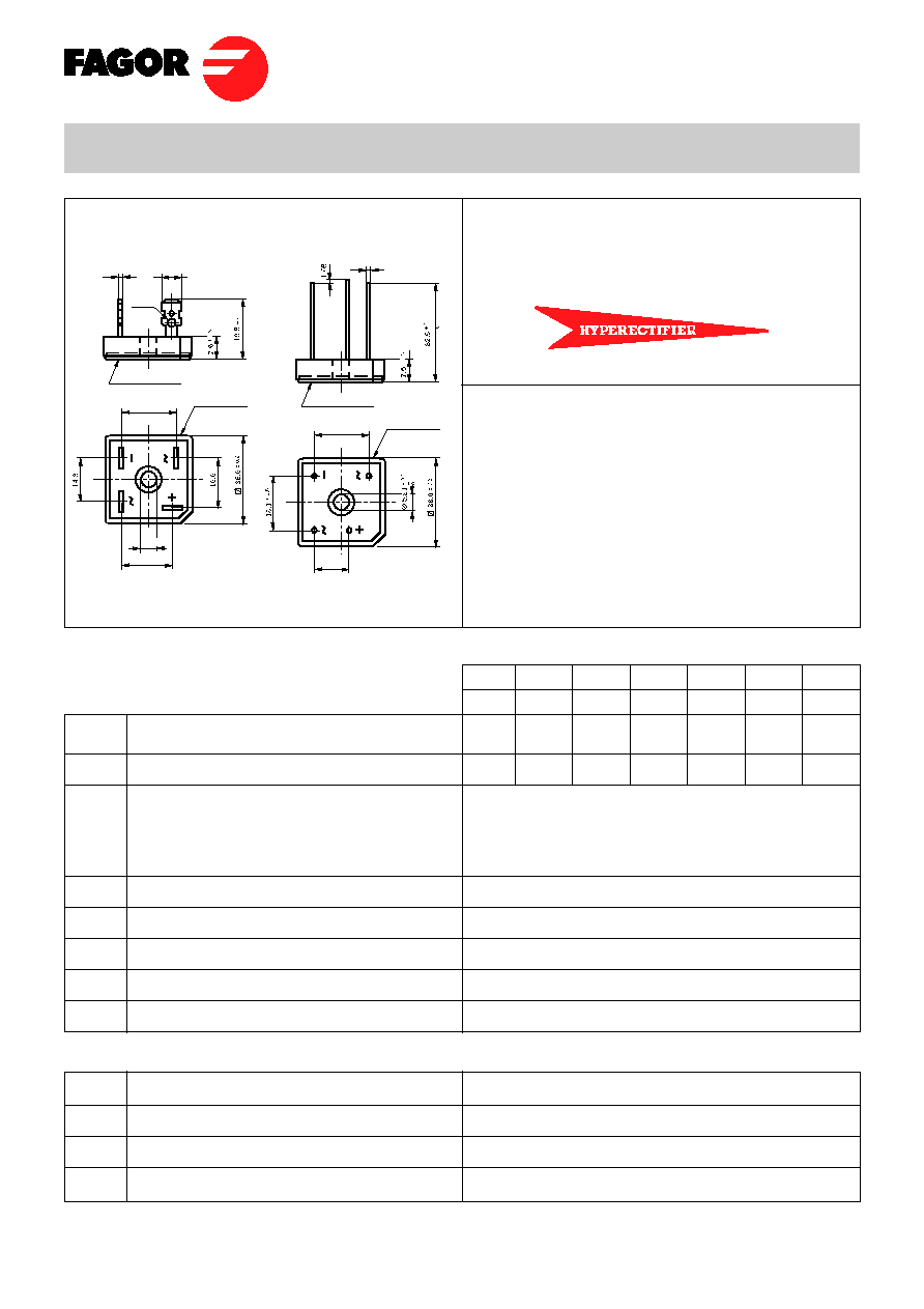
FB2500
FB2500L
50
20
FB2500........ FB2510
FB2500L........ FB2510L
Dimensions in mm.
Maximum Ratings, according to IEC publication No. 134
Max. peak working voltage (V)
Recommended input voltage (V)
Max. forward current R-load: At T case = 55
o
C
Max. forward current R-load:
At T case = 90
o
C
With Al Square Chassis (200 cm
2
x 3 mm.)
Tamb = 45
o
C
Recurrent peak forward current
10 ms. peak forward current
I
2
t value for fusing (t = 10 ms)
Operating temperature range
Storage temperature range
V
RWM
V
RMS
I
F(AV)
25 A
17 A
10 A
I
FRM
I
FSM
I
2
t
T
j
T
stg
Electrical Characteristics at Tamb = 25 ∞C
V
F
I
R
R
thj-c
Max. forward voltage drop per element at I
F
= 12.5 A
Max. reverse current per element at V
RRM
d.c.
Typical thermal resistance junction to case
Isolation voltage from case to leads
1.1 V
5 µ A
1.4
o
C/W
2500 Vac
FB2501
FB2501L
100
40
FB2502
FB2502L
200
80
FB2504
FB2504L
400
125
FB2506
FB2506L
600
250
FB2508
FB2508L
800
380
FB2510
FB2510L
1000
500
∑ Glass Passivated Junction
∑ UL recognized under component
index file number E130180
∑ Terminals: FASTON
∑ Terminals: WIRE LEADS
Lead and polarity identifications
High surge current capability
25 Amp. Glass Passivated Bridge Rectifier
Voltage
50 to 1000 V
Current
25 A
Metal heat sink
ÿ 1
± 0.05
Epoxy case
18.1
± 0.5
11.4
± 0.5
Metal heat sink
0.8
± 0.05
6.35
± 0.05
ÿ 2.5
ÿ 5.21
+ 0.1
≠
0
Epoxy case
18.1
16.6
∑ Max. Mounting Torque: 25 Kg
x
cm
Æ
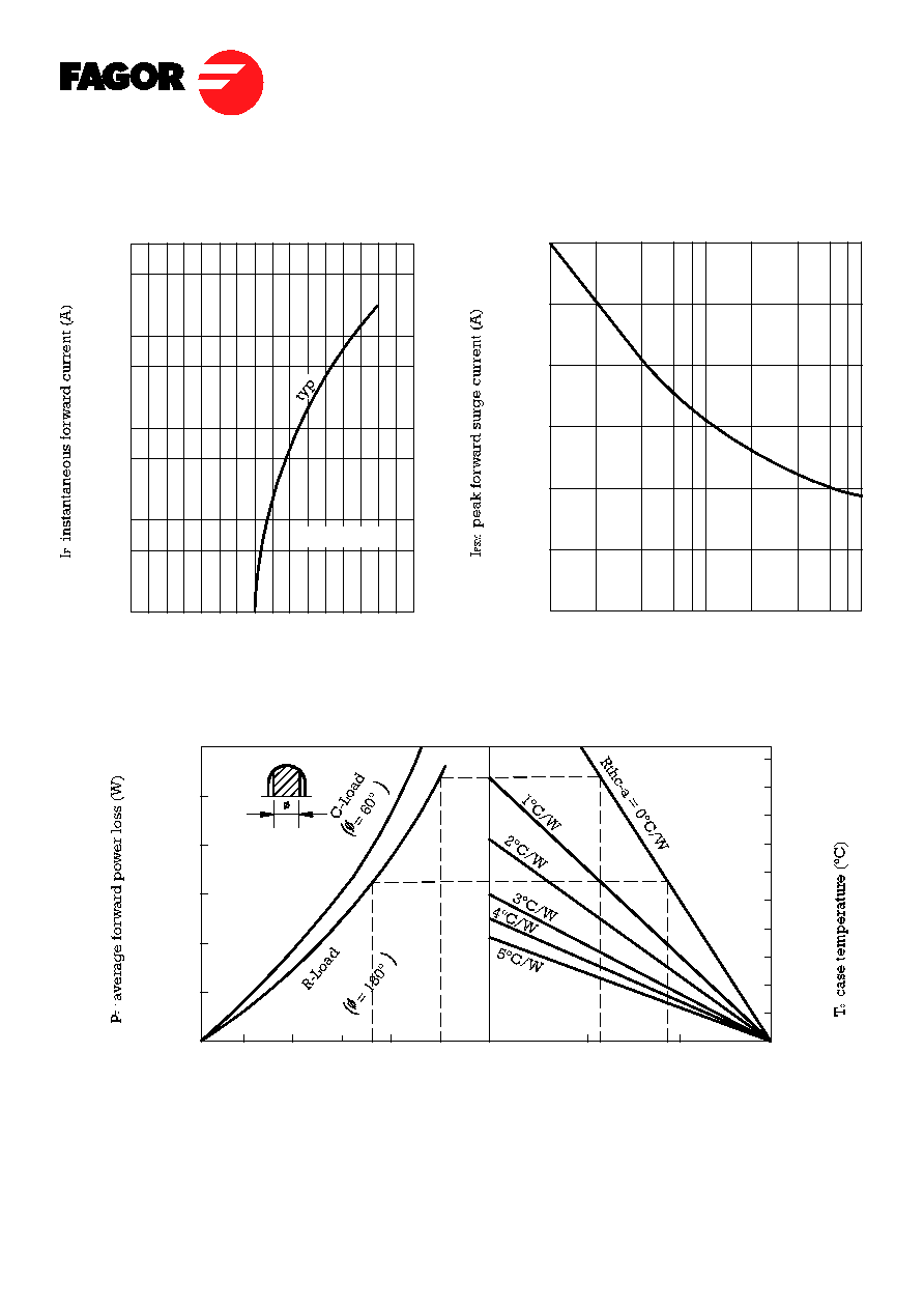
V
F '
instantaneous forward voltage (V)
Characteristic Curves
Tj = 25∫C
0
0.4
0.8
1.2
1.6
FB25
Tamb, ambient temperature (∞C)
I
F (AV)¥
average forward current (A)
60
50
40
30
20
10
50
60
70
80
90
100
110
120
130
140
0
5
10
15
20
25
0
50
100
150
1000
500
100
50
10
5
1
0.5
0.1
Number of cycles at 50Hz
1
2
4
6
10
20
40
60 100
300
250
200
150
100
50
0
TYPICAL FORWARD CHARACTERISTIC
MAXIMUM NON-REPETITIVE
PEAK FORWARD SURGE CURRENT