
To Order, please specify Pan Overseas Part No. as the following example
Temperature Characteristics Code
CH (NPO)
SL
B (Y5P)
E (Z5U)
F (Z5V)
X (X7R)
RY (Y5R)
FY (Y5V)
T.C.(PPM/) or
Cap. Change %
0
± 60PPM
+ 350
- 12000PPM
± 10%
+ 22%
-56%
+ 22%
- 82%
± 15%
± 15%
+ 22%
- 82%
Rated Voltage
B
T
U
A
C
M
M2
M3
Voltage
16V
25V
50V
100V
500V
1000V
2000V
3000V
Part Diameter(mm)
Code
Diameter
Code
Diameter
Code
Diameter
Code
Diameter
5
5mm 8
8mm
A
11mm
D
14mm
6
6mm 9
9mm
B
12mm
E
15mm
7
7mm 0
10mm
C
13mm
F
16mm
Capacitance Code
Code
Capacitance (pF)
Code
Capacitance (pF)
010
1
102
1000
1R5
1.5
222
2200
100
10
472
4700
101
100
103
10000
Lead Configuration Code-Bulk & Taping Package
Configuration and Dimension
Bulk
Lead Code
Taping
Lead Code
Kinked / Straight
Lead Space (F)
Lead Length (L)
Remarks
2
Straight 5.0mm 5
±1mm
5
Straight
2.5mm
25 mm Min.
6
G or L
Straight
5.0mm
25mm Min.
G = Ammo, L = Reel
7
Straight 6.4mm
25mm
Min.
8
Inside Kinked
5.0mm
5
±1mm
9
H or R
Inside Kinked
5.0mm
25 mm Min.
H = Ammo, R = Reel
A
Straight 10.0mm 5
±1mm
B
Inside Kinked
10.0mm
5
±1mm
C
Straight
10.0mm
25 mm Min.
High temperature soldering type.
Epoxy coating material is used on 2KV & 3KV parts only.
Tolerance Code
Code
Tolerance
Code
Tolerance
C
± 0.25pF
K
± 10%
D
± 0.50pF
M
± 20%
J
± 5%
Z
+ 80-20%
CERAMIC DISC CAPACITOR
Pan Overseas
HOW TO ORDER
≠ PART NUMBER EXPLANATION
CH
U
5
100
J
H
H
A
13

FEATURES
Capacitance has linear temperature coefficient
Capacitance high stability
Low lost at wide range of frequency
GENERAL SPECIFICATION
Capacitance Range
1pF to 820pF
Capacitance Tolerance
±0.25pF, ±0.5pF, ±5%, ±10%
Operating Temperature Range
-25 ~ 85
Rated Working Voltage Rating
50, 500 VDC
Q Factor @ 1MHz, 1±0.2Vrms, 25
C30 pF...........Q1,000, C30 pF.........Q400+20*C
Insulation Resistance (IR) @ 25 10,000
M Minimum
Dielectric Strength
3 times the rated WVDC
Testing Parameters
1MHz
±20%, 1.0Vrms±0.2Vrms
CAPACITANCE CHART
Capacitance
Dim.(mm) Max.
Temp.
Char.
Part
Dia.
Rated
Voltage
Range (pF)
Tol.
D
T
F
5
0.5 - 47
5.5
6 51
-
75
6.5
7 82
-
100
7.5
8 120
-
150
8.5
10 180
-
270
10.5
12
U
(50V)
300 - 390
12.5
3.5
5
0.5 - 36
5.5
6
39 - 56
6.5
8 68
-
100
8.5
CH
0
±60
ppm/
10
C
(500V)
120 - 150
C, D
( 10pF)
J, K
(>=10pF)
10.5
4.0
5.00
When Ordering, please use the Pan Overseas part number as indicated on page no. 13.
Capacitance
Dim.(mm) Max.
Temp.
Char.
Part
Dia.
Rated
Voltage
Range (pF)
Tol.
D
T
F
5 10
-
120
5.5
6 150
-
220
6.5
7 240
-
330
7.5
8 360
-
470
8.5
10
U
(50V)
500 - 820
10.5
3.5
5 10
-
82
5.5
6 100
-
150
6.5
8 180
-
220
8.5
SL
+ 350
-1200
ppm/
10
C
(500V)
240 - 390
J, K
10.5
4.0
5.00
CERAMIC DISC CAPACITOR
Pan Overseas
CLASS I TEMPERATURE COMPENSATION TYPE
14
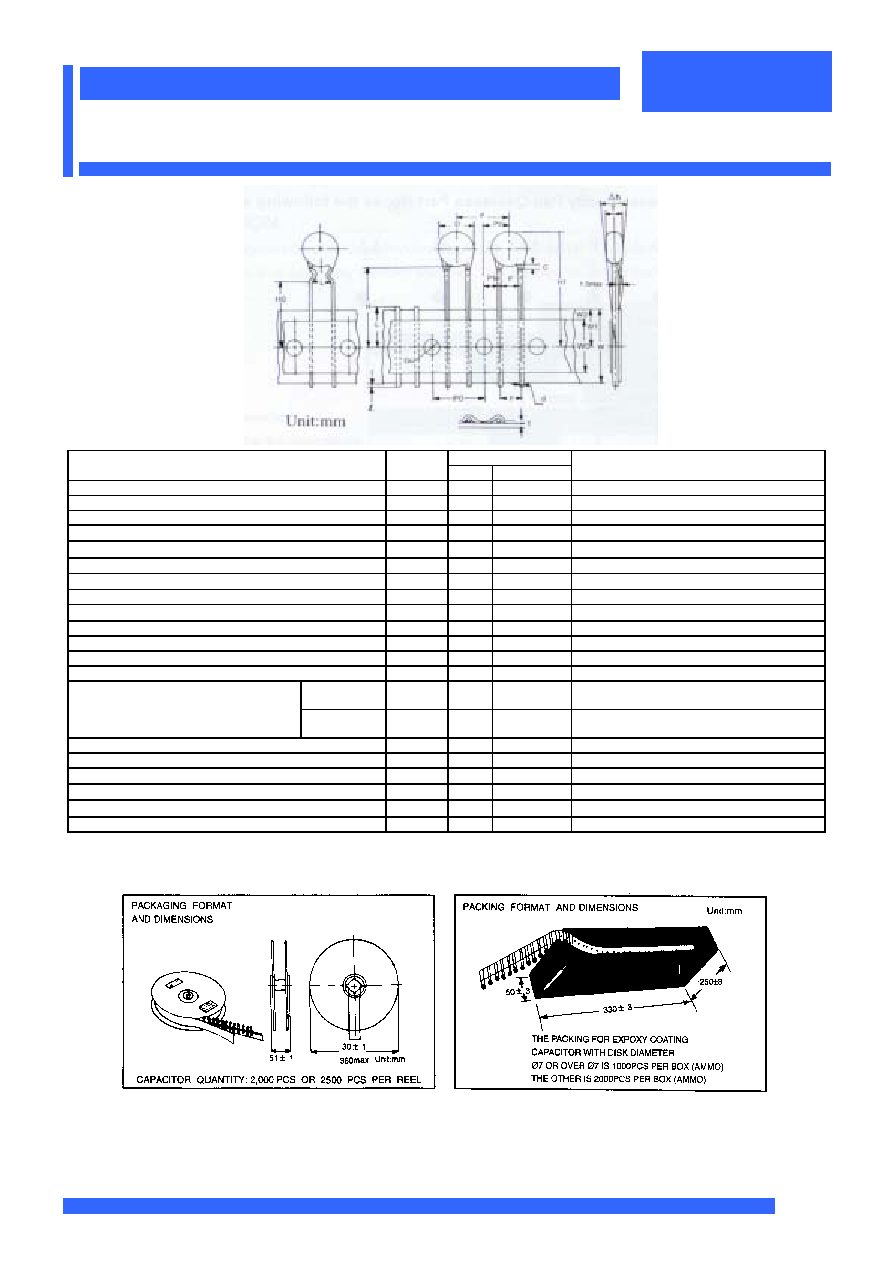
Specification
Item Symbol
Value Tolerance
Remarks
Body diameter
D
11.0
Max
Body thickness
T
3.5
Max
Lead-wire diameter
d
0.6
+0.06-0.05
Pitch of component
P
12.7
±1.0
Feed hole pitch
P
0
12.7
±0.3
Cumulative pitch error 1.0 mm/20 pitch
Feed hole center to lead
P
1
3.85
±0.7
To be measured at bottom of clinch
Hole center to component center
P
2
6.35
±1.3
Lead-to lead distance
F
5.0
+0.8 -0.2
Component alignment, F-R.
h
0
±2.0
Tape width
W
18.0
+1.0 -0.5
Hold-down tape width
W
0
11.0 Min
Hole position
W
1
9.0
+0.75
-0.5
Hold-down tape position
W
2
3.0 Max
For Straight
Lead Type
H 20.0
+1.0
-0.5
Height of component form tape center
For Kinked
Lead Type
H
0
16.0
±0.5
Component height
H
1
32.25 Max
Lead-wire protrusion
l
2.0
Max
Feed hole diameter
D
0
4.0
±0.3
Total tape thickness
t
0.7
±0.2
Length of snipped lead
L
11.0
Max
Ground paper 0.5
±0.1 mm
Coating rundown on leads
C
1.5
Max
These radial taped ceramic disc capacitors are designed especially for automatic insertion, and is only available
For those parts have diameter of 11.0mm or smaller.
CERAMIC DISC CAPACITOR
Pan Overseas
TAPING SPECIFICATION AND DIMENSION
19