357 Beloit Street, P.O. Box 457, Burlington, WI 53105-0457 U.S.A. Phone 262/763-3591 FAX 262/763-2881
Email:
nelsales@nelfc.com
www.nelfc.com
CMOS (TTL Compatible)
HS-460 Series
Description
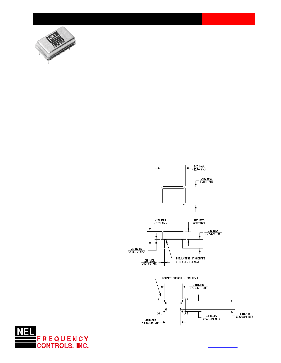
The HS-460 Series of quartz crystal oscillators are resistance welded in an all metal package, offering RFI
shielding, and are designed to survive standard wave soldering operations without damage. Insulated
standoffs to enhance board cleaning are standard.
Features
∑ Wide frequency range≠0.5MHz to 30.0MHz
∑ User specified tolerance available
∑ Will withstand vapor phase temperatures of 253įC
for 4 minutes maximum
∑ Space-saving alternative to discrete component
oscillators
∑ High shock resistance, to 3000g
∑ All metal, resistance weld, hermetically sealed
package
∑ Low Jitter
∑ High Q Crystal actively tuned oscillator circuit
∑ Power supply decoupling internal
∑ No internal PLL avoids cascading PLL problems
∑ High frequencies due to proprietary design
∑ Gold plated leads - Solder dipped leads available
upon request
∑ CMOS and TTL output levels
∑ RoHS Compliant, Lead Free Construction
(unless solder dipped leads are supplied)
Electrical Connection
Pin Connection
1 N.C.
7 Grd & Case
8 Output
14 V
DD
CRYSTAL CLOCK OSCILLATORS
Data Sheet 0021E
Rev. F
357 Beloit Street, P.O. Box 457, Burlington, WI 53105-0457 U.S.A. Phone 262/763-3591 FAX 262/763-2881
Email:
nelsales@nelfc.com
www.nelfc.com
HS-460 Series
Continued
CMOS (TTL Compatible)
Operating Conditions and Output Characteristics
Electrical Characteristics
Parameter
Symbol
Conditions
Min
Typical
Max
Frequency
-----
-----
0.5MHz
-----
30.0MHz
Duty Cycle -----
@ V
DD
/2
45/55% -----
55/45%
Logic 0
V
OL
@ 600ĶA -----
-----
0.2V
@ 16mA
-----
-----
0.4V
Logic 1
V
OH
@ 600ĶA
V
DD
-0.2V
-----
-----
@ 16mA
V
DD
-0.4V
-----
-----
Rise & Fall Time
tr,tf
10-90%V
O
-----
-----
3 ns
Jitter, RMS
(2)
-----
-----
-----
-----
8 psec
Frequency Stability
(1)
dF/F
Overall conditions including:
-100ppm
-----
+100ppm
voltage, calibration, temp.,
10 yr aging, shock, vibration
General Characteristics
Parameter
Symbol
Conditions
Min
Typical
Max
Supply Voltage
V
DD
-----
4.5V
5.0V
5.5V
Supply Current
I
DD
No Load
0.0 mA
-----
30 mA
Output current
I
O
-----
0.0 mA -----
Ī16.0 mA
Operating temperature
T
A
-----
0įC -----
70įC
Storage temperature
T
S
----- -55įC -----
125įC
Power Dissipation
P
D
-----
-----
-----
210 mW
Lead temperature
T
L
Soldering, 10 sec. ----- -----
300įC
Load
-----
-----
-----
-----
15pf
Start-up Time
t
s
<20MHz
-----
-----
2 ms
20MHz or greater
-----
-----
10 ms
Environmental and Mechanical Characteristics
Mechanical Shock
Per MIL-STD-202, Method 213, Condition E
Thermal Shock
Per MIL-STD-833, Method 1011, Condition A
Vibration
0.060" double amplitude 10 Hz to 55 Hz, 35g's 55Hz to 2000 Hz
Soldering Condition
300įC for 10 seconds
Hermetic Seal
Leak rate less than 1 x 10
-8
atm.cc/sec of helium
Footnotes:
1) Standard frequency stability (Ī20,Ī25,Ī50ppm & others available)
2) Jitter performance is frequency dependent. Please contact factory for full characterization.
RMS jitter bandwidth of 12kHz to 20MHz.
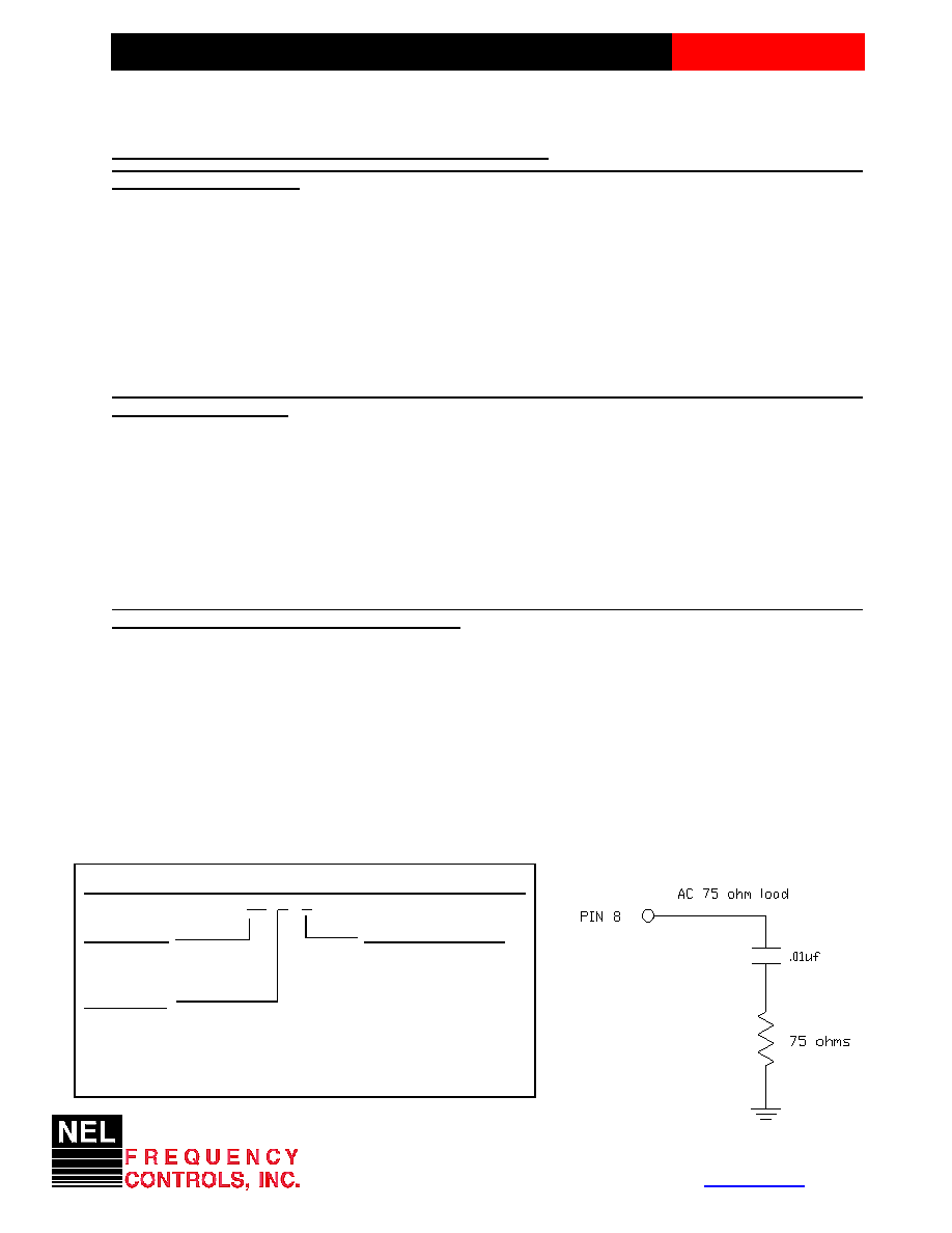
Test Load:
Rev. F
CRYSTAL CLOCK OSCILLATORS
HS - A46X - FREQ
Package Code
Tolerance/Performance
HS Leaded 4 pin (14 pin)
0 Ī100ppm 0-70įC
SM Leaded 4 pin (14 pin) SMD
1 Ī50ppm 0-70įC
Gull Wing
7 Ī25ppm 0-70įC
Input Voltage
9 Customer Specific
Code Specification
A Ī20ppm 0-70įC
A 3.3V
B Ī50ppm -40 to +85įC
5V
C Ī100ppm -40 to +85įC
Creating a Part Number
Data Sheet 0021E