
MIL-PRF-19500/420H
19 April 2004
SUPERSEDING
MIL-PRF-19500/420G
30 December 2002
PERFORMANCE SPECIFICATION SHEET
* SEMICONDUCTOR DEVICE, DIODE, SILICON, POWER, RECTIFIER,
TYPES 1N5550 THROUGH 1N5554, 1N5550US THROUGH 1N5554US,
JAN, JANTX, JANTXV, JANS, JANHCA, JANHCB, JANHCC, JANHCD,
JANHCE, JANKCA, JANKCD, AND JANKCE
This specification is approved for use by all Departments
and Agencies of the Department of Defense.
*
The requirements for acquiring the product described herein shall consist of
this specification sheet and MIL-PRF-19500.
1. SCOPE
* 1.1 Scope. This specification covers the performance requirements for silicon, general purpose, semiconductor
diodes. Four levels of product assurance are provided for each encapsulated device type as specified in
MIL-PRF-19500. Two levels of product assurance are provided for each unencapsulated device type.
1.2 Physical dimensions. See figure 1 (similar to DO-41) for 1N5550 through 1N5554, figure 2 for 1N5550US
through 1N5554US, and figures 3, 4, 5, 6, and 7 for JANHC and JANKC die.
1.3 Maximum ratings. Unless otherwise specified, T
C
= +25
�
C and ratings apply to all case outlines.
Col. 1
Col. 2
Col. 3
Col. 4
Col. 5
Col. 6
Col. 7
Col. 8
Type
V
(BR)
V
RWM
and
V
(BR)min
I
O1
T
L
= +55
�
C;
L = .375 inch
(1) (2) (3)
I
FSM
I
O
= 2 A dc
t
p
= 1/120 s
T
A
= +55
�
C
T
J
I
O2
T
A
=
+55
�
C
(2) (4)
T
STG
1N5550, 1N5550US
1N5551, 1N5551US
1N5552, 1N5552US
1N5553, 1N5553US
1N5554, 1N5554US
200
400
600
800
1,000
V dc
200
400
600
800
1,000
A dc
5
5
5
5
5
A(pk)
100
100
100
100
100
�
C
-65 to +200
-65 to +200
-65 to +200
-65 to +200
-65 to +200
A dc
3
3
3
3
3
�
C
-65 to +175
-65 to +175
-65 to +175
-65 to +175
-65 to +175
(1) Derate linearly at 41.6 mA/
�
C above T
L
= +55
�
C at L = .375 inch (9.53 mm).
(2) An
I
O
of up to 6 A dc is allowable provided that appropriate heat sinking or forced air cooling maintains the
maximum junction temperature at or below +200
�
C as proven by the junction temperature rise test (see 6.5).
Barometric pressure reduced:
1N5550, 1N5551, 1N5552 - 8 mmHg (100,000 feet).
1N5553, 1N5554 - 33 mmHg (70,000 feet).
(3) Does not apply to surface mount devices.
(4) Derate linearly at 25 mA/
�
C above T
A
= +55
�
C.
AMSC N/A
FSC 5961
INCH-POUND
The documentation and process conversion
measures necessary to comply with this revision
shall be completed by 19 July 2004.
* Comments, suggestions, or questions on this document should be addressed to Defense Supply Center,
Columbus, ATTN: DSCC-VAC, P.O. Box 3990, Columbus, OH 43216-5000, or emailed to
Semiconduction@dscc.dla.mil
. Since contact information can change, you may want to verify the currency of
this address information using the ASSIST Online database at
http://www.dodssp.daps.mil
.

MIL-PRF-19500/420H
2
1.4 Primary electrical characteristics. Unless otherwise specified, T
A
= +25
�
C.
Type
V
f
at I
f
= 9.0 A(pk)
1 percent duty cycle,
8.3 ms max pulse width
I
R1
I
R2
at T
A
= +100
�
C
R
JL
R
JEC
1N5550, 1N5550US
1N5551, 1N5551US
1N5552, 1N5552US
1N5553, 1N5553US
1N5554, 1N5554US
Min V(pk)
0.6
0.6
0.6
0.6
0.6
Max V(pk)
1.2
1.2
1.2
1.3
1.3
�
A dc (max) at V
R
(V dc)
1.0 200
1.0 400
1.0 600
1.0 800
1.0 1,000
�
A dc (max) at V
R
(V dc)
75 200
75 400
75 600
75 800
75 1,000
See (1)
(1) R
JL
22
�
C/W for L = .375 inch (9.52 mm).
R
JEC
11
�
C/W for L = 0 (US version).
2. APPLICABLE DOCUMENTS
* 2.1 General. The documents listed in this section are specified in sections 3, 4, or 5 of this specification. This
section does not include documents cited in other sections of this specification or recommended for additional
information or as examples. While every effort has been made to ensure the completeness of this list, document
users are cautioned that they must meet all specified requirements of documents cited in sections 3, 4, or 5 of this
specification, whether or not they are listed.
2.2 Government documents.
* 2.2.1 Specifications, standards, and handbooks. The following specifications, standards, and handbooks form a
part of this document to the extent specified herein. Unless otherwise specified, the issues of these documents are
those cited in the solicitation or contract.
* DEPARTMENT OF DEFENSE SPECIFICATIONS
MIL-PRF-19500 - Semiconductor
Devices, General Specification for.
* DEPARTMENT OF DEFENSE STANDARDS
MIL-STD-750
-
Test Methods for Semiconductor Devices.
* (Copies of these documents are available online at
http://assist.daps.dla.mil/quicksearch/
or
www.dodssp.dap.mil
or from the Standardization Document Order Desk, 700 Robbins Avenue, Building 4D, Philadelphia, PA
19111-5094.)
2.3 Order of precedence. In the event of a conflict between the text of this document and the references cited
herein, the text of this document takes precedence. Nothing in this document, however, supersedes applicable laws
and regulations unless a specific exemption has been obtained.

MIL-PRF-19500/420H
3
Ltr
Dimensions
Notes
Inches
Millimeters
Min
Max
Min
Max
BL
.130
.300
3.30
7.62
3
BD
.115
.180
2.92
4.57
3, 4
LD
.037
.042
0.94
1.07
LL
.900
1.300
22.86
33.02
LU
.050
1.27
NOTES:
1.
Dimensions are in inches.
2.
Millimeters are given for general information only.
3.
Dimensions BL and BD include all components of the diode periphery
except the sections of leads over which the diameter is controlled.
4.
Dimension BD shall be measured at the largest diameter.
5.
Dimension LU shall include the sections of the lead over
which the diameter is uncontrolled. This uncontrolled area
is defined as the zone between the edge of the diode body
and extending .050 inch (1.27 mm) onto the leads.
6.
In accordance with ASME Y14.5M, diameters are
equivalent to
x symbology.
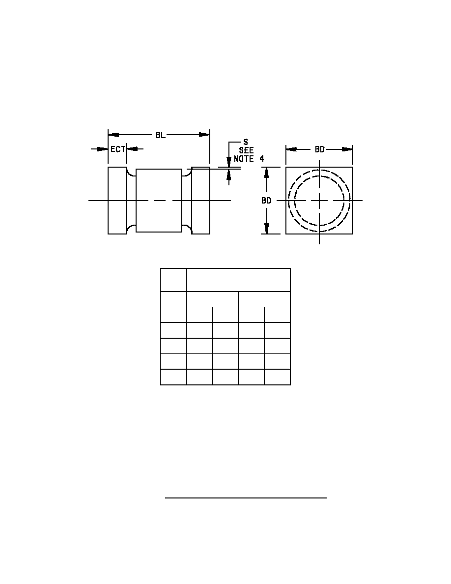
* FIGURE 1. Physical dimensions of diode 1N5550 through 1N5554, (similar to DO-41).
MIL-PRF-19500/420H
4
Ltr
Dimensions
Inches
Millimeters
Min
Max
Min
Max
BL
.200
.275
5.08
6.99
BD
.137
.180
3.48
4.57
ECT
.019
.034
0.48
0.86
S
.003
0.08
NOTES:
1. Dimensions are in inches.
2. Millimeters are given for general information only.
3. Dimensions are pre-solder dip.
4. Minimum clearance of glass body to mounting surface on all orientations.
5. In accordance with ASME Y14.5M, diameters are equivalent to
x
symbology.
* FIGURE 2. Physical dimensions of 1N5550US through 1N5554US.
MIL-PRF-19500/420H
5
Ltr
Dimensions
Inches
Millimeters
Min
Max
Min
Max
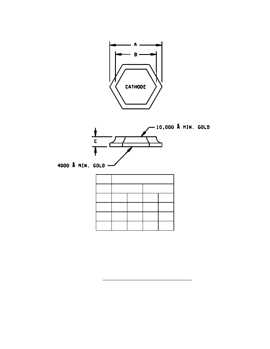
A
.085
.091
2.16
2.31
B
.072
.078
1.83
1.98
C
.008
.014
0.20
0.36
NOTES:
1. Dimensions are in inches.
2. Millimeters are given for general information only.
3. The physical characteristics are:
Top (cathode) Au Thickness = 10,000� minimum,
Back (anode) Au Thickness = 4,000� minimum.
4. In accordance with ASME Y14.5M, diameters are equivalent to
x symbology.
* FIGURE 3. JANHCA and JANKCA (A-version) die dimensions.
MIL-PRF-19500/420H
6
Ltr
Dimensions
Inches
Millimeters
Min
Max
Min
Max
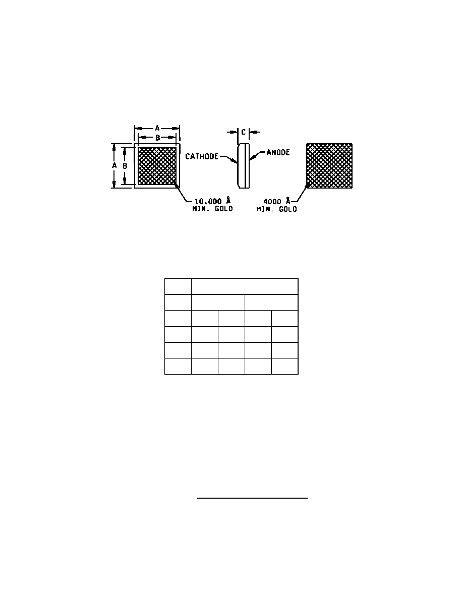
A
.088
.092
2.24
2.34
B
.070
.077
1.78
1.96
C
.007
.035
0.18
0.89
NOTES:
1. Dimensions are in inches.
2. Millimeters are given for general information only.
3. The physical characteristics are
Top (cathode) Au Thickness = 10,000� minimum,
Back (anode) Au Thickness = 4,000� minimum.
4. In accordance with ASME Y14.5M, diameters are equivalent to
x symbology.
* FIGURE 4. JANHCB (B-version) die dimensions.

MIL-PRF-19500/420H
7
Ltr
Dimensions
Inches
Millimeters
Min
Max
Min
Max
A
.060
.065
1.52
1.65
B
.052
.058
1.32
1.47
C
.008
.014
0.20
0.36
NOTES:
1. Dimensions are in inches.
2. Millimeters are given for general information only.
3. The physical characteristics are
Top (cathode) Au Thickness = 10,000� minimum,
Back (anode) Au Thickness = 4,000� minimum.
4. In accordance with ASME Y14.5M, diameters are equivalent to
x
symbology.
* FIGURE 5. JANHCC (C-version) die dimensions.

MIL-PRF-19500/420H
8
Ltr Inches Millimeters
Min
Max
Min
Max
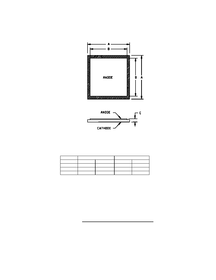
A .081 .087 2.05
2.20
B .055 .061 1.40
1.55
C .007 .012 0.18
0.30
NOTES:
1. Dimensions are in inches.
2. Millimeters are given for general information only.
3. The physical characteristics are
Top (anode) Al Thickness = 60,000� minimum.
Back (cathode) Au Thickness = 2,500� minimum,
4. In accordance with ASME Y14.5M, diameters are equivalent to
x symbology.
* FIGURE 6. JANHCD and JANKCD (D-version) die dimensions.
MIL-PRF-19500/420H
9
Ltr Inches Millimeters
Min
Max
Min
Max
A .081 .087 2.05
2.20
B .055 .061 1.40
1.55
C .007 .012 0.18
0.30
NOTES:
1. Dimensions are in inches.
2. Millimeters are given for general information only.
3. The physical characteristics are
Top (anode) Al Thickness = 60,000� minimum.
Back (cathode) Al/Ti/Ni/Ag Thickness = 2,500� minimum,
4. In accordance with ASME Y14.5M, diameters are equivalent to
x symbology.
* FIGURE 7. JANHCE and JANKCE (E-version) die dimensions.

MIL-PRF-19500/420H
10
3. REQUIREMENTS
3.1 General. The individual item requirements shall be as specified in MIL-PRF-19500 and as modified herein.
3.2 Qualification. Devices furnished under this specification shall be products that are manufactured by a
manufacturer authorized by the qualifying activity for listing on the applicable qualified manufacturer's list (QML)
before contract award (see 4.2 and 6.3).
3.3 Abbreviations, symbols, and definitions. Abbreviations, symbols, and definitions used herein shall be as
specified in MIL-PRF-19500 and as follows:.
* EC .........................End
cap.
3.4 Interface and physical dimensions. The interface and physical dimensions shall be as specified in
MIL-PRF-19500 and on figure 1 (similar to DO-41) for 1N5550 through 1N5554, figure 2 for 1N5550US through
1N5554US, and figures 3, 4, 5, 6, and 7 (JANHC and JANKC).
3.4.1 Lead finish. Unless otherwise specified, lead or end cap finish shall be solderable in accordance with
MIL-PRF-19500, MIL-STD-750, and herein. When solder alloy is used for finish the maximum lead temperature is
limited to 175
�
C maximum. Where a choice of finish is desired, it shall be specified in the acquisition document (see
6.2).
3.4.2 Diode construction. These devices shall be constructed utilizing non-cavity double plug construction with
high temperature metallurgical bonding between both sides of the silicon die and terminal pins. Metallurgical bond
shall be in accordance with the requirements of category I in MIL-PRF-19500. US version devices shall be
structurally identical to the non-surface mount devices except for lead terminations.
3.5 Marking. Marking shall be in accordance with MIL-PRF-19500.
3.5.1 Marking of US version. For US version only, all marking may be omitted from the device except for the
cathode marking. All marking which is omitted from the body of the device shall appear on the label of the initial
container.
3.5.2 Polarity. The polarity shall be indicated with a contrasting color band to denote the cathode end. Alternately
for surface mount (US) devices, a minimum of three evenly spaced contrasting color dots around the periphery of the
cathode end may be used. No color coding will be permitted.
3.6 Electrical performance characteristics. Unless otherwise specified herein, the electrical performance
characteristics are as specified in 1.3, 1.4, and table I herein.
3.7 Electrical test requirements. The electrical test requirements shall be the subgroups specified in table I
herein.
3.8 Workmanship. Semiconductor devices shall be processed in such a manner as to be uniform in quality and
shall be free from other defects that will affect life, serviceability, or appearance.
4. VERIFICATION
4.1 Classification of inspections. The inspection requirements specified herein are classified as follows:
a. Qualification inspection (see 4.2).
b. Screening (see 4.3).
c. Conformance inspection (see 4.4).

MIL-PRF-19500/420H
11
4.2 Qualification inspection. Qualification inspection shall be in accordance with MIL-PRF-19500 and as specified
herein.
4.2.1 Group E qualification. Group E qualification shall be performed herein for qualification or requalification
only. In case qualification was awarded to a prior revision of the specification sheet that did not request the
performance of table II tests, the tests specified in table II herein shall be performed on the first inspection lot to this
revision to maintain qualification.
4.2.2 JANHC and JANKC die. Qualification shall be in accordance with appendix G of MIL-PRF-19500 and as
specified herein.
* 4.3 Screening (JANS, , JANTXV and JANTX levels only). Screening shall be in accordance with table IV of
MIL-PRF-19500 (appendix E), and as specified herein. Specified electrical measurements shall be made in
accordance with table I herein. Devices that exceed the limits of table I herein shall not be acceptable.
Screen (see
table IV of
MIL-PRF-19500)
JANS level
JANTXV and JANTX level
1a
1b
Required
Required
Not required
Required (JANTXV only)
2
Optional
Not required
3a
3b
(1) 3c
Required
Not applicable
Thermal impedance (see 4.3.1 and 4.4.1)
Required
Not applicable
Thermal impedance (see 4.3.1 and 4.4.1)
4
Not applicable
Not applicable
5
Not applicable
Not applicable
6
Not applicable
Not applicable
7a
7b
Not applicable
Optional
Not applicable
Optional
8 Required
Not
required
9
V
F1
and I
R1
Not applicable
10
Method 1038 of
MIL-STD-750, condition A
Method 1038 of
MIL-STD-750, condition A
11
V
F1
and I
R1
;
V
f1
�
0.1 V dc
I
R1
�
250 nA dc or 100 percent of initial
value whichever is greater.
V
F1
and I
R1
12
Required, see 4.3.2
Required, see 4.3.2
(2) 13
Subgroups 2 and 3 of table I herein;
I
R1
100 percent of initial reading or 250
nA dc, whichever is greater.
V
F1
�.1 V dc change from initial value.
Scope display evaluation (see 4.5.3)
Subgroup 2 of table I herein;
I
R1
100 percent of initial reading or 250 nA
dc, whichever is greater.
V
F1
�.1 V dc change from initial value.
Scope display evaluation (see 4.5.3)
14a
(3) 14b
Not applicable
Required
Not applicable
Required
15 Required
Not
required
16 Required
Not
required
(1) Thermal impedance shall be performed any time after sealing provided temperature cycling is performed in
accordance with MIL-PRF-19500, screen 3 prior to this thermal test.
(2) Z
JX is not required in screen 13, if already previously performed.
(3)
For clear glass diodes, the hermetic seal (gross leak) may be performed at any time after
temperature cycling.

MIL-PRF-19500/420H
12
* 4.3.1 Thermal impedance Z
JX
measurements for screening. The Z
JX
measurements shall be performed in
accordance with method 3101 of MIL-STD-750. The maximum screen limit shall be developed by the supplier using
statistical methods and it shall not exceed the table I, subgroup 2 herein. See 4.4.1 for test conditions.
4.3.1.1 Thermal impedance (Z
JX
measurements) for initial qualification or requalification. The Z
JX
measurements shall be performed in accordance with method 3101 of MIL-STD-750 (read and record date Z
JX
).
Z
JX
shall be supplied on one lot (500 pieces minimum and a thermal response curve shall be submitted.) Twenty-
two of these samples shall be serialized and provided to the qualifying activity for correlation prior to shipment of
parts. Measurements conditions shall be in accordance with 4.4.1.
* 4.3.2 Power burn-in conditions. Power burn-in conditions are as follows (see 4.5.2, 4.5.2.1) adjust I
O
to achieve
the required TJ.
4.3.3 Screening (JANHC and JANKC). Screening of die shall be in accordance with appendix G of
MIL-PRF-19500. As a minimum, die shall be 100-percent probed to ensure compliance with table I, subgroup 2.
Burn-in duration for the JANKC level follows JANS requirements; the JANHC follows JANTX requirements.
* 4.4 Conformance inspection. Conformance inspection shall be in accordance with MIL-PRF-19500 and as
specified herein.
4.4.1 Group A inspection. Group A inspection shall be conducted in accordance with MIL-PRF-19500 and table I
herein. The following test conditions shall be used for Z
JX
, table I: Z
JX
1.5
�
C/W.
a.
I
M
............................. 1 mA to 10 mA.
b.
I
H
.............................. 5 A minimum.
c.
t
H
.............................. 10 ms.
d.
t
MD
........................... 100
�
s maximum.
e.
t
SW
........................... 5
�
s maximum.

MIL-PRF-19500/420H
13
* 4.4.2 Group B inspection. Group B inspection shall be conducted in accordance with the tests and conditions
specified for subgroup testing in table VIa (JANS) and table VIb (JAN, JANTX and JANTXV) of MIL-PRF-19500.
Electrical measurements (end-points) requirements shall be in accordance with the applicable inspections of table I,
subgroup 2 herein. For delta requirements see table III herein.
* 4.4.2.1 Group B inspection, table VIa (JANS) of MIL-PRF-19500. For B5, if a failure occurs, resubmission shall
be at the test conditions of the original sample.
Subgroup
Method Condition
B3 1056
0
�
C to +100
�
C, 25 cycles.
B3 1051
-55
�
C to +175
�
C, 100 cycles.
B3 4066
I
FSM
= rated I
FSM
(see col. 5 of 1.3); 10 surges of 8.3 ms each at 1 minute
intervals, superimposed on I
O
= 0, V
RWM
= 0.
B4
1037
I
O
= I
O2
rated minimum (see col. 4 of 1.3)
V
R
= rated V
RWM
(see col. 3 of 1.3 and 4.5.5); 2,000 cycles.
B5
1027
I
O
= I
O2
rated minimum (see col. 4 of 1.3); apply V
R
= rated V
RWM
(see col. 3 of 1.3
and 4.5.2) adjust I
O
to achieve T
J
minimum; f = 50-60 Hz.
Option 1: T
A
= + 30
�
C max. ; T
J
= 225
�
C minimum; t = 216 hours; n = 45 c = 0.
or
Option 2: T
A
= + 100
�
C max. ; T
J
= 275
�
C minimum; t = 96 hours, n = 22,
c = 0.
* B6
3101
R
JL
(maximum)
22
�
C/W; L = .375 inch (9.53 mm).
or
For surface mount devices (US version), R
JEC
11
�
C/W.
4081
B7
Peak reverse power, see 4.5.5. P
RM
1,000 W. Test shall be performed on
each sublot; sampling plan n = 10, c = 0, electrical end-points, see table I,
subgroup 2 herein.
* 4.4.2.2 Group B inspection, table VIb (JAN, , JANTX and JANTXV of MIL-PRF-19500).
Subgroup
Method Condition
B2 1056
0
�
C to +100
�
C, 10 cycles.
* B2 1051
-55
�
C to +175
�
C, 25 cycles.
B3 1027
T
J
= 150
�
C minimum (see 4.5.2.1). Adjust I
O
to achieve the required T
J
; apply
V
R
= rated
V
RWM
(see col. 3 of 1.3), f = 50-60 Hz (see 4.5.2).
B5
Not applicable .
4.4.3 Group C inspection. Group C inspection shall be conducted in accordance with the tests and conditions
specified for subgroup testing in table VII of MIL-PRF-19500. Electrical measurements (end-points) shall be in
accordance with table I, subgroup 2 herein. See table III herein for delta limits when applicable.

MIL-PRF-19500/420H
14
* 4.4.3.1 Group C inspection, table VII of MIL-PRF-19500.
Subgroup
Method Condition
C2 1056
0
�
C to +100
�
C, 10 cycles.
C2 1051
-55
�
C to +175
�
C, 25 cycles.
C2
2036
Tension: Test condition A; weight = 5 pounds; t = 30 seconds.
Lead fatigue: Test condition E; weight 2 pounds.
NOTE: Both tension and lead fatigue are not applicable for US devices.
* C5 3101
See
4.5.5.
or
4081
C6 1027
T
J
= 150
�
C minimum (see 4.5.2.1). I
O
= I
O2
= 3 A dc minimum; adjust I
O
to
achieve the required T
J
; apply V
R
= rated
V
RWM
(see col. 3 of 1.3), f = 50-60 Hz
(see 4.5.2.1).
* 4.4.4 Group E inspection. Group E inspection shall be conducted in accordance with the conditions specified for
subgroup testing in appendix E, table IX of MIL-PRF-19500 and as specified herein. Electrical measurements (end-
points) shall be in accordance with table I, subgroup 2 herein. See table III for delta limits when applicable.
4.5 Methods of inspection. Methods of inspection shall be as specified in appropriate tables and as follows.
4.5.1 Pulse measurements. Conditions for pulse measurement shall be as specified in section 4 of MIL-STD-750.
4.5.2 Burn-in and life tests. These tests shall be conducted with a half-sine waveform of the specified peak
voltage impressed across the diode in the reverse direction followed by a half-sine waveform of the specified
average rectified current. The forward conduction angle of the rectified current shall be neither greater than 180
degrees, nor less than 150 degrees.
* 4.5.2.1 Free air burn-in. Deliberate heat sinking, baffles to create an oven, forced air-cooling or heating is
prohibited unless otherwise approved by the qualifying activity. The use of a current limiting or ballast resistor is
permitted provided that each DUT still sees the full P
t
(minimum) and that the minimum applied voltage, where
applicable, is maintained through out the burn-in period. T
J
= 135
�
C minimum for screening and T
J
= 150
�
C for 4.4.2
and 4.4.3 life tests. Use method 3100 of MIL-STD-750 to measure T
J
.
4.5.3 Scope display evaluation. Scope display evaluation shall be sharp and stable in accordance with method
4023 of MIL-STD-750. Scope display may be performed on ATE (automatic test equipment) for screening only, with
the approval of the qualifying activity. Scope display in table I, subgroup 4 shall be performed on a scope. The
reverse current (I
BR
) over the knee shall be 500
�
A peak.

MIL-PRF-19500/420H
15
4.5.4 Thermal resistance. Thermal resistance measurements shall be conducted in accordance with test
method 3101 or 4081 of MIL-STD-750. Read and record data in accordance with group E herein and shall be
included in the qualification report. Forced moving air or draft shall not be permitted across the devices during
test. The maximum limit under these test condition shall be R
JL
22
�
C/W for L = .375 (9.53 mm);
R
JEC
11
�
C/W for L= 0 (US version). The following conditions shall apply:
a. I
H
............................. 2 A minimum.
b. t
H
............................. Thermal
equilibrium.
c. I
M
............................. 1.0 mA to 10 mA.
d. t
MD
............................. 100
�
s maximum.
The device shall be allowed to reach equilibrium at current I
H
before the measurement shall be made (t
H
25 sec).
LS = Lead spacing = .375 inch (9.53 mm) minimum for leaded devices and LS = 0 minimum for unleaded devices as
defined (see figure 8):
FIGURE 8. Mounting arrangement.
4.5.5 Peak reverse power test. A 20 microsecond half-sine waveform of current shall be used and peak reverse
power shall be determined by the product of peak reverse voltage and peak reverse current. A 20 microsecond
square waveform may also be used with the approval of the qualifying activity (see figure 9).
MIL-PRF-19500/420H
16
* TABLE I. Group A inspection.
Inspection 1/
MIL-STD-750
Symbol
Limits
Unit
Method
Conditions
Min
Max
Subgroup 1
Visual and mechanical
inspection
2071
Subgroup 2
Thermal impedance
3101
See 4.3.1 and 4.4.1.
Z
JX
1.5
�
C/W
Forward voltage
1N5550, 1N5550US
1N5551, 1N5551US
1N5552, 1N5552US
1N5553, 1N5553US
1N5554, 1N5554US
4011
I
F
= 9.0 A(pk); duty cycle
2
percent (pulsed see 4.5.1);
t
p
8.3 ms
V
F1
0.6
0.6
0.6
0.6
0.6
1.2
1.2
1.2
1.3
1.3
V(pk)
V(pk)
V(pk)
V(pk)
V(pk)
Forward voltage
4011
I
F
= 1.5 A dc
V
F1
0.5
1.0
V dc
Reverse current
leakage
1N5550, 1N5550US
1N5551, 1N5551US
1N5552, 1N5552US
1N5553, 1N5553US
1N5554, 1N5554US
4016
DC method
V
R
= 200 V dc
V
R
= 400 V dc
V
R
= 600 V dc
V
R
= 800 V dc
V
R
= 1,000 V dc
I
R1
1.0
1.0
1.0
1.0
1.0
�
A dc
�
A dc
�
A dc
�
A dc
�
A dc
Breakdown voltage
(diodes)
1N5550, 1N5550US
1N5551, 1N5551US
1N5552, 1N5552US
1N5553, 1N5553US
1N5554, 1N5554US
4021
I
R
= 50
�
A dc
I
R
= 50
�
A dc
I
R
= 50
�
A dc
I
R
= 50
�
A dc
I
R
= 50
�
A dc
V
BR1
200
400
600
800
1,000
V dc
V dc
V dc
V dc
V dc
See footnote at end of table.
MIL-PRF-19500/420H
17
TABLE I. Group A inspection - Continued.
Inspection 1/
MIL-STD-750
Symbol
Limits
Unit
Method
Conditions
Min
Max
Subgroup 3
High temperature
operation:
T
A
= +100
�
C
Reverse current
leakage
DC method
I
R2
Reverse current
leakage
1N5550, 1N5550US
1N5551, 1N5551US
1N5552, 1N5552US
1N5553, 1N5553US
1N5554, 1N5554US
4016
DC method
V
R
= 200 V dc
V
R
= 400 V dc
V
R
= 600 V dc
V
R
= 800 V dc
V
R
= 1,000 V dc
75
75
75
75
75
�
A dc
�
A dc
�
A dc
�
A dc
�
A dc
Forward voltage
1N5550, 1N5550US
1N5551, 1N5551US
1N5552, 1N5552US
1N5553, 1N5553US
1N5554, 1N5554US
4011
I
F
= 9.0 A(pk); duty cycle
2
percent (pulsed see 4.5.1); t
p
8.3 ms
V
F2
1.2
1.2
1.2
1.3
1.3
V(pk)
V(pk)
V(pk)
V(pk)
V(pk)
Low temperature
operation:
T
A
= -55
�
C
Forward voltage
4011
I
F
= 9.0 A(pk); duty cycle
2
percent (pulsed); t
p
8.3 ms
V
F3
1.5
V(pk)
Forward voltage
4011
I
F
= 1.5 A dc
V
F4
0.5
1.2
V dc
Breakdown voltage
(diodes)
1N5550, 1N5550US
1N5551, 1N5551US
1N5552, 1N5552US
1N5553, 1N5553US
1N5554, 1N5554US
4021
I
R
= 50
�
A dc
I
R
= 50
�
A dc
I
R
= 50
�
A dc
I
R
= 50
�
A dc
I
R
= 50
�
A dc
V
BR2
200
400
600
800
1,000
V dc
V dc
V dc
V dc
V dc
Subgroup 4
Reverse recovery time
4031
Condition B1
t
rr
2.0
�
s
Scope display evaluation
4023
See 4.5.3, n = 116, c = 0
See footnote at end of table.

MIL-PRF-19500/420H
18
TABLE I. Group A inspection - Continued.
Inspection 1/
MIL-STD-750
Symbol
Limits
Unit
Method
Conditions
Min
Max
Subgroups 5
Not applicable
Subgroup 6
Forward surge
4066
I
FSM
= rated (see col. 6 of 1.3);
10 surges of 8.3 ms each at 1
minute intervals, superimposed
on I
O
= 0, V
RSM
= 0
Electrical measurement
See table I, subgroup 2.
Subgroup 7
Not applicable
1/ For sampling plan, see MIL-PRF-19500.

MIL-PRF-19500/420H
19
* TABLE II. Group E inspection (all quality levels) for qualification and requalification only.
Inspection
MIL-STD-750
Sampling
plan
Method
Conditions
Subgroup 1
Thermal shock
1056
20 cycles, condition D except low temperature shall be
achieved using liquid nitrogen (-195
�
C). Perform a visual for
cracked glass.
45 devices
c = 0
Temperature cycling
Electrical measurements
1051
500 cycles, condition C, -65
�
C to +175
�
C.
See table I, subgroup 2 herein.
Subgroup 2
22 devices
c = 0
Steady state dc blocking life
1048
1,000 hours, condition A; V
R
= V
RWM
Electrical measurements
See table I, subgroup 2 and table III herein.
* Subgroup 3
3 devices
c = 0
DPA (Decap analysis)
2101
Cross section and scribe and break.
Separate samples shall be used for each test.
* Subgroup 4
Thermal impedance
curves
Each supplier shall submit their (typical) maximum design
thermal impedance curves. In addition, optional test
conditions and Z
JX
limit shall be provided to the qualifying
activity in the qualification report.
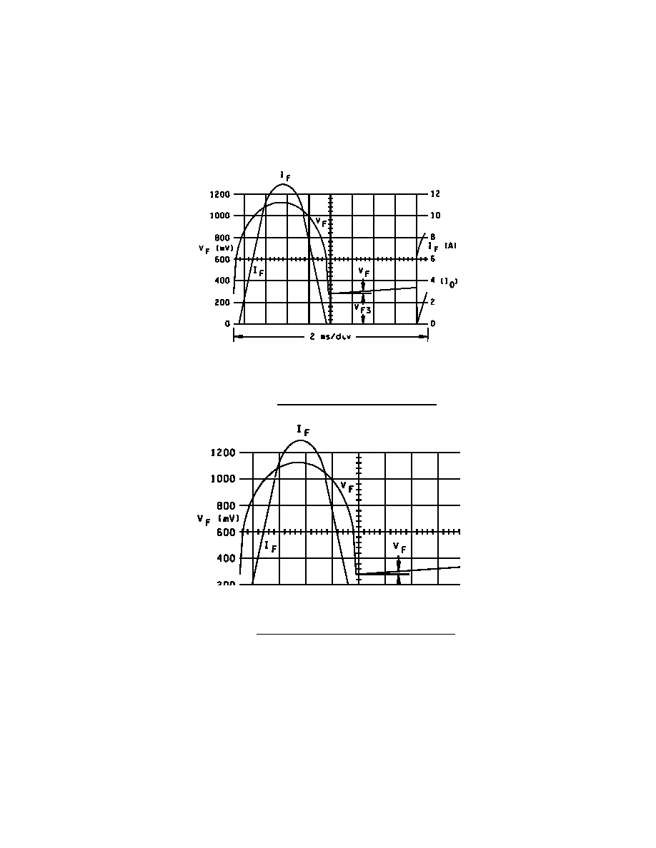
Junction temperature
rise (see 4.5.2.1)
See figures 10, 11, and 12;
T
J
120
�
C; L = .375 inch;
T
L
= 55
�
C; I
O
= 5 A dc.
Subgroup 5
22 devices
c = 0
Barometric pressure,
reduced (altitude
operation)
1001
Pressure (see 1.3); t = 1 min. DC method;
V
R
= V
RWM
(see 1.3); I
R1
= 1.0
�
A dc maximum
Electrical measurement
See table I, subgroup 2 and table III herein.
* Subgroup 6
ESD
1020
n = 3, c = 0
See footnotes at end of table.

MIL-PRF-19500/420H
20
* TABLE II. Group E inspection (all quality levels) for qualification and requalification only - Continued.
Inspection
MIL-STD-750
Sampling
plan
Method
Conditions
* Subgroup 8
Peak reverse power
See 4.5.5 herein. Peak reverse power (P
RM
)= shall be
characterized by the supplier and this data shall be available
to the Government. Test shall be performed on each sublot.
Electrical measurement
During the P
RM
test, the voltage (V
BR
) shall be monitored to
verify it has not collapsed. Any collapse in V
BR
during or
after the P
RM
test or rise in leakage current (I
R
) after the test
that exceeds I
R1
in table I shall be considered a failure to that
level of applied P
RM
. Progressively higher levels of P
RM
shall
be applied until failure occurs on all devices within the
chosen sample size to characterize each sublot.
Subgroup 9 1/
n = 45
Resistance to glass
cracking
1057
Step stress to destruction by increasing cycles or up to a
maximum of 25 cycles.
* Subgroup 10
22 devices
c = 0
Forward surge
4066
I
FSM
= 80 A(pk); 10 surges of 8.3 ms each at 1 minute
intervals, superimposed on I
O
= 2 A dc; V
RWM
= rated V
RWM
(see col. 3 of 1.3). T
A
= +100
�
C.
Electrical measurement
See table I, subgroup 2 and table III herein.
1/ The sample size for this step stress requirement shall be determined by the supplier. A statistically significant
sample size is required.
MIL-PRF-19500/420H
21
* TABLE III. Delta requirements. 1/ 2/ 3/ 4/ 5/
Step
Inspection
MIL-STD-750
Symbol
Limits
Unit
Method
Conditions
Min
Max
1.
Reverse current
leaking change
4016
DC method
I
R1
4/
�100 percent of
initial value or
�250 nA dc,
whichever is
greater.
2.
Forward voltage
change
4011
I
F
= 1.5 A dc;
pulsed (see 4.5.1)
V
F1
4/
�50 mV dc
maximum
change from
previous
measured value.
1/ The electrical measurements for table VIa (JANS) of MIL-PRF-19500 are as follows:
a. Subgroup 3, see table III herein, step 2.
b. Subgroup 4, see table III herein, step 2.
c.
Subgroup 5, see table III herein, steps 1 and 2.
2/ The electrical measurements for table VIb (JAN, , JANTX and JANTXV) of MIL-PRF-19500 are as follows:
a. Subgroup 3, see table III herein, step 1.
b. Subgroup 6, see table III herein, step 1.
3/ The electrical measurements for table VII of MIL-PRF-19500 are as follows:
a. Subgroup 2, see table III herein, step 1 (JANS).
b. Subgroup 6, see table III herein, step 1 and 2 (JANS), step 1 (JAN, JANTX, JANTXV and).
4/ Devices which exceed the table I limits for this test shall not be accepted.
5/ The electrical measurements for table IX of MIL-PRF-19500 are as follows:
a. Subgroup 2 and 10, see table III herein, step 1 and 2.

MIL-PRF-19500/420H
22
NOTES: *
L = 13T H22 on 1 inch (25.4 mm) diameter form (air core).
C ~ 1 to 10
�
fd to give 20
�
s pulse width.
V - Adjustable to 200 volts for power desired in DUT.
D1 - 3 kV; 600 Ma (1N3647 or equivalent).
D2, D3 - 600 V; 3A (1N5552 or equivalent).
* Values not stated are determined at the time of test.
FIGURE 9. Typical peak reverse power measurement circuit and waveforms.
MIL-PRF-19500/420H
23
NOTE: Blocking diode shall have a forward current rating
6 A dc.
FIGURE 10. Junction temperature rise test circuit.
FIGURE 11. Junction temperature test oscillogram (typical).
MIL-PRF-19500/420H
24
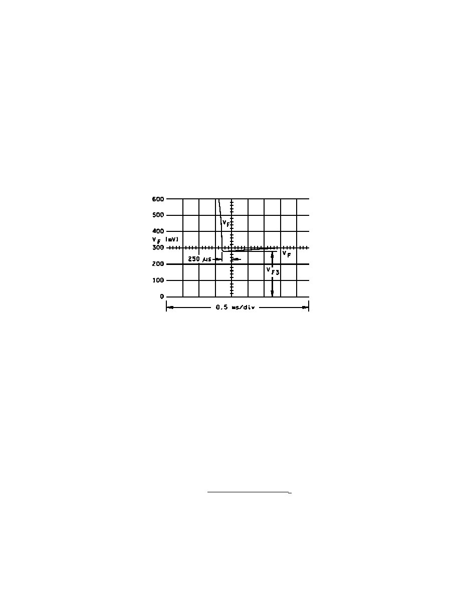
FIGURE 12. Expanded oscillogram of V
F
.

MIL-PRF-19500/420H
25
5. PACKAGING
* 5.1 Packaging. For acquisition purposes, the packaging requirements shall be as specified in the contract or
order (see 6.2). When actual packaging of materiel is to be performed by DoD or in-house contractor personnel,
these personnel need to contact the responsible packaging activity to ascertain packaging requirements. Packaging
requirements are maintained by the Inventory Control Point's packaging activities within the Military Service or
Defense Agency, or within the Military Service's system commands. Packaging data retrieval is available from the
managing Military Department's or Defense Agency's automated packaging files, CD-ROM products, or by
contacting the responsible packaging activity.
6. NOTES
(This section contains information of a general or explanatory nature that may be helpful, but is not mandatory.)
6.1 Intended use. The notes specified in MIL-PRF-19500 are applicable to this specification.
* 6.2 Acquisition requirements. Acquisition documents should specify the following:
a. Title, number, and date of this specification.
b. Packaging requirements (see 5.1).
c. Lead finish (see 3.4.1).
d. Product assurance level and type designator.
6.3 Qualification. With respect to products requiring qualification, awards will be made only for products which
are, at the time of award of contract, qualified for inclusion in Qualified Manufacturers List (QML 19500) whether or
not such products have actually been so listed by that date. The attention of the contractors is called to these
requirements, and manufacturers are urged to arrange to have the products that they propose to offer to the Federal
Government tested for qualification in order that they may be eligible to be awarded contracts or orders for the
products covered by this specification. Information pertaining to qualification of products may be obtained from
Defense Supply Center, Columbus, ATTN: DSCC/VQE, P.O. Box 3990, Columbus, OH 43216-5000 or e-mail
vqe.chief@dla.mil.
6.4 Supersession information. Devices covered by this specification supersede the manufacturers' and
users' Part or Identifying Number (PIN). This information in no way implies that the manufacturers' PIN's
are suitable as a substitute for the military PIN.
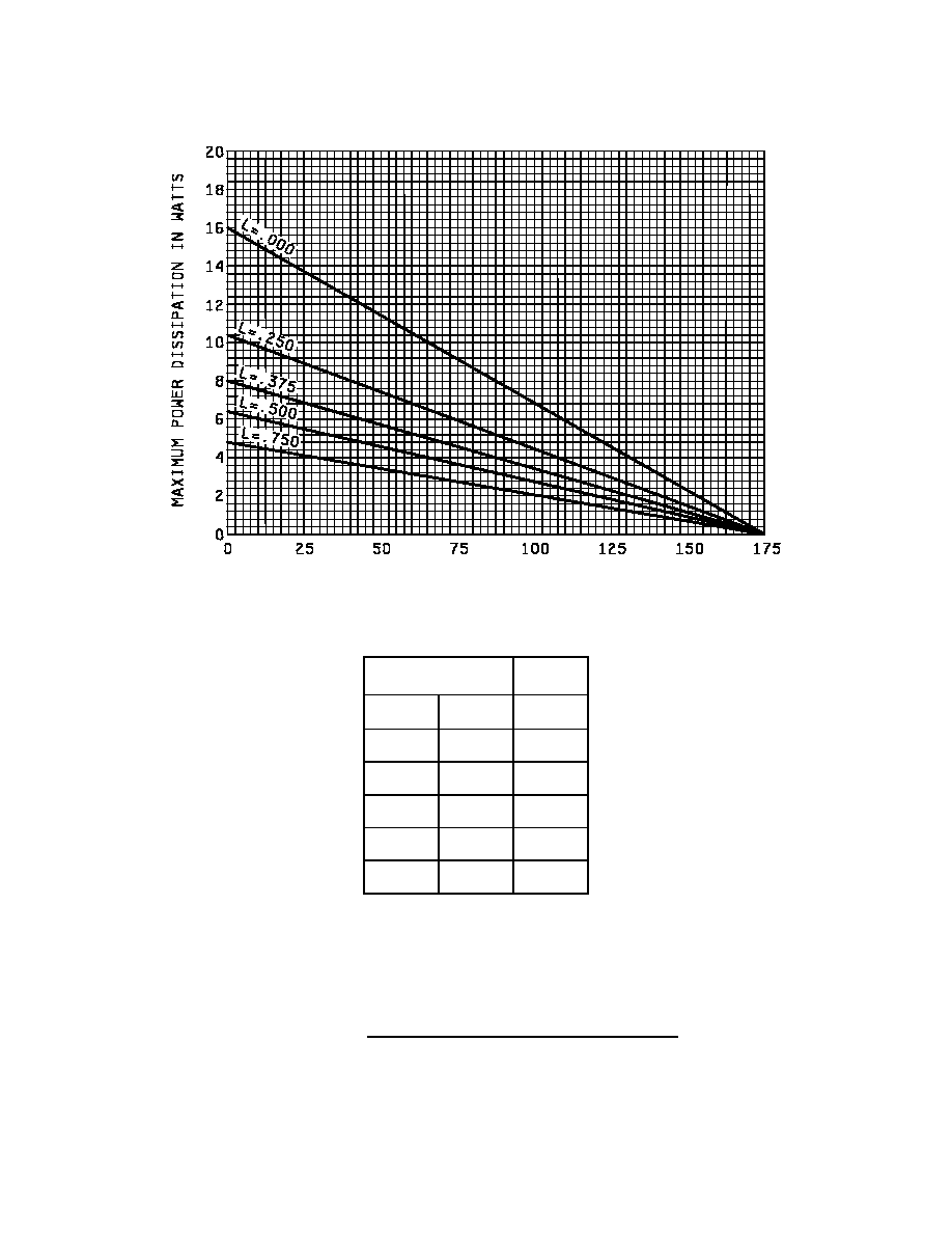
6.5 Applications data. See figure 13 for maximum power in watts as a function of lead temperature at a
distance "L" from the diode body. Device current capability with lead-dissipators or body forced-air-cooling,
may be determined from figure 14, which shows maximum average rectified current versus lead
temperature as a function of the distance L from the diode body at which lead temperature is measured.
MIL-PRF-19500/420H
26
Maximum lead temperature in
�
C (T
L
) at point "L" from body (for maximum operating junction temperature
of +175
�
C with equal two-lead conditions).
L
R
JL
Inches
mm
�
C/W
.000
0.00
11
.250
6.35
16.5
.375
9.53
22
.500
12.70
26
.750
19.05
35.5
NOTES:
1. Dimensions are in inches.
2. Millimeters are given for general information only.
3. In accordance with ASME Y14.5M, diameters are equivalent to
x
symbology.
* FIGURE 13. Maximum power in watts versus lead temperature.

MIL-PRF-19500/420H
27
NOTES
1. Dimensions are in inches.
2. Millimeters are given for general information only.
FIGURE 14. Maximum current vs lead temperature.

MIL-PRF-19500/420H
28
6.6 Suppliers of die. The qualified die suppliers with the applicable letter version (example JANHCA1N5550) will
be identified on the QML.
JANC ordering information
PIN
Manufacturer
14552 60211 13409 33178 33178
1N5550
1N5551
1N5552
1N5553
1N5554
JANHCA1N5550
JANKCA1N5550
JANHCA1N5551
JANKCA1N5551
JANHCA1N5552
JANKCA1N5552
JANHCA1N5553
JANKCA1N5553
JANHCA1N5554
JANKCA1N5554
JANHCB1N5550
JANHCB1N5551
JANHCB1N5552
JANHCB1N5553
JANHCB1N5554
JANHCC1N5550
JANHCC1N5551
JANHCC1N5552
JANHCC1N5553
JANHCC1N5554
JANHCD1N5550
JANHCD1N5551
JANHCD1N5552
JANHCD1N5553
JANHCD1N5554
JANHCE1N5550
JANHCE1N5551
JANHCE1N5552
JANHCE1N5553
JANHCE1N5554
6.7 Changes from previous issue. The margins of this specification are marked with asterisks to indicate where
changes from the previous issue were made. This was done as a convenience only and the Government assumes
no liability whatsoever for any inaccuracies in these notations. Bidders and contractors are cautioned to evaluate the
requirements of this document based on the entire content irrespective of the marginal notations and relationship to
the last previous issue.
Custodians:
Preparing activity:
Army - CR
DLA - CC
Navy - EC
Air Force - 11
DLA - CC
Review activities:
(Project 5961-2760)
Army - AR, MI, SM
Navy - AS, MC
Air Force - 19, 71, 84, 99
* NOTE: The activities listed above were interested in this document as of the date of this document. Since
organizations and responsibilities can change, you should verify the currency of the information above using the
ASSIST Online database at http:\\
www.dodssp.daps.mil
.