,
Features
Small size, light weight.
Low coil power consumption.
PC board mounting.
Suitable for household electrical appliance, automation system, electronic equipment, instrument, meter,
telecommunication facilities and remote control facilities.
Ordering Information
JRC-19F 2C 3V 0.2
1 2 3 4
1 Part number
JRC-19F
2 Contact arrangement
2A:2A
2C:2C
3 Coil rated Voltage(V)
DC:3,4.5,5,6,12,24,48,
4 Coil power consumption
0.15:0.15W
0.2:0.2W
0.36:0.36W
0.51:0.51W
Contact Data
Contact Arrangement
2A DPSTNO
f
2C DPDT(B-M)
Contact Material
Ag Ag Ni(Au clad)
Contact Rating (resistive)
2A/24VDC; 0.5A 1A/125VAC 30VDC ;
Max. Switching Power
48W 60VA
Max. Switching Voltage
24VDC 220VAC Max. Switching Current:2A
Contact Resistance or Voltage drop
50m Item 3.12 of IEC255-7
Electrical
10
5
Item 3.30 of IEC255-7
Operation
life
Mechanical
10
7
Item 3.31 of IEC255-7
Coil Parameter
Coil voltage
VDC
Dash
numbers
Rated
Max
Coil
resistance
�
10%
Pickup voltage
VDC(max)
(75%of rated
voltage )
release voltage
VDC(min)
(10% of rated
voltage)
Coil power
consumption
W
Operate
Time
ms
Release
Time
ms
003-150
3
3.9
60
2.25
0.3
004-150
4.5
5.9
135
3.15
0.45
005-150
5
6.5
166.7
3.50
0.5
006-150
6
7.8
240
4.20
0.6
012-150
12
15.6
960
8.40
1.2
024-150
24
31.2
3840
18.0
2.4
0.15
6
5
003-200
3
3.9
45
2.25
0.3
004-200
4.5
5.9
101
3.15
0.45
005-200
5
6.5
125
3.50
0.5
006-200
6
7.8
180
4.20
0.6
012-200
12
15.6
720
8.40
1.2
024-200
24
31.2
2880
18.0
2.4
0.20
6
5
003-360
3
3.9
25
2.25
0.3
004-360
4.5
5.9
56
3.15
0.45
005-360
5
6.5
70
3.50
0.5
006-360
6
7.8
100
4.20
0.6
012-360
12
15.6
400
8.40
1.2
024-360
24
31.2
1600
18.0
2.4
0.36
6
5
003-510
3
3.9
17.6
2.25
0.3
004-510
4.5
5.9
39.7
3.15
0.45
005-510
5
6.5
49
3.50
0.5
006-510
6
7.8
70.6
4.20
0.6
012-510
12
15.6
282.4
8.40
1.2
024-510
24
31.2
1129.4
18.0
2.4
048-510
48
62.4
4517.6
36.0
4.8
0.51
6
5
CAUTION
: 1.The use of any coil voltage less than the rated coil voltage will compromise the operation of the relay.
2.Pickup and release voltage are for test purposes only and are not to be used as design criteria.
47
J R C - 1 9 F ( 4 0 7 8 )
21
�
10
�
12
E158859
R2133344
www.dblectro.com
Operation condition
Insulation Resistance
1000M min (at 500VDC)
Item 7 of IEC255-5
Dielectric Strength
Between contacts
Between contact and coil
50Hz 500V
50Hz 1000V
Item 6 of IEC255-5
Item 6 of IEC255-5
Shock resistance
500m/s
2
11ms
IEC68-2-27 Test Ea
Vibration resistance
10~70Hz double amplitude 1.5mm
IEC68-2-6 Test Fc
Terminals strength
5N
IEC68-2-21 Test Ua1
Solderability
235
x
2
3
x
0.5s
IEC68-2-20 Test Ta method 1
Ambient Temperature
-30~70
Relative Humidity
85% (at 40
)
IEC68-2-3Test Ca
Mass
5g
Qualification inspection:
Perform the qualification test as specified in the table of IEC255-19-1 and minimum sample size 24.
Safety approvals
Safety approval
UL&CUR
T
�
V
Load
1A/24VDC
1A/125VAC;24DC
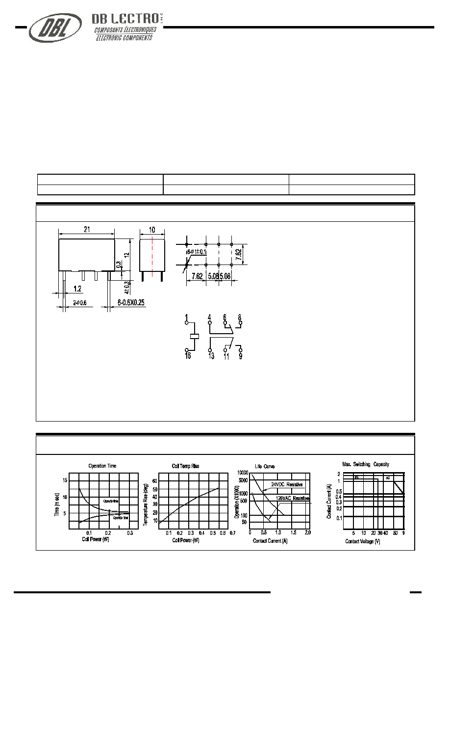
Dimensions (Unit: mm)
Reference Data
NOTES
1).Dimensions are in millimeter.
2).Inch equivalents are given for general information only.
JRC-19F(4078)
Dimensions
Wiring diagram
(Bottom views)
mm inch
0.25
0.010
0.3
0.012
0.6
0.024
1.0
0.039
1.2
0.047
4.0
0.157
5.08
0.200
7.62
0.300
10
0.394
12
0.472
21 0.827
Mounting (Bottom views)
www.dblectro.com