- 488 -
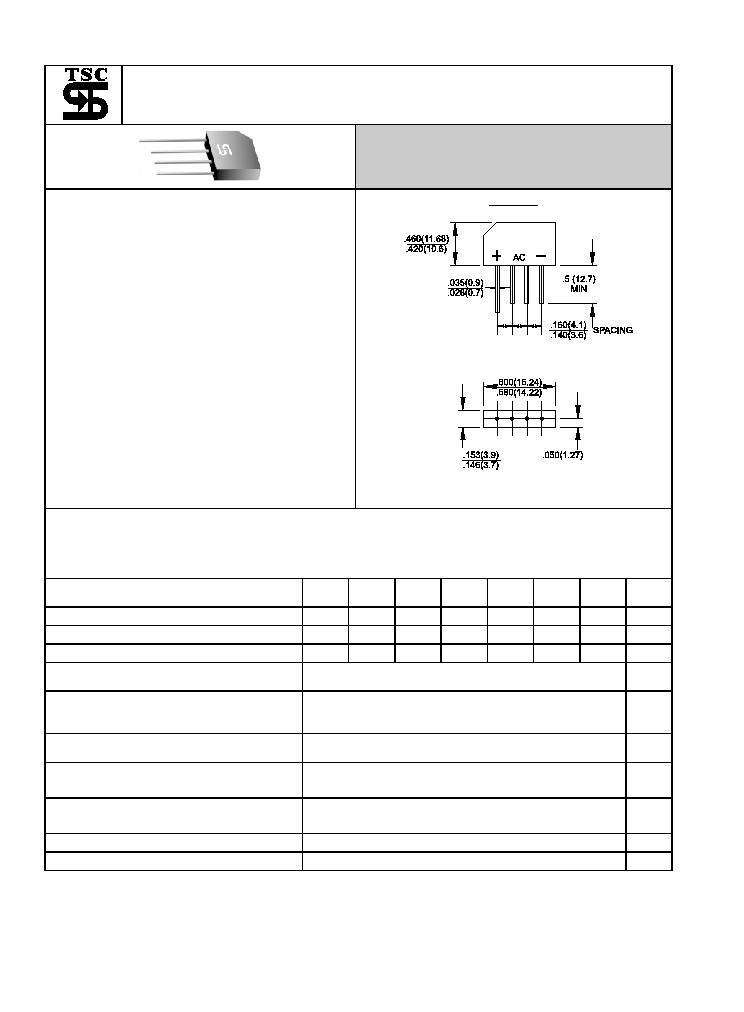
KBP301G THRU KBP307G
Single Phase 3.0 AMPS. Glass Passivated Bridge Rectifiers
Voltage Range
50 to 1000 Volts
Current
3.0 Amperes
Features
a
UL Recognized File # E-96005
a
Ideal
for
printed
circuit
board
a
Reliable low cost construction technique
results in inexpensive product
a
High temperature soldering guaranteed:
250�C
/ 10 seconds at 5 lbs. ( 2.3 Kg )
tension
a
Small
size,
simple
installation
Leads solderable per MIL-STD-202,
Method 208
KBP
Dimensions in inches and (millimeters)
Maximum Ratings and Electrical Characteristics
Rating at 25�C
ambient temperature unless otherwise specified.
Single phase, half wave, 60 Hz, resistive or inductive load.
For capacitive load, derate current by 20%
Type Number
KBP
301G
KBP
302G
KBP
303G
KBP
304G
KBP
305G
KBP
306G
KBP
307G
Units
Maximum Recurrent Peak Reverse Voltage
50
100
200
400
600
800
1000
V
Maximum RMS Voltage
35
70
140
280
420
560
700
V
Maximum DC Blocking Voltage
50
100
200
400
600
800
1000
V
Maximum Average Forward Rectified Current
@T
A
= 50�C
3.0
A
Peak Forward Surge Current, 8.3 ms Single
Half Sine-wave Superimposed on Rated Load
(JEDEC method )
80
A
Maximum Instantaneous Forward Voltage
@ 3.14A
1.1
V
Maximum DC Reverse Current @ T
A
=25�C
at Rated DC Blocking Voltage @ T
A
=125�C
10
500
uA
uA
Typical Thermal Resistance (Note 1) R
�
JA
Typical Thermal Resistance (Note 1)
R
�
JL
30.0
11
�C/w
Operating Temperature Range T
J
-55 to +150
�C
Storage Temperature Range T
STG
-55 to +150
�C
Note 1. Thermal Resistance from Junction to Ambient and from Junction to Lead Mounted on PCB
Note 1.
With 0.47 x 0.47" (12 x 12mm) Copper Pads.
- 489-
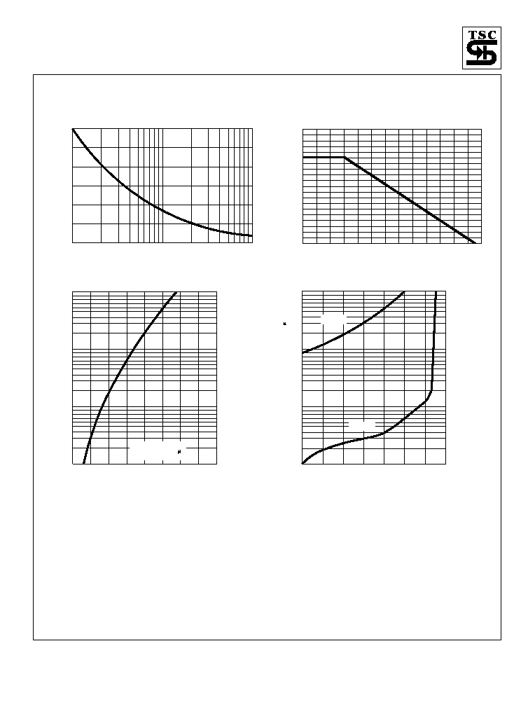
RATINGS AND CHARACTERISTIC CURVES (KBP301G THRU KBP307G)
FIG.4- TYPICAL REVERSE CHARACTERISTICS
PER BRIDGE ELEMENT
INST
ANT
ANEOUS
REVERSE
CURRENT
.(
A
)
0
20
40
60
80
100
120
140
0.1
1
10
100
PERCENT OF RATED PEAK REVERSE VOLTAGE. (%)
TJ=125 C
0
TJ=25 C
0
FIG.1- MAXIMUM NON-REPETITIVE FORWARD
SURGE CURRENT PER BRIDGE ELEMENT
PEAK
FOR
W
ARD
SURGE
CURRENT
.
(A)
10
2
4
6
1
40
60
20
100
30
20
40
50
70
80
60
NUMBER OF CYCLES AT 60Hz
FIG.2- MAXIMUM FORWARD CURRENT DERATING
CURVE
A
VERAGE
FOR
W
ARD
CURRENT
.
(A)
20
40
60
80
100
120
140 150
0
4.0
3.0
2.0
1.0
AMBIENT TEMPERATURE. ( C)
o
FIG.3- TYPICAL INSTANTANEOUS FORWARD
CHARACTERISTICS PER BRIDGE ELEMENT
INST
ANT
ANEOUS
FOR
W
ARD
CURRENT
.
(A)
.6
.7
.9
.8
1.0
1.3
1.1
1.2
1.4
.01
0.1
1.0
10.0
INSTANTANEOUS FORWARD VOLTAGE. (V)
Tj=25 C
PULSE WIDTH-300 S
1% DUTY CYCLE
0