 | –≠–ª–µ–∫—Ç—Ä–æ–Ω–Ω—ã–π –∫–æ–º–ø–æ–Ω–µ–Ω—Ç: L1481T-5 | –°–∫–∞—á–∞—Ç—å:  PDF PDF  ZIP ZIP |

L1481T-5
TO-220
1
Low Power-Loss
Voltage Regulators
NIKO-SEM
JUL-15-2002
FEATURES
Low power-loss(Dropout voltage:Max.0.5
V@ IO=1A)
Line-up for 5V and 9V output type
Compact resin package(TO-220 package)
High-precision output voltage type
(Output voltage precision: ±3.0%)
Built-in ON/OFF control function
Built-in overcurrent protection, overheat
protection, ASO protection circuit
Lead forming type is also available.
APPLICATIONS
Power supplies for varies electronic
equipment such as AV, OA equipment
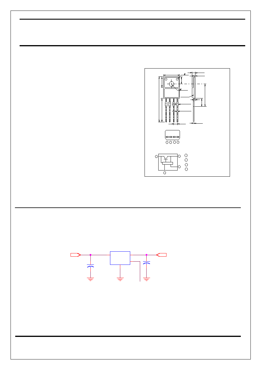
( ) : T y p i c a l d i m e n s i o n s
O N / O F F c o n t r o l t e r m i n a l ( V c )
D C i n p u t ( V i n )
D C o u t p u t ( V o )
3 - ( 2 . 5 )
S p e c i f i c I C
I n t e r n a l c o n n e c t i o n d i a g r a m
3
1
1
1
4
2
G N D
4
3
2
2
3
4
X X X X X X X X
L 1 4 8 1 T - X
1
4
.
1
M
I
N
.
2
9
.
1
M
A
X
.
±
7
.
6
0
.
2
0 . 2
3 . 4
N I K O
4 - ( 0 . 6 5
4 - ( 1 . 1 5
E p o x y r e s i n
0 . 2 )
±
0 . 2 )
±
4 - (
±
0
.
2
3
.
6
1 0 . 0 5 M A X .
1 . 2 )
±
( 0 . 6 )
4
.
5
M
A
X
.
( 1 . 5 )
1
5
.
5
±
0
.
5
±
0 . 2
2 . 8 5
0 . 2
4 . 6 ±
TYPICAL APPLICATION
L1481
U1
4
3
2
1
C1
100uF/25V
C2
330uF/16V
Vout
High or Open: Output ON
Vin
ON/OFF signal
Low: Output OFF
- Basic Adjustable Regulator Circuit -

L1481T-5
TO-220
2
Low Power-Loss
Voltage Regulators
NIKO-SEM
JUL-15-2002
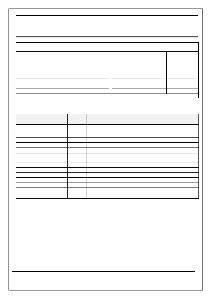
ABSOLUTE MAXIMUM RATINGS
Input Supply Voltage, V
IN
(1)
On/Off
Control Terminal
Voltage, V
CTRL
(1)
20V
20V
Operating Ambient
Temperature Range
-20 to 80 ∞C
Power Dissipation
1.4W(No Heat Sink)
15W(Infinite heat sink)
Storage Temperature
Range
-40 to 150 ∞C
Junction Temperature
(2)
150∞C
Lead Temperature
(Soldering, 10 Seconds)
260 ∞C
Output Current
2A
(1) All are open except GND and applicable terminals
(2) Overheat protection may operate at 125<=Tj<=150∞C.
ELECTRICAL CHARACTERISTICS (
Unless otherwise specified, T
A
= 25 ∞C.)
Parameter
Symbol
Test Conditions
Typical
Limits
Output Voltage
V
O
(3)
, I
OUT
= 1A
5
4.90V
Min
5.20V
Max
Dropout Voltage
V
D
(5)
0.5V
Line Regulation
REG
(LINE)
(4)
, I
OUT
= 5mA
0.5% 2.5%
Load Regulation
REG
(LOAD)
(3)
, 5mA
I
OUT
2A
0.1% 2.0%
Temperature coefficient of
output voltage
T
C
V
O
Tj=0 to 125∞C, Io=5mA
±
0.02%/∞C
ON-state voltage for control
V
C(ON)
(3)
2.0V
min
ON-state voltage for control
I
C(ON)
V
CTRL
=2.7V,
(3)
20uA
Max
OFF-state voltage for control
V
C(OFF)
(3)
0.8V
Max
OFF-state voltage for control
I
C(OFF)
V
CTRL
=0.4V,
(3)
-0.4mA Max
Quiescent Current
I
Q
Io=0A,
(3)
10mA Max
Ripple Rejection Ratio
R
A
Refer to Fig.2 Test Circuit of Ripple
Rejection
55dB 45dB
(Min)
(3) L148T-5:Vin=7V
(4) L148T-5:Vin=6~12V
(5) Input voltage shall be the value when output voltage is 95% in comparison with the initial value.
(6) In case of opening control terminal, output voltage turns on.

L1481T-5
TO-220
3
Low Power-Loss
Voltage Regulators
NIKO-SEM
JUL-15-2002
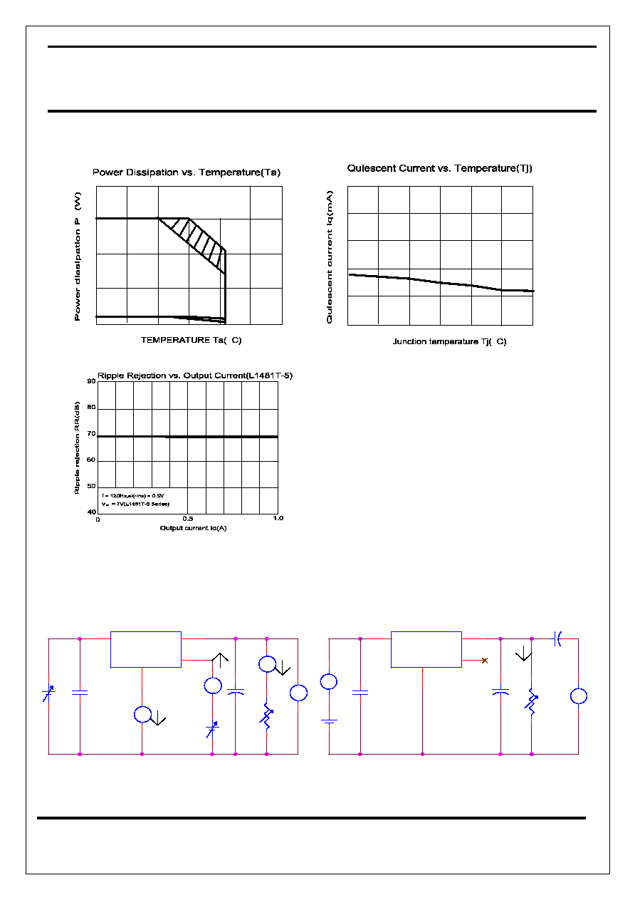
Typical Performance Characteristics
RL=10
RL=5
RL=
3
0
1
0
2
5
6
4
5
7
10
15
20
0
0
10
40
30
50
RL=5
10
5
RL=10
RL=
15
0
1
0
2
0.5
1
6
3
4
5
7
2.5
1.5
2
3
25
0
-25
4.94
4.92
4.96
5.04
4.98
5.00
5.02
5.06
50
75
∞
100
125
∞
3
0
0
20
1
2
80
60
40
100
%
4
5
6
V =7V
IN

L1481T-5
TO-220
4
Low Power-Loss
Voltage Regulators
NIKO-SEM
JUL-15-2002
0
5
0
25
-25
10
D
15
20
100
50
75
∞
125
P :No heat sink
P :With infinite heat sink
D1
D2
P
D2
P
D1
4
-25
0
2
0
25
8
6
10
100
50
75
∞
125
+
47uF
+
47uF
+
47uF
Iq
RR = 20 log [ei(RMS) / eo(RMS)]
Vin
V
Vo
Io =1A
0.33uF
Fig.2 Test Circuit of Ripple Rejection
L1481
2
1
4
3
~
V
eo
A
~
ei
0.33uF
Vin
Vc
Io
A
ei(RMS) = 0.5V
L1481
2
1
4
3
RL
Io
Vin = 7V ( L1481T-5)
Fig.1 Test Circuit
Ic
RL
A
f = 120Hz (sine wave)

L1481T-5
TO-220
5
Low Power-Loss
Voltage Regulators
NIKO-SEM
JUL-15-2002
DEVICE SELECTION GUIDE
Device
L1481T-5
Package
TO-220
Marking
L1481T-5
PIN CONFIGURATIONS
1 2 3
Pin #
Function
1 Vin
2 Vo
3 GND
4 ON/OFF
Control

L1481T-5
TO-220
6
Low Power-Loss
Voltage Regulators
NIKO-SEM
JUL-15-2002
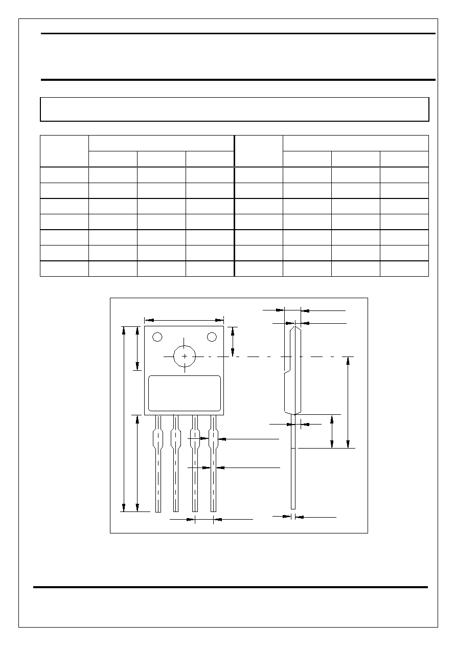
TO-220 (4-Lead) MECHANICAL DATA
mm
mm
Dimension
Min. Typ. Max.
Dimension
Min. Typ. Max.
A
10.5
H
3.4
3.6
3.8
B 7.4 7.6 7.8 I 4.4 4.6 4.8
C
29.1
J
2.65
2.85
3.05
D
14.1
K 15 15.5 16
E 2.5 L 4.5
F 0.63 0.65 0.67 M
1.5
G 1.13 1.15 1.17 N
0.6
D
E
F
C
B
G
H
A
N
K
M
L
J
I


