
- 374 -
LL4001G THRU LL4007G
1.0 AMP Surface Mount Glass Passivated Silicon Rectifiers
Voltage Range
50 to 1000 Volts
Current
1.0 Ampere
Features
a
Plastic package has carries underwriters
Laboratory flammability classification 94V-0
a
Surge overload rating to 30 Ampers peak
a
Ideal
for
printed
circuit
board.
a
Reliable low cost construction utilizing
molded plastic technique results in in-
expensive product.
a
High temperature soldering guaranteed:
250�C / 10 seconds at terminals.
Mechanical Data
a
Solderability per MIL-STD-750, method 208
at terminals.
a
Mounting
position:
Any
a
Weight:
0.12
gram
MELF
Dimensions in inches and (millimeters)
Maximum Ratings and Electrical Characteristics
Rating at 25�C ambient temperature unless otherwise specified.
Single phase, half wave, 60 Hz, resistive or inductive load.
For capacitive load, derate current by 20%
Type Number
LL
4001G
LL
4002G
LL
4003G
LL
4004G
LL
4005G
LL
4006G
LL
4007G
Units
M
aximum
Recurrent P
eak
R
everse
V
oltage
50
100
200
400
600
800
1000
V
Maximum RMS Voltage
35
70
140
280
420
560
700
V
Maximum DC Blocking Voltage
50
100
200
400
600
800
1000
V
Maximum Average Forward Rectified Current
@T
A
= 75�C
1.0
A
Peak Forward Surge Current, 8.3 ms Single
Half Sine-wave Superimposed on Rated Load
(JEDEC method )
30
A
Maximum Instantaneous Forward Voltage
@1.0A
1.1
V
Maximum DC Reverse Current @ T
A
=25�C
at Rated DC Blocking Voltage @ T
A
=125�C
5
100
uA
uA
Typical Junction Capacitance ( Note 1 )
15
pF
Typical Thermal Resistance R
�
JC (Note 2)
50
�C/W
Operating and Storage Temperature Range
T
J
,T
STG
- 65 to + 150
�C
Notes: 1. Measured at 1 MHz and Applied Reverse Voltage of 4.0 Volts D.C.
Notes:
2. Thermal Resistance from Junction to Ambient.
- 375 -
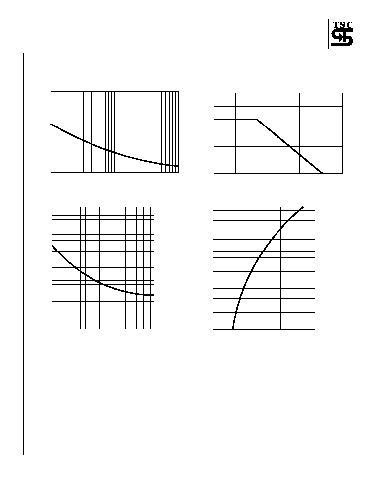
RATINGS AND CHARACTERISTIC CURVES (LL4001G THRU LL4007G)
FIG.4- TYPICAL FORWARD CHARACTERISTICS
INST
ANT
ANEOUS
FOR
W
ARD
CURRENT
.
(A)
1.6
.4
.6
.8
1.0
1.2
1.4
0.01
.1
1.0
10
FORWARD VOLTAGE. (V)
FIG.1- MAXIMUM NON-REPETITIVE FORWARD
SURGE CURRENT
PEAK
FOR
W
ARD
SURGE
CURRENT
.
(A)
1
4
2
6
8 10
20
100
40
80
60
10
50
0
30
20
40
NUMBER OF CYCLES AT 60Hz
FIG.3- TYPICAL JUNCTION CAPACITANCE
JUNCTION
CAP
ACIT
ANCE.(pF)
1
10
100
1.0
10
100
REVERSE VOLTAGE. (V)
FIG.2- MAXIMUM FORWARD CURRENT DERATING
CURVE
A
VERAGE
FOR
W
ARD
CURRENT
.
(A)
25
50
75
100
150
125
175
0
.25
.75
.50
1.00
1.25
1.50
AMBIENT TEMPERATURE. ( C)
o