Æ
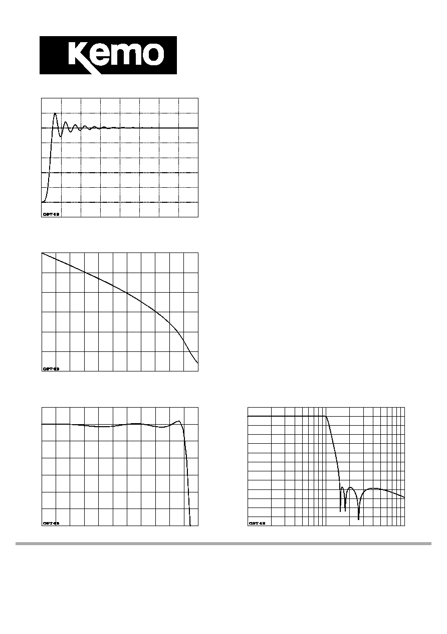
Figure 1: step response vs. time
120%
100%
80%
60%
40%
20%
0%
time, 2/Fc per division from 0 to 16/Fc
Figure 2: passband phase response
0
o
-90
o
-180
o
-270
o
-360
o
-450
o
-540
o
frequency, 0.1Fc per division from 0 to 1.1Fc
Figure 3: passband amplitude response
.5dB
0dB
-.5dB
-1dB
-2dB
-3dB
frequency, 0.1Fc per division from 0 to 1.1Fc
Filter Response: Opt49LP
filter order and type:
n=8 lowpass
basic stopband:
-77dB at 1.5 times Fc
document number:
KT70180
this issue dated:
23 October 1997
Description
The Option 49LP response is a modified elliptic filter; it has
a flat passband with ripple of less than ±0.1dB up to the
cutoff frequency, and a stopband of -77dB starting at 1.5
times cutoff (figures 3 and 4). The phase response of such
filters is quite non-linear (shown in figures 2,6,7 and 9). See
figures 1 and 5, and the table overleaf, for details of
overshoot and settling behaviour.
Applications
This response shape has found wide acceptance as an
alias protection filter for applications where analysis is
carried out in the frequency domain (e.g. FFT analysis), and
wide sampled bandwidth is more important than the time
history of the waveform. Minimum suggested sample rate is
2.5 times the filter cutoff frequency.
Availability
Option 49LP was designed for, and is primarily used on the
VBF10M laboratory filter instrument and the VBF35
multichannel system, though it can be supplied on some
other Kemo products. For a similar, industry-standard
response on most multi-channel Kemo products, see Option
01LP (document number KT70086).
Figure 4: overall frequency response
0dB
-20dB
-40dB
-60dB
-80dB
-100dB
-120dB
frequency, logarithmic scale from 0.1Fc to 10Fc
UK:
Kemo ltd, 3 Brook Court, Blakeney Road
US:
Kemo, Inc, 190 Raven Road
Beckenham, Kent, BR3 1HG
Landrum, SC 29356
tel
(+44) 181 658 3838
tel
864 895 8100
fax
(+44) 181 658 4084
fax
864 895 8900

Filter Response
(page 2)
Figure 5: accuracy vs. time
16bit
15bit
14bit
13bit
12bit
11bit
10bit
time, 2/Fc per division from 0 to 16/Fc
Figure 6: passband phase deviation
100
o
80
o
60
o
40
o
20
o
0
o
-20
o
-40
o
-60
o
-80
o
-100
o
frequency, 0.1Fc per division from 0 to 1.1Fc
Figure 7: passband group delay
4/Fc
3/Fc
2/Fc
1/Fc
0
frequency, 0.1Fc per division from 0 to 1.1Fc
Figure 8: vector error
0dB
-10dB
-20dB
-30dB
-40dB
-50dB
-60dB
-70dB
frequency, 0.1Fc per division from 0 to 1.1Fc
Figure 9: passband phase linearity
10
o
8
o
6
o
4
o
2
o
0
o
-2
o
-4
o
-6
o
-8
o
-10
o
frequency, 0.1Fc per division from 0 to 1.1Fc
Response information for: OPT49
stopband response -77.23dB at 1.525Fc
equivalent attenuation slope 126.84 dB per octave
zero frequency delay 0.7831/Fc
z.f. phase line (used in Figure 6) -281.92deg x f/Fc
mean phase line (used in Figure 9) -326.32deg x f/Fc
best phase line (used in Figure 8) -335.64deg x f/Fc
attenuation: 0.1dB 0.989Fc
0.25dB 0.996Fc
0.5dB 1.005Fc
1dB 1.016Fc
3dB 1.042Fc
6dB 1.068Fc
12dB 1.11Fc
18dB 1.151Fc
24dB 1.194Fc
36dB 1.282Fc
48dB 1.366Fc
60dB 1.438Fc
72dB 1.487Fc
84dB [2.367Fc]
96dB [2.544Fc]
overshoot 19.81% at 1.4/Fc
risetime to 0.996Vin 1.142/Fc
approximate settling time to 9 bits 9.9/Fc
add on for each subsequent bit: 1.427/Fc