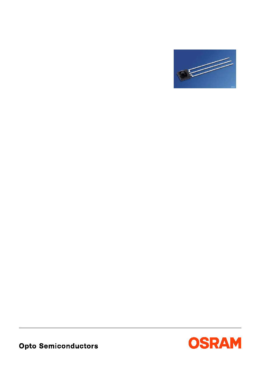
SFH 5110
SFH 5111
IR-Empf‰nger f¸r Fernbedienungen
IR-Receiver for Remote Control Systems
2001-12-10
1
Beschreibung
SFH 5110 und SFH 5111 sind Infrarot-Empf‰nger
f¸r die Erkennung von Signalen aus Infrarot-Fern-
bedienungssystemen und bestehen aus Foto-
diode, Vorverst‰rker, automatischer Verst‰r-
kungsregelung, Bandpaþ-Filter und Demodulator.
Das Geh‰use ist zur Unterdr¸ckung des Tages-
lichteinflusses schwarz eingef‰rbt.
Wesentliche Merkmale
∑
IC mit monolithisch integrierter Fotodiode
(Ein-Chip Lˆsung)
∑
Speziell geeignet f¸r Anwendungen von
940 nm
∑
Hohe Empfindlichkeit
∑
Verschiedene Tr‰gerfrequenzen erh‰ltlich
∑
TTL und CMOS kompatibel
∑
Ausgang: aktiv ,,Low"
∑
Keine externe Beschaltung nˆtig
Anwendungen
∑
Empf‰nger in Fernbedienungen f¸r TV,
Videorecorder, HiFi, Satellitenempf‰nger und
CD-Spieler
∑
Optischer Schalter
Description
SFH 5110 and SFH 5111 are IR receivers to de-
tect light from infrared remote control systems.
The IC includes photodiode, preamplifier, auto-
matic gain control, bandpass and demodulator.
The black-colored package is designed as day-
light-cutoff filter.
Features
∑ IC with monolithic integrated photodiode (single
chip solution)
∑ Especially suitable for applications of 940 nm
∑ High sensitivity
∑ Various carrier frequencies available
∑ TTL and CMOS compatibility
∑ Output: active Low
∑ No external components necessary
Applications
∑ Remote control module for TV sets, VCRs, hi-fi
audio receivers, SAT receivers and compact
disk players
∑ Optical Switch
2001-12-10
2
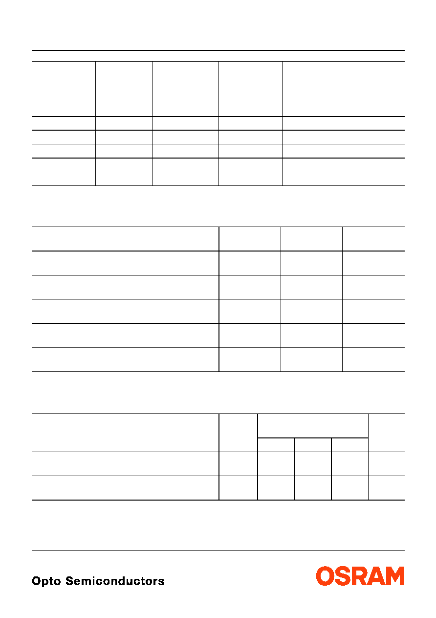
SFH 5110, SFH 5111
Typ
Type
Tr‰gerfrequ.
Carrier
Frequency
kHz
Bestellnr.
Ordering Code
Typ
Type
Tr‰gerfrequ.
Carrier
Frequency
kHz
Bestellnr.
Ordering Code
SFH 5110-30
30
Q62702-P5088
SFH 5111-30
30
Q62702-P5257
SFH 5110-33
33
Q62702-P5089
SFH 5111-33
33
Q62702-P5258
SFH 5110-36
36
Q62702-P5090
SFH 5111-36
36
Q62702-P5259
SFH 5110-38
38
Q62702-P5091
SFH 5111-38
38
Q62702-P5260
SFH 5110-40
40
Q62702-P5092
SFH 5111-40
40
Q62702-P5261
Grenzwerte (
T
A
= 25
∞
C)
Maximum Ratings
Bezeichnung
Parameter
Symbol
Symbol
Wert
Value
Einheit
Unit
Betriebs- und Lagertemperatur
Operation and storage temperature range
T
op
T
stg
≠ 10 ... + 75
≠ 30 ... + 100
∞
C
Betriebsspannung
Supply voltage
V
CC
6.3
V
Ausgangsspannung
Output voltage
V
OUT
6.3
V
Ausgangsstrom
Output current
I
OUT
3
mA
Verlustleistung
Total power dissipation,
T
A
85
∞
C
P
tot
50
mW
Empfohlener Arbeitsbereich
Recommended Operating Conditions
Bezeichnung
Parameter
Symbol
Symbol
Wert
Value
Einheit
Unit
min.
typ.
max.
Betriebstemperatur
Operating temperature
T
op
≠ 10
≠
75
∞
C
Betriebsspannung
Supply Voltage
V
cc
4.5
5.0
5.5
V

SFH 5110, SFH 5111
2001-12-10
3
Kennwerte (
T
A
= 25
∞
C)
Characteristics
Bezeichnung
Parameter
Symbol
Symbol
Wert
Value
Einheit
Unit
min.
typ.
max.
Stromaufnahme,
V
CC
= 5 V,
E
= 0
Current consumption
I
CC
≠
1.3
≠
mA
Wellenl‰nge der max. Fotoempfindlichkeit
Wavelength of max. sensitivity
s max
≠
940
≠
nm
Spektraler Bereich der Fotoempfindlichkeit
Spectral range of sensitivity
830
≠
1100
nm
Ausgangsspannung
Output voltage
Output "High" - (
I
q
= 10
µ
A)
Output "Low" - (
I
q
= 500
µ
A)
V
OUT high
V
OUT low
V
S
≠ 0.5
≠
≠
≠
≠
0.5
V
Tr‰gerfrequenz
Carrier frequency
f
0
≠
30
33
36
38
40
≠
kHz
Min. Bestrahlungsst‰rke (Testsignal, s. Fig. 3)
Min. Threshold irradiance (test signal, see Fig. 3)
f
=
f
0
,
t
p,
I
= 600
µ
s
E
e min
≠
0.35
0.5
mW/m
2
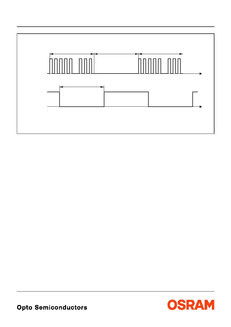
Min. Eingangspulsbreite ,,ON"
(Testsignal, s. Fig. 3)
1)
Min. Input pulse width "ON"
(test signal, see Fig. 3)
1)
1)
Die volle Empfindlichkeit wird bei einer Burstl‰nge von mindestens 6 Pulsen erreicht. Die Reichweite bei
Verwendung eines typischen Senders (SFH 4510/SFH 4515,
I
F
= 500 mA) betr‰gt etwa 30 m.
1)
A minimum burst length of 6 pulses is necessary for full sensitivity. The transmission distance with a typical
transmitter (SFH 4510/SFH 4515,
I
F
= 500 mA) is about 30 m.
t
p,I
6/
f
O
≠
≠
µ
s
Ausgangspulsbreite ,,ON"
(Testsignal, s. Fig. 3)
Output pulse width "ON" (test signal, see Fig. 3,
E
e
= 1 mW/m
2
)
t
p,O
t
p,
I
≠ 6/
f
O
≠
t
p,I
+ 6/
f
O
µ
s
50%-Filterbandbreite,
f
=
f
O
,
E
V
= 0,
V
CC
= 5 V
50%-Filter bandwidth
f
50%
3
≠
6
kHz

2001-12-10
4
SFH 5110, SFH 5111
Figure 1
Blockschaltbild
Block Diagram
Figure 2
Externe Beschaltung
External Circuit
OHF00404
Demodulator
Bandpass
AGC
Control
Input
GND
V
CC
PIN
Circuit
23 k
OUT
OHF00430
3
1
2
SFH 5110-xx
>10 k
100
4.7
µ
F
µ
C
optional
*)
*)
+5 V
GND
*)
only necessary to suppress power supply disturbances
_
<
<
_
SFH 5111-xx
SFH 5110, SFH 5111
2001-12-10
5
Figure 3
Optisches Testsignal
Optical Test Signal
OHF00399
=
t
p, o
± 6 / f
o
p, I
t
t
t
t
p, I
t
off, I
t
p, I
Burst wave: carrier frequency f
o
, Duty cycle = 0.5
Transmitter
Detector
(Output Signal)