HIGH VOLTAGE RECTIFIER
VOLTAGE RANGE
1200 to 5000 Volts
R1200F THRU R5000F
CURRENT
0.2 to 0.5 Ampere
FEATURES
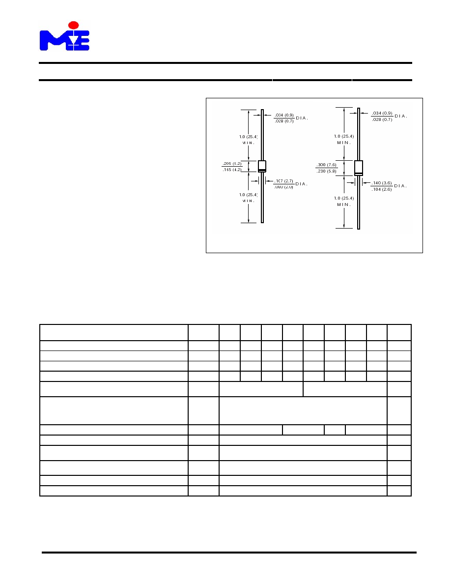
DO-41
DO-15
∑
Low Leakage
∑
High Surge Capacity
∑
High current capability
∑
High Temperature soldering guaranteed:
260
O
C / 10 second, 0.375" (9.5mm) lead length
MECHANICAL DATA
∑
Case: Transfer molded plastic
∑
Epoxy: UL94V ≠ 0 rate flame retardant
∑
Polarity: Color Band denotes cathode end
∑
Lead: Plated axial lead, solderable per
MIL ≠ STD-202E Method 208C
∑
Mounting Position: Any
∑
Weight: 0.012 ounce, 0.33 gram (DO-41)
0.014 ounce, 0.39 gram (DO-15)
MAXIMUM RATINGS AND ELECTRICAL CHARACTERISTICS
∑
Ratings at 25
O
C ambient temperature unless otherwise specified
∑
Single Phase, half wave, 60Hz, resistive or inductive load
∑
For capacitive load derate current by 20%
SYMBOLS
R
1200F
R
1500F
R
1800F
R
2000F
R
2500F
R
3000F
R
4000F
R
5000F
UNIT
Package
DO-41 DO-41 DO41 DO-41 DO-15 D0-15 DO-15 DO-15
Maximum Repetitive Peak Reverse Voltage
V
RRM
1200 1500 1800 2000 2500 3000 4000 5000 Volts
Maximum RMS Voltage
V
RMS
840 1050 1260 1400 1750 2100 2800 3500 Volts
Maximum DC Blocking Voltage
V
DC
1200 1500 1800 2000 2500 3000 4000 5000 Volts
Maximum Average Forward Rectified Current,
0.375" (9.5mm) lead length
at T
A
= 50
O
C
I
(AV)
500 200
mA
Peak Forward Surge Current
8.3mS single half sine wave superimposed on
rated load (JEDEC method)
I
FSM
30 Amps
Maximum Instantaneous Forward Voltage @ 0.5/0.2A
V
F
2.5 6.0
5.0
6.5
Volts
Maximum DC Reverse Current at Rated T
A
= 25
O
C
I
R
5.0 µA
Maximum Full Load Reverse Current, Full Cycle average
0.375" (9.5mm) lead length
at T
A
= 55
O
C
I
R(AV)
100 µA
Maximum Reverse Recovery Time
Test conditions I
F
=
0.5A, I
R
= 1.0A, I
RR
= 0.25A
t
rr
500 nS
Operating Junction Temperature Range
T
J
(-65 to +150)
O
C
Storage Temperature Range
T
STG
(-65 to +150)
O
C
Sep-03, Rev A
Micro Electronic Instrument Inc.
