 | ÐлекÑÑоннÑй компоненÑ: RC2202 | СкаÑаÑÑ:  PDF PDF  ZIP ZIP |
Äîêóìåíòàöèÿ è îïèñàíèÿ www.docs.chipfind.ru
RC220x
©
2005 Radiocrafts AS
RC220x Data Sheet (rev. 1.0)
Page 1 of 17
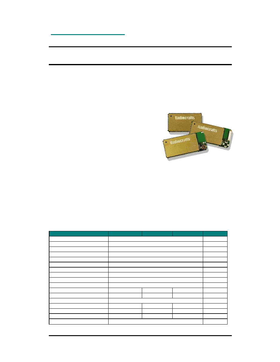
ZigBeeTM- Ready RF Transceiver Modules
Product Description
The RC2200/2202/2204 RF Transceiver Modules are a series of compact surface-mounted
modules specially designed for the ZigBeeTM protocol stack for wireless star and mesh
networks based on IEEE 802.15.4 compliant PHY and MAC layers providing 16 channels in
the 2.45 GHz world-wide license-free ISM band. The complete shielded module is only 16.5 x
29.2 x 3.5 mm, optionally available with integrated antenna or RF connector. Up to 128 kB
flash memory, 32 digital and analogue I/Os including an 8 channel 10 bit ADC, UART and SPI
interfaces. The powerful internal resources make it possible to embed the complete
application in this tiny module.
Applications
·
Home control and industrial automation
·
Building automation
·
OEM equipment
·
Fleet and inventory management
Features
·
ZigBee-ready / IEEE 802.15.4 compliant PHY and MAC
·
Memory space for Full Function Device (FFD)
·
16.5 x 29.2 x 3.5 mm compact shielded module for SMD mounting
·
Up to 128 kB Flash memory, 4 kB SRAM, 4 kB EEPROM
·
32 digital and analogue I/Os, 8 channel 10 bit ADC
·
UART, SPI and JTAG interfaces
·
On-board 32.768 kHz real time clock (RTC)
·
High performance direct sequence spread spectrum (DSSS) RF transceiver
·
16 channels in the 2.45 GHz ISM band
·
Integrated antenna or MMCX RF connector options
·
2.7 3.6 V supply voltage
·
MCU and on-board RTC support ultra low power modes
·
Conforms with EN 300 440 (Europe), FCC CFR 47 part 15 (US), ARIB STD-T66 (Japan)
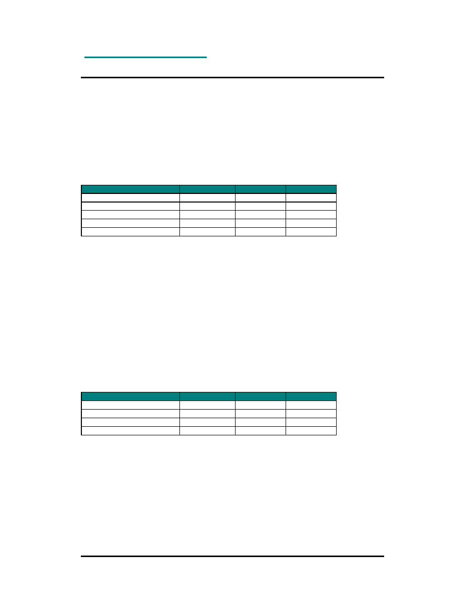
Quick Reference Data
Parameter
RC2200
RC2202
RC2204
Unit
Frequency band
2.400-2.4835
GHz
Number of channels
16
Data rate
250
kbit/s
Max output power
0
dBm
2
nd
harmonic
-37
dBm
3
rd
harmonic
-51
dBm
Sensitivity (PER 1%)
-94
dBm
Adjacent Channel Rejection
39
dB
Alternate Channel Rejection
55
dB
Supply voltage
2.7 3.6
Volt
Current consumption, RX
30
26
30
mA
Current consumption, TX
27
23
27
mA
Current consumption, PD
1.3
uA
Flash memory
128
32
64
kB
RAM
4
2
4
kB
EEPROM
4
1
2
kB
Operating Temperature
-30 to +85
°
C
PRELIMINARY INFORMATION. Specifications and information herein are subject to change without notice.
RC220x
©
2005 Radiocrafts AS
RC220x Data Sheet (rev. 1.0)
Page 2 of 17
Quick Product Introduction
The RC220x series of modules are specially designed to meet the IEEE 802.15.4 standard
used by ZigBee and a variety of proprietary network protocols. Using the module together
with the Chipcon / Figure 8 Wireless Z-stack or any other ZigBee network implementation
makes it a powerful platform to build any ZigBee profile and application. The module contains
qualified RF hardware and enough processor power to run the complete ZigBee mesh
network protocol for a full function device including the application.
Using a pre-qualified module is the fastest way to make a ZigBee product and shortest time to
market. Because it contains all the RF HW and MCU resources you need in a 100% RF
tested and pre-qualified module shorten the qualification and approval process. No RF design
or expertise is required to add powerful wireless networking to the product. As an option you
can even get the module with integrated antenna or coaxial MMCX connector. In the simplest
case like a home light remote control you only need an external battery and a pushbutton.
You may find more general information on how to build a ZigBee application Radiocrafts
application note AN003.
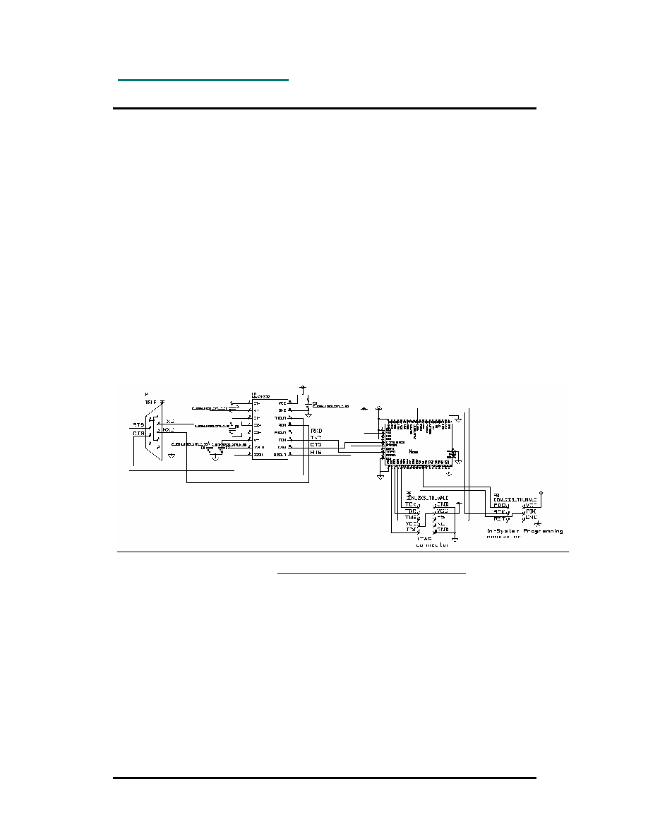
Typical Application Circuit
Below is shown a Serial Port application circuit. The JTAG and ISP are also shown.
Full resolution schematic is found in
RC2200_Application_Circuit_SPP_1_0.pdf

RC220x
©
2005 Radiocrafts AS
RC220x Data Sheet (rev. 1.0)
Page 3 of 17
Frequently Asked Questions
What is IEEE 802.15.4?
It is a standard for low data rate wireless Personal Area Networks (PAN) focusing on low
power, low cost and robustness. It defines a Physical layer (PHY) and a Medium Access
Control layer (MAC) and is the basis for the open ZigBee protocol or proprietary protocols.
What is ZigBee?
ZigBee is an open global standard aimed for wireless network communication between
devices in home control, industrial and building automation applications. It provides star,
cluster tree and mesh topologies (see illustration). The multi-hop and ad-hoc routing
properties is ideal for non-static networks covering a house or building.
How do I implement my application?
Your application can be implemented on top of the ZigBee stack sharing the resources in the
embedded microcontroller. An extensive number of digital and analogue I/Os can be used to
directly interface sensors, switches and actuators. Timing applications can use the on-board
32 kHz real-time clock. Ultra low power modes are ideal for battery operation.
What about the ZigBee stack?
In principle any third-party ZigBee stack implementation can be used with the module. But in
particular the module is intended for use with the Chipcon / Figure 8 Wireless Z-stack and
MAC. The Z-stack royalty fee is included in the module cost. The Z-stack license and
software development tools are available from Chipcon.
What development tools do I need?
The following development tools for the embedded MCU (Atmel mega128) are recommended
and available free of charge:
·
WinAVR / AVR GCC / Programmer's Notepad
·
Atmel AVR Studio
The Atmel JTAG ICE mkII can be used to download the program into the embedded
controller.
RC220x
©
2005 Radiocrafts AS
RC220x Data Sheet (rev. 1.0)
Page 4 of 17
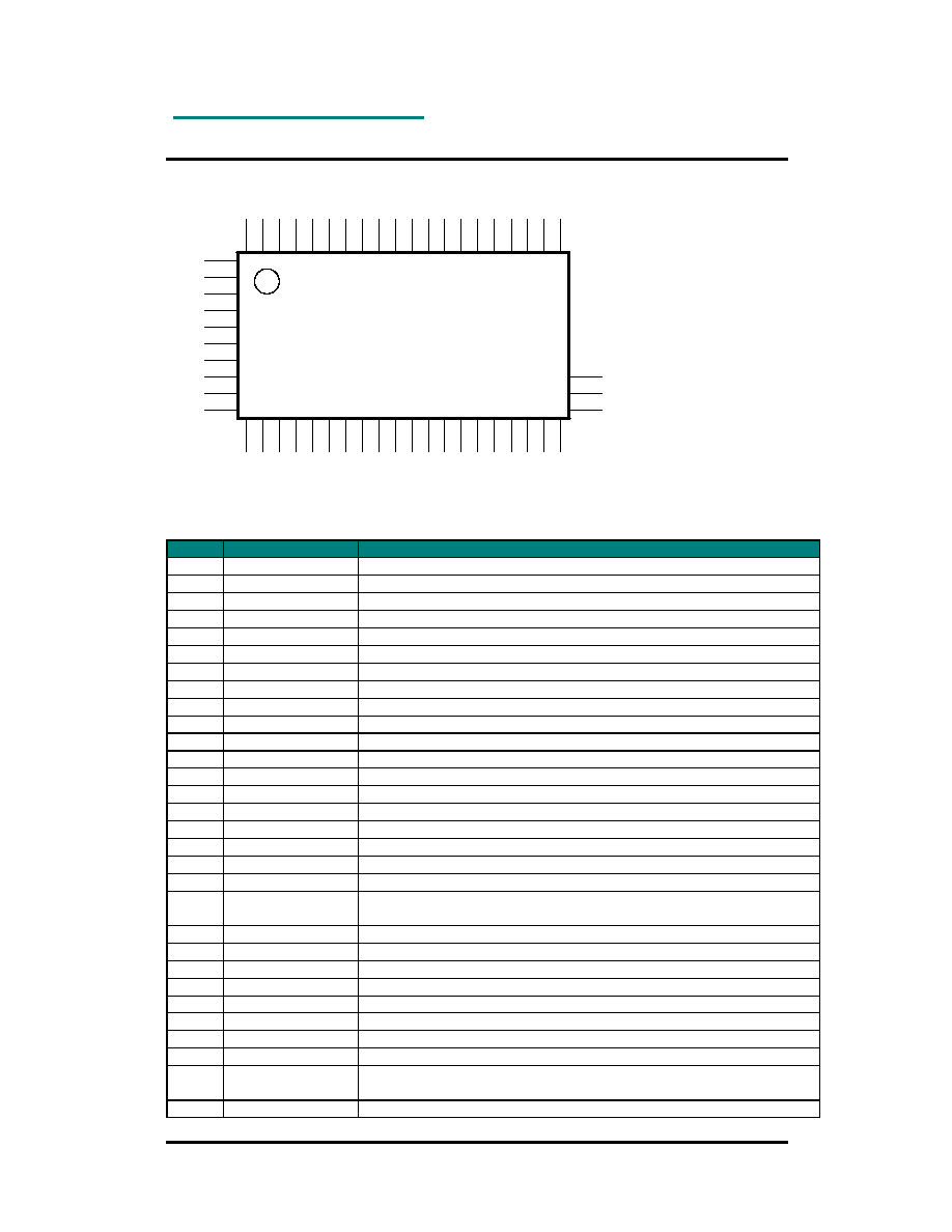
Pin Assignment
1
10
11
30
33
31
53
34
Pin Description
Pin no Pin name
Description and internal MCU connection
1
GND
System ground
2
VCC
Supply voltage input
3
PG0
Digital I/O, PG0
4
GND
System ground
5
CTS1
Digital I/O, PD7 / CTS1
6
RTS1
Digital I/O, PD5 / RTS1
7
PG2
Digital I/O, PG2
8
TXD1
Digital I/O, PD3 / TXD1 / INT3
9
RXD1
Digital I/O, PD2 / RXD1 / INT2
10
GND
System ground
11
GND
System ground
12
ADC7
Digital or analogue I/O, PF7, JTAG TDI
13
ADC6
Digital or analogue I/O, PF6, JTAG TDO
14
ADC5
Digital or analogue I/O, PF5, JTAG TMS
15
ADC4
Digital or analogue I/O, PF4, JTAG TCK
16
ADC3
Digital or analogue I/O, PF3
17
ADC2
Digital or analogue I/O, PF2
18
ADC1
Digital or analogue I/O, PF1
19
ADC0
Digital or analogue I/O, PF0
20
AREF
Analogue reference voltage pin for the internal A/D Converter.
Internally decoupled with 22nF.
21
PE0
Digital I/O, PE0, ISP PDI for RC2200 and RC2204
22
PE1
Digital I/O, PE1, ISP PDO for RC2200 and RC2204
23
PE2
Digital I/O, PE2
24
PE3
Digital I/O, PE3
25
PE4
Digital I/O, PE4 / INT4
26
PE5
Digital I/O, PE5 / INT5
27
PE6
Digital I/O, PE6 / INT6
28
PE7
Digital I/O, PE7 / INT7
29
1.8V
Internally regulated voltage. Normally not connect. May be used for
AREF
30
GND
System ground

RC220x
©
2005 Radiocrafts AS
RC220x Data Sheet (rev. 1.0)
Page 5 of 17
31
GND
System ground
32
RF
RF I/O connection to antenna, 50 Ohm. Do not connect for integrated
antenna or connector variant.
33
GND
System ground
34
GND
System ground
35
Reserved
Do not connect, PB0
36
SCLK
SPI interface must be shared with MAC, PB1, ISP SCK
37
SI
SPI interface must be shared with MAC, PB2, PDI for RC2202
38
SO
SPI interface must be shared with MAC, PB3, PDO for RC2202
39
PB4
Digital I/O, PB4
40
Reserved
Do not connect, PB5
41
Reserved
Do not connect, PB6
42
PB7
Digital I/O, PB7
43
TOSC2
Internal 32.768 kHz oscillator
44
RESET
Internal MCU reset. Active low with internal pull-up.
45
Reserved
Do not connect, PD0 / INT0
46
Reserved
Do not connect, PD1 / INT1
47
RXD1
Same as pin 9
48
TXD1
Same as pin 8
49
Reserved
Do not connect, PD4
50
RTS1
Same as pin 6
51
Reserved
Do not connect, PD6
52
CTS1
Same as pin 5
53
GND
System ground
Note 1: UART interface: Pin 8 TXD1, pin 9 RXD1, pin 5 CTS1, pin 6 RTS1
Note 2: SPI interface: Pin 36 SCLK, pin 37 SI, pin 38 SO (chip select at any digital I/O) must be shared with internal
MAC software
Note 3: ISP (In-System Programming) interface: Pin 36 SCK, pin 21 PDI, pin 22 PDO, pin 44 RESET for RC2200 and
RC2204. Pin 36 SCK, pin 37 PDI, pin 38 PDO, pin 44 RESET for RC2202. See page 8 for more information.
Note 4: JTAG interface: Pin 12 TDI, pin 13 TDO, pin 14 TMS, pin 15 TCK, pin 44 RESET. See page 8 for more
information.
RC220x
©
2005 Radiocrafts AS
RC220x Data Sheet (rev. 1.0)
Page 6 of 17
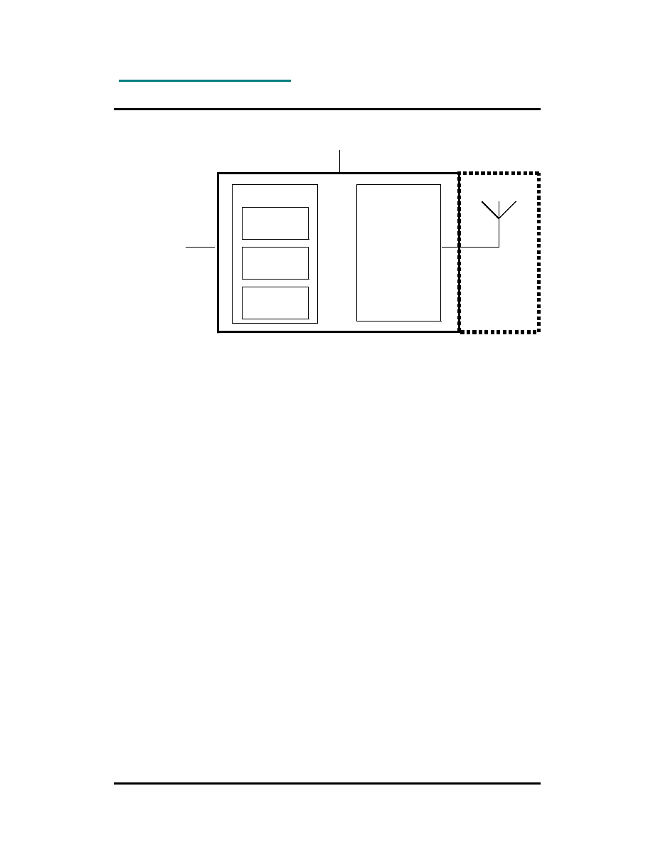
Block Diagram
IEEE 802.15.4
MAC
8-bit MCU
IEEE 802.15.4
RF Transceiver
ZigBee
TM
Network
User
Application
Integrated
antenna
or
RF connector
(optional)
Digital/Analogue I/O
UART interface
SPI interface
2.7-3.6 V
Embedded resources
MCU: Atmel mega128L, mega64L or mega325
PHY/MAC: Chipcon CC2420
Chipcon / Figure 8 Wireless Z-stack royalty fee included
Circuit Description
The module contains a micro controller unit (MCU) and an IEEE 802.14.4 compliant RF
transceiver with internal voltage regulator. The module is intended for running the ZigBee
network protocol.
The application software together with the ZigBee protocol software stack can be
programmed in Flash memory through JTAG or ISP interfaces. The JTAG interface can also
be used for debugging. The MCU runs at 8 MHz and contains on-chip RAM and non-volatile
EEPROM memory.
The MCU controls the RF transceiver through an SPI interface and hardware handshake
signals. The firmware controlling the RF transceiver is part of the MAC software. The antenna
output is internally matched to 50 Ohms, optionally using an integrated antenna.
The supply voltage is connected to the VCC pin. The module contains an internal low noise
voltage regulator for the RF transceiver, and can therefore operate over a wide supply voltage
range. The regulated voltage is available at the 1.8V pin (pin 29), but should not be used to
supply external circuits except for connection to AREF, being a reference for the internal A/D
converter.
The module provides 2 UART interfaces, SPI interface, JTAG interface. Totally 32 I/O pins
are available to the user. 8 pins can be used for the internal 10 bit A/D converter. 6 of the
digital I/Os have interrupt features.
The MCU provides several low power modes with can be utilized to reduce the current
consumption in battery operated applications. An internal 32 kHz crystal oscillator can be
used for real-time clock and timer applications.
For further details on the RF transceiver (Chipcon CC2420) and MCU (Atmel mega128L,
mega64L or mega325), please consult the respective data sheets.

RC220x
©
2005 Radiocrafts AS
RC220x Data Sheet (rev. 1.0)
Page 7 of 17
IEEE 802.15.4
The IEEE 802.15.4 standard, approved in May 2003, provides a worldwide standard for
Personal Area Networks or short distance wireless networks for low data rate solutions with
long battery life and very low complexity. It defines a Physical layer (PHY) and a Medium
Access Control layer (MAC) and is the basis for the open ZigBee protocol or proprietary
protocols. The typical applications are home and building automation, industrial control and
monitoring systems, wireless sensor networks, remote controls and consumer electronics.
The module complies with the IEEE 802.15.4 standard operating in the 2.45 GHz band. It
uses direct sequence spread spectrum (DSSS) with 2 Mc/s chip rate giving a raw data rate of
250 kbit/s 16 channels are available in the 2.45 GHz band, channel 11 26 (channels 0-10
are reserved for use in the 868 and 915 MHz bands).
For more information on the standard, please consult
www.ieee802.org/15/pub/TG4.html
Reference:
IEEE std 802.15.4 -2003: Wireless Medium Access Control (MAC) and Physical layer (PHY)
specifications for Low Rate Wireless Personal Area Networks (LR-WPANs)
http://standards.ieee.org/getieee802/download/802.15.4-2003.pdf
The ZigBee Protocol
The ZigBee Alliance is an association of companies working together to enable reliable, cost-
effective, low-power, wirelessly networked, monitoring and control products based on an open
global standard. The ZigBee Alliance is a rapidly growing, non-profit industry consortium of
leading semiconductor manufacturers, technology providers, OEMs and end-users worldwide.
Membership is open to all. The ZigBee Alliance, in collaboration with the IEEE, is defining the
network, security, and application layers above the IEEE 802.15.4 PHY and MAC layers. This
cooperation has resulted in an easy-to-use, standards-based wireless network platform
optimised for wireless monitoring and control applications. For more information about the
ZigBee Alliance and the ZigBee standard, please consult
www.zigbee.org
The module is intended for using the ZigBee protocol. However, other proprietary network
protocols can also be implemented using the module.
The ZigBee stack implementation from Chipcon/Figure 8 Wireless is recommended as it
provides seamless integration with the module. However, third party stack implementations
can also be used provided they support the Chipcon MAC firmware.
RC220x
©
2005 Radiocrafts AS
RC220x Data Sheet (rev. 1.0)
Page 8 of 17
JTAG Interface
The module offers a JTAG interface for Flash and EEPROM programming, as well as for
debugging.
Programming through the JTAG interface requires control of the four JTAG specific pins:
TCK, TMS, TDI, and TDO. Control of the reset and clock pins is not normally required. To be
able to use the JTAG interface, the JTAGEN Fuse must be programmed. The device is
default shipped with the fuse programmed. For further information, please refer to the
respective MCU data sheet.
The table below show the JTAG pin mapping.
Signal
RC2200
RC2202
RC2204
TDI
12
12
12
TDO
13
13
13
TMS
14
14
14
TCK
15
15
15
RESET
44
44
44
Supply and ground must also be connected during programming.
ISP Interface
The module offers an In-System Programming (ISP) interface for Flash and EEPROM
memory programming. The fastest way to do firmware downloading in manufacturing is
through the ISP interface rather then the JTAG interface.
The memory arrays can be programmed using the serial interface bus while RESET is pulled
to GND. The serial interface consists of pins SCK, PDI/MOSI (input) and PDO/MISO (output).
The RC2200 and RC2204 use the PDI and PDO pins (shared with UART0), while RC2202
use MOSI and MISO (shared with SPI interface), see table below.
After RESET is set low, the Programming Enable instruction needs to be executed first before
program/erase operations can be executed. More information is available in the respective
MCU data sheets.
The table below show the pin mapping for ISP programming.
Signal
RC2200
RC2202
RC2204
PDI
21
37
21
PDO
22
38
22
SCL
36
36
36
RESET
44
44
44
Supply and ground must also be connected during programming.

RC220x
©
2005 Radiocrafts AS
RC220x Data Sheet (rev. 1.0)
Page 9 of 17
Power Management
The ZigBee protocol allows End Devices to be powered down, while Routers must be
powered all the time in order to handle packet routing. Battery operated devices should be
End Devices in order to reduce the power consumption to a minimum.
The module can be set in several sleep modes using the features of the MCU and turning off
the RF transceiver. Sleep modes enable the application to shut down unused modules in the
MCU, thereby saving power. The MCU provides various sleep modes allowing the user to
tailor the power consumption to the application's requirements. To enter any of the six sleep
modes available in the ATmega128L/64L/325, the SE bit in MCUCR must be written to logic
one and a SLEEP instruction must be executed. The SM2, SM1, and SM0 bits in the MCUCR
Register select which sleep mode (Idle, ADC Noise Reduction, Power-down, Power-save,
Standby, or Extended Standby) will be activated by the SLEEP instruction. For further
information on using the various sleep modes, please refer to the respective MCU data
sheets.
In applications like switch remote controls, the switch buttons should be connected to one of
the interrupt pins. PIR sensors (for occupancy detection) and light sensors should also be
using pin interrupts to awake the device from power down mode (PD). During PD the pin
interrupts are still active.
Temperature sensors, humidity sensors and similar could be polled at regular intervals using
the 32 kHz low frequency oscillator timer to awake the device. In this case using the Idle
mode with 32 kHz oscillator is recommended. This mode is not available for RC2202.
In order to ensure that the internal Power On Reset (POR) operates correctly, the maximum
rise-time specification for VCC must be met (see Electrical Specifications). If longer rise-time
is expected it is recommended to use an external POR circuit attached to the RESET pin (see
Application Note AN001). Slow VCC rise-time or short power interruptions may cause
improper operation that is not handled by the internal POR. In this case the RESET should
be activated in order to ensure proper start-up.
RC220x
©
2005 Radiocrafts AS
RC220x Data Sheet (rev. 1.0)
Page 10 of 17
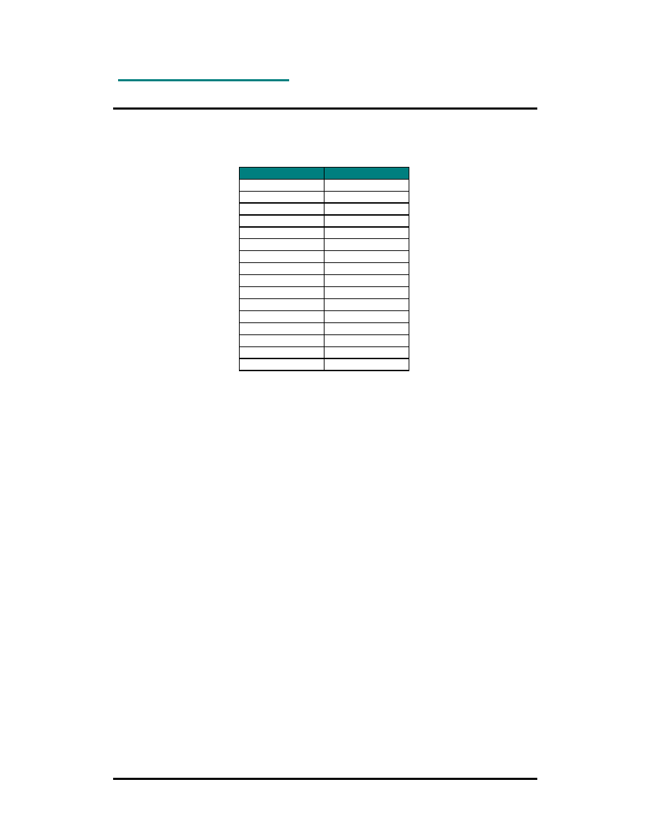
RF Frequency, Output Power Levels and Data Rates
The following table shows the RF channels as defined by the IEEE 802.15.4 standard.
RF channel
Frequency
11
2405 MHz
12
2410 MHz
13
2415 MHz
14
2420 MHz
15
2425 MHz
16
2430 MHz
17
2435 MHz
18
2440 MHz
19
2445 MHz
20
2450 MHz
21
2455 MHz
22
2460 MHz
23
2465 MHz
24
2470 MHz
25
2475 MHz
26
2480 MHz
For proprietary solutions (non-IEEE 802.15.4), the RF transceiver can be programmed in
steps of 1 MHz.
The output power level can be configured from the firmware in the range -25 to 0 dBm.
The RF transceiver uses direct sequence spread spectrum (DSSS) with 2 Mchip/s chip rate,
giving a raw data rate of 250 kbit/s. The modulation format is Offset Quadrature Phase Shift
Keying (O-QPSK). The DSSS makes the communication link robust in noisy environments
when sharing the same frequency band with other applications.
The use of RF frequencies and maximum allowed RF power is limited by national regulations.
The RC2200 series is complying with the applicable regulations for the world wide 2.45 GHz
ISM band.
Specifically it complies with the European Union R&TTE directive meeting EN 300 328 and
EN300 440 class 2. It also meets the FCC CFR47 Part15 regulations for use in the US and
the ARIB T-66 for use in Japan.

RC220x
©
2005 Radiocrafts AS
RC220x Data Sheet (rev. 1.0)
Page 11 of 17
Antenna and Range Considerations
As an option the module is delivered with an integrated antenna (RC220xAT). This is highly
recommended for most applications, as this gives a very compact solution containing all the
critical RF parts within the module.
Range testing using the integrated antenna shows these typical distances:
·
110 meter outdoor line-of-sight (LOS)
·
10-30 meters indoors depending on building material and construction
·
10-15 meters when passing through floors
·
25-30 meters in the same floor
The variation between different orientations of the antenna measured outdoors line-of-sight is
typically within +/- 20%.
The integrated antenna is a compact ceramic antenna working as a quarter-wave resonant
antenna. Due to the dielectric ceramic material the antenna is shorter than a normal quarter
wave antenna (in air), still providing high radiation efficiency (typical 1 dBi). The antenna is
matched for use in the 2.45 GHz band. The radiating part of the antenna is the white ceramic
component located outside the shield can. The radiation pattern from the antenna is similar to
the donut-shaped radiation from a quarter wave antenna. That is, the maximum radiation is in
the plane normal to the length axis of the antenna. For best possible omni-directional
radiation the module should be oriented so that the antenna is vertical. To achieve the very
best range the transmitting and receiving antenna should be oriented the same way, ensuring
the same polarity at both devices. However, indoors reflections of the radio waves in metallic
structures tend to spread the polarisation, so even if same orientation is not possible,
communication will still take place, but the range is somewhat shorter, typically by 20%.
The antenna should be kept away (> 10mm) from metallic or other conductive and dielectric
materials, and should never be used inside a metallic enclosure.
Compared to lower frequencies, operation at 2.45 GHz is more limited to LOS. Reflections
from walls and other objects may give multi-path fading resulting in dead-zones. The ZigBee
mesh network topology is used to overcome this fading as it allows for alternative routing
paths. The mesh network is therefore highly recommended for increased reliability and
extended coverage throughout buildings.
In applications where the module must be placed in a metallic enclosure, an external antenna
must be used. The MMCX connector option (RC220xMM) can then be used to launch a
coaxial cable connecting to the external antenna. It is not recommended to connect a whip
antenna directly to the MMCX connector as it does not support the mechanical strength
required for necessary robustness with such an antenna.
If the option without antenna or MCCX is chosen (RC220x), the RF output must be connected
to an antenna through the RF pin. The RF input/output is matched to 50 Ohm. If the antenna
or antenna connector is placed away from the module at the motherboard, the track between
the RF pin and the connector should be a 50 Ohm transmission line.
On a two layer board made of FR4 the width of a microstrip transmission line should be 1.8
times the thickness of the board, assuming a dielectric constant of 4.8. The line should be run
at the top of the board, and the bottom side should be a ground plane.
Example: For a 1.6 mm thick FR4 board, the width of the trace on the top side should be 1.8 x
1.6 mm = 2.88 mm.

RC220x
©
2005 Radiocrafts AS
RC220x Data Sheet (rev. 1.0)
Page 12 of 17
The simplest antenna to use is the quarter wave whip antenna. A quarter wave whip antenna
above a ground plane yields 37 Ohm impedance and a matching circuit for 50 Ohm are
usually not required.
A PCB antenna can be made as a copper track where the ground plane is removed on the
back side. The rest of the PCB board should have a ground plane as large as possible,
preferably as large as the antenna itself, to make it act as a counterweight to the antenna. If
the track is shorter than a quarter of a wavelength, the antenna should be matched to 50
ohms.
The length of a quarter wave antenna is 2.9 cm at 2450 MHz.
RC220x
©
2005 Radiocrafts AS
RC220x Data Sheet (rev. 1.0)
Page 13 of 17
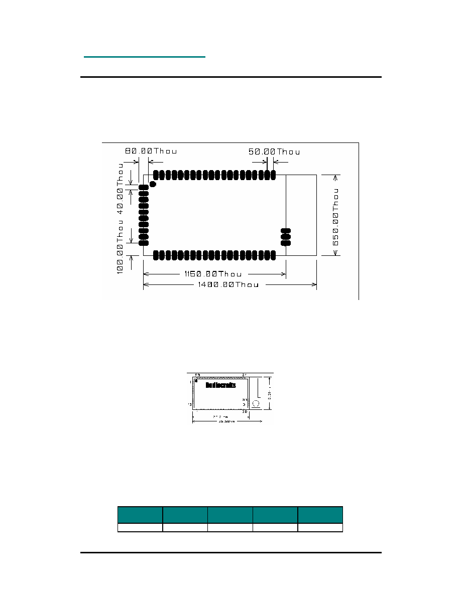
PCB Layout Recommendations
The recommended layout pads for the module are shown in the figure below (top view, pin 1
is in upper left corner, see pin assignment at page 4). All dimensions are in thousands of an
inch (mil). The circle in upper left corner is an orientation mark only, and should not be a part
of the copper pattern.
The area underneath the module should be covered with solder resist in order to prevent
short circuiting the test pads on the back side of the module. A solid ground plane is
preferred. Unconnected pins should be soldered to the pads, and the pads should be left
floating. For the module version with integrated antenna or MMCX connector, the RF pad (pin
31) can be soldered, but the pad should not be connected further. The two ground pads (pin
30 and 32 on the right side) should be grounded for all variants.
Mechanical Drawing
Mechanical Dimensions
The module size is 0.65" x 1.15" x 0.14" (16.5 x 29.2 x 3.5 mm) without the antenna / MMCX
connector. The length is 1.4" (35.6 mm) with the optional antenna / MMCX RF connector.
Carrier Tape and Reel Specification
Carrier tape and reel is in accordance with EIA Specification 481.
Tape width Component
pitch
Hole pitch
Reel
diameter
Units per
reel
56 mm
20 mm
4 mm
13"
Max 800
RC220x
©
2005 Radiocrafts AS
RC220x Data Sheet (rev. 1.0)
Page 14 of 17
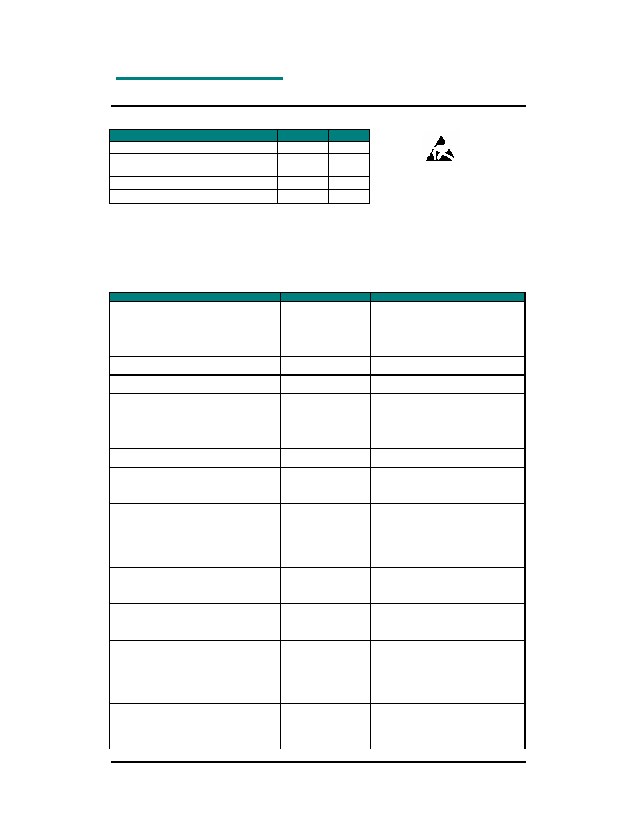
Absolute Maximum Ratings
Parameter
Min
Max
Unit
Supply voltage, VCC
-0.3
3.6
V
Voltage on any pin
-0.3
VCC+0.5 V
Input RF level
10
dBm
Storage temperature
-50
150
°
C
Operating temperature
-30
85
°
C
Caution ! ESD sensitive device.
Precaution should be used when handling
the device in order to prevent permanent
damage.
Under no circumstances the absolute maximum ratings given above should be violated.
Stress exceeding one or more of the limiting values may cause permanent damage to the
device.
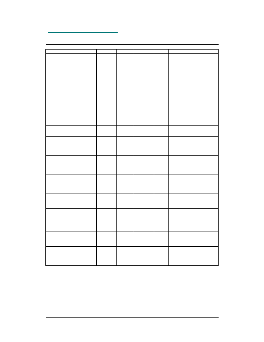
Electrical Specifications
T=25
°
C, VCC = 3.0V if nothing else stated.
Parameter
Min
Typ.
Max
Unit
Condition / Note
Operating frequency
2400
2483
MHz
Programmable in 1 MHz steps,
5 MHz steps for IEEE 802.15.4
compliance
Number of channels
16
For IEEE 802.15.4 compliance
Channel spacing
5
MHz
For IEEE 802.15.4 compliance
Input/output impedance
50
Ohm
Data rate
250
kbit/s
DSSS chip rate
2
Mc/s
Frequency stability
+/-40
ppm
Transmit power
-25
0
dBm
Programmable from firmware
Harmonics
2
nd
harmonic
3
rd
harmonic
-37
-51
Spurious emission, TX
30 1000 MHz
1-12.75 GHz
1.8-1.9 GHz
5.15-5.3 GHz
-36
-30
-47
-47
dBm
Complies with EN 300 328, EN
300 440, FCC CRF47 Part 15
and ARIB STD-T66
Sensitivity
-94
dBm
PER = 1%
Adjacent channel rejection
+/- 5 MHz
46/39
dB
At -82 dBm, PER = 1%.
0 dB for IEEE 802.15.4
compliance
Alternate channel selectivity
+/- 10 MHz
58/55
dB
At -82 dBm, PER = 1%.
30 dB for IEEE 802.15.4
compliance
Blocking / Interferer rejection /
desensitization
+/- 5 MHz
+/- 10 MHz
+/- 20 MHz
+/- 50 MHz
-50
-45
-40
-30
-24
-24
-24
-23
dBm
Wanted signal 3 dB above
sensitivity level, CW interferer,
PER = 1%.
Minimum numbers corresponds
to class 2 receiver
requirements in EN 300 440.
Saturation
0
10
dBm
Spurious emission, RX
30 -1000 MHz
1-12.75 GHz
-57
-47
dBm
Complies with EN 300 328, EN
300 440, FCC CRF47 Part 15
and ARIB STD-T66
RC220x
©
2005 Radiocrafts AS
RC220x Data Sheet (rev. 1.0)
Page 15 of 17
Supply voltage
2.7
3.6
V
Supply voltage rise time
150
us
If appropriate rise time can not
be guaranteed, the RESET pin
should be activated after
supply voltage is stable.
Current consumption, RX
RC2200, RC2204
RC2202
30
26
mA
MCU in Idle mode using the 8
MHz oscillator.
Current consumption, TX
RC2200, RC2204
RC2202
27
23
mA
At 0 dBm output power. MCU
in Idle mode using the 8 MHz
oscillator.
Current consumption, IDLE
RC2200, RC2204
RC2202
23
NA
µA
MCU in Idle mode using the 32
kHz oscillator. Not available for
RC2202.
Current consumption, PD
1.3
µA
MCU in Power-down mode,
watchdog disabled
MCU Flash memory
RC2200
RC2202
RC2204
128
32
64
kB
MCU RAM memory
RC2200
RC2202
RC2204
4
2
4
kB
MCU EEPROM memory
RC2200
RC2202
RC2204
4
1
2
kB
MCU clock frequency
8
MHz
MCU low frequency crystal
32.768
kHz
Digital I/O
Input logic level, low
Input logic level, high
Output logic level, low (10 mA)
Output logic level, high(-10 mA)
-0.5
0.6 VCC
0
2.4
0.2 VCC
VCC + 0.5
0.5
3.0
V
Except RC2202: max 0.3 VCC
Except RC2202: min 2.3 V
RESET pin
Input logic level, low
Input logic level, high
-0.5
0.85 VCC
0.2 VCC
VCC + 0.5
V
Internal RESET pull-up resistor
30
60
kOhm
Except RC2202: min 20, max
100 kOhm
1.8V regulated voltage at pin 29
1.7
1.8
1.9
V
RC220x
©
2005 Radiocrafts AS
RC220x Data Sheet (rev. 1.0)
Page 16 of 17
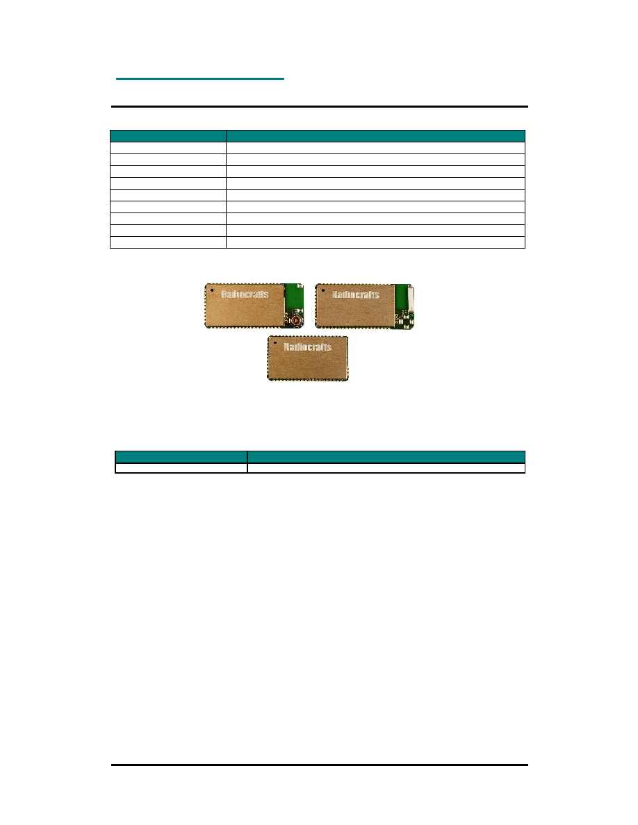
Ordering Information
Ordering Part Number Description
RC2200AT
ZigBee-ready RF module, 128 kB Flash, integrated antenna
RC2200MM
ZigBee-ready RF module, 128 kB Flash, MMCX connector
RC2200
ZigBee-ready RF module, 128 kB Flash (no antenna/connector)
RC2204AT
ZigBee-ready RF module, 64 kB Flash, integrated antenna
RC2204MM
ZigBee-ready RF module, 64 kB Flash, MMCX connector
RC2204
ZigBee-ready RF module, 64 kB Flash (no antenna/connector)
RC2202AT
ZigBee-ready RF module, 32 kB Flash, integrated antenna
RC2202MM
ZigBee-ready RF module, 32 kB Flash, MMCX connector
RC2202
ZigBee-ready RF module, 32 kB Flash (no antenna/connector)
RC220xMM
RC220xAT
RC220x
Document Revision History
Document Revision
Changes
1.0
First release

RC220x
©
2005 Radiocrafts AS
RC220x Data Sheet (rev. 1.0)
Page 17 of 17
Product Status Definitions
Data Sheet Identification
Product Status
Definition
Preliminary
Engineering Samples
and First Production
This data sheet contains preliminary data, and
supplementary data will be published at a later date.
Radiocrafts reserves the right to make changes at
any time without notice in order to improve design
and supply the best possible product.
Disclaimer
Radiocrafts AS believes the information contained herein is correct and accurate at the time of this printing. However,
Radiocrafts AS reserves the right to make changes to this product without notice. Radiocrafts AS does not assume
any responsibility for the use of the described product; neither does it convey any license under its patent rights, or
the rights of others. The latest updates are available at the Radiocrafts website or by contacting Radiocrafts directly.
As far as possible, major changes of product specifications and functionality, will be stated in product specific Errata
Notes published at the Radiocrafts website. Customers are encouraged to check regularly for the most recent
updates on products and support tools.
Trademarks
ZigBee is a trademark of the ZigBee Alliance. All other trademarks, registered trademarks and product names are the
sole property of their respective owners.
Life Support Policy
This Radiocrafts product is not designed for use in life support appliances, devices, or other systems where
malfunction can reasonably be expected to result in significant personal injury to the user, or as a critical component
in any life support device or system whose failure to perform can be reasonably expected to cause the failure of the
life support device or system, or to affect its safety or effectiveness. Radiocrafts AS customers using or selling these
products for use in such applications do so at their own risk and agree to fully indemnify Radiocrafts AS for any
damages resulting from any improper use or sale.
© 2005, Radiocrafts AS. All rights reserved.
Contact Information
Web site: www.radiocrafts.com
Email:
radiocrafts@radiocrafts.com
Address:
Radiocrafts AS
Gunnar Schjelderups vei 11
NO-0485 OSLO
NORWAY
Tel: +47 970 86 676
Fax: +47 22 71 29 15
E-mail:
sales@radiocrafts.com