∑ Compact for High
Density PCB M ount
∑ Small Footprint
∑ UL, CSA, VDE Approved
These solid state relays combine small
size and high ratings in a PC-board-
mounted SPST-NO design. Available
with (S30 types) or without snubber net-
FastFax Document No. 117
SERIES 3
Rev. 042302
PAGE 1 OF 1
Series 3
3 Amp ∑ 120, 240 Vac ∑ AC Output
work (S3 types), Series 3 is an ideal
replacement for power reed relays in
microprocessor or computer-based logic
level systems. Designed for long, reli-
able service in a multitude of demand-
ing industrial environments.
Manufactured in Crydom's ISO 9001
Certified facility for optimum product
performance and reliability.
M O D E L N O .
S312
S3012A
S322
S3022A
INPUT SPECIFICATIONS
Control Voltage Range
3.5-8 Vdc
3.5-8 Vdc
Nominal Input Impedance
200 Ohm
200 Ohm
Typical Input Current @ 5 Vdc
20 mAdc
20 mAdc
Must Turn On Voltage
3.5 Vdc
3.5 Vdc
Must Turn Off Voltage
1.0 Vdc
1.0 Vdc
OUTPUT SPECIFICATIONS
Operating Voltage Range (47-63 Hz)
20-140 Vrms
40-280 Vrms
Load Current Range (Arms)
.15-3.0
.15-3.0
.15-3.0
.15-3.0
Transient Over-Voltage
600 Vpk
600 Vpk
Max. Surge Current, (16.6ms)
55 Apk
55 Apk
Min. Off-State dv/dt @ Max. Rated Voltage
200 V/µsec
200 V/µsec
Max.Off-State Leakage @ Rated Voltage
1.0 mA
4.0 mA
1.0 mA
4.0 mA
Max. On-State Voltage Drop @ Rated Current
1.5 Vpk
1.5 Vpk
Max.Turn-On Time
1/2 cycle
1/2 cycle
Max. Turn-Off TIme
1/2 cycle
1/2 cycle
Power Factor (Min.) WIth Max. Load
0.5
0.5
GENERAL SPECIFICATIONS
Dielectric Strength
4000 Vrms
Insulation Resistance (Min.) @ 500 Vdc
10
9
Ohm
Max. Capacitance
8.0 pF
A
mbient Operating Temperature Range
-30 to 80∞C
Ambient Storage Temperature Range
-30 to 125∞C
M ECHANICAL SPECIFICATIONS
Weight: (typical)
0.6 oz. (0.8 g)
Encapsulation:
Thermally Conductive Epoxy
G E N E R A L N O T E S
All parameters at 25∞C unless otherwise specified.
Dielectric and insulation resistance are measured between input and output.
Off-State dv/dt test method per EIA/NARM standard RS-443.
1.45
(36.8)
.70
(17.8)
1.20
(30.5)
S3
Package
S30
Package
.025 x .025
TERMINAL PIN
(4 PLACES)
.025 x .025
TERMINAL PIN
(4 PLACES)
.70
(17.8)
.80
(20.3)
.45
(11.4)
.68
(17.3)
.60
(15.2)
.80
(20.3)
.10
(2.5)
.70
(17.8)
.87
(22.1)
.60
(15.2)
.80
(20.3)
.10
(2.5)
.80
(20.3)
L
OAD
IN
P
U
T
1
2
3
4
L
OAD
IN
P
U
T
1
2
3
4
BOTTOM
VIEW
BOTTOM
VIEW
+
+
APPROVALS
UL
E116949
CSA
LR81689
VDE 10114 UG
4
3
2
1
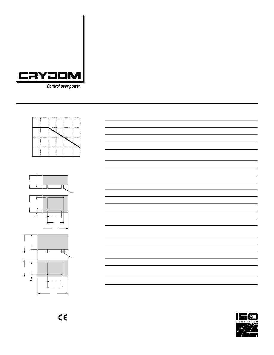
0
20
40
80
60
Ambient Temperature [∞˚C]
Load Current [Amps]
Max Load Current vs. Temperature
CURRENT DERATING CURVE
©2002 CRYDOM CORP, Specifications subject to change without notice.
All dimensions are in inches (millimeters)
For recommended applications and more information contact:
USA: Sales Support (877) 502-5500 Tech Support (877) 702-7700 FAX (619) 710-8540
Crydom Corp, 2320 Paseo de las Americas, Ste. 201, San Diego, CA 92154
Email: sales@crydom.com WEB SITE: http://www.crydom.com
UK: +44 (0)1202 365070 ∑ FAX +44 (0)1202 365090 Crydom International Ltd., 7 Cobham
Road, Ferndown Industrial Estate, Ferndown, Dorset BH21 7PE, Email: intsales@crydom.com.
GERMANY: +49 (0)180 3000 506