SDR2207 Series - SMD Power Inductors
Features
Available in E12 series
Low height of only 7.0 mm
Inductance as low as 0.8 µH
High current up to 16 amps
Lead free version available (see How to
Order)
Lead free versions are RoHS compliant*
Applications
Input/output of DC/DC converters
Power supplies for:
· Portable communications equipment
· Camcorders
· LCD TVs
· Car radios
Electrical Specifications
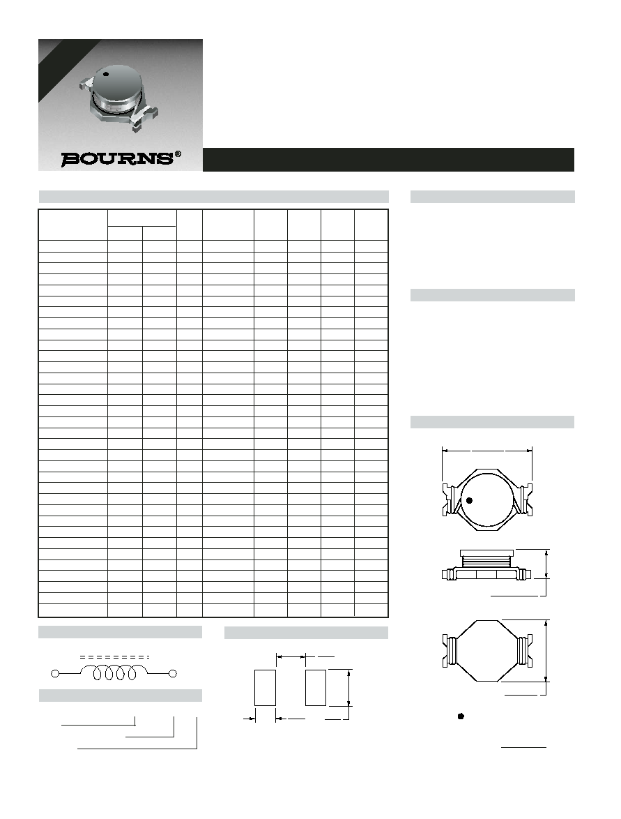
Product Dimensions
Recommended Layout
General Specifications
Test Voltage .....................................0.1 V
Reflow Soldering....230 °C; 10 sec. max.
Operating Temperature ..-40 °C to +125 °C
(Temperature rise included)
Storage Temperature
.................................-40 °C to +125 °C
Resistance to Soldering Heat
................................230 °C for 10 sec.
Materials
Core.........................................Ferrite DR
Wire .............................Enameled copper
Terminal Electrode ......See How to Order
Base................................Phenolic T375J
Adhesive ..............................Epoxy resin
Rated Current
....................Ind. drop 10 % typ. at Isat
Temperature Rise
.......................40 °C max. at rated Irms
Packaging ....................250 pcs. per reel
22.0 ± 0.3
(.866 ± .012)
= START OF WINDING
7.0 + 0.8/-0.4
(.276 + .031/-.016)
15.0 ± 0.3
(.591 ± .012)
4.0
(.157)
13.5
(.531)
9.0
(.354)
Electrical Schematic
Inductance 100 KHz
Q
Test
SRF
RDC
I rms
I sat
Bourns Part No.
(
µ
µH)
Tol. %
Ref.
Frequency
Min.
(m
)
Max.
Typ.
(MHz)
(MHz)
(A)
(A)
SDR2207-R80M_
0.8
± 20
30
5
102.0
2.8
16.0
35.0
SDR2207-1R2M_
1.2
± 20
30
3
70.0
3.8
15.0
30.0
SDR2207-1R8M_
1.8
± 20
31
3
51.0
4.5
13.0
25.0
SDR2207-2R7M_
2.7
± 20
38
3
51.0
7.0
10.0
20.0
SDR2207-3R3M_
3.3
± 20
38
3
39.0
7.8
9.0
17.0
SDR2207-4R7M_
4.7
± 20
38
3
33.0
8.8
8.5
15.0
SDR2207-5R6M_
5.6
± 20
50
3
30.0
13.4
7.8
14.0
SDR2207-6R8M_
6.8
± 20
38
3
27.0
14.2
7.5
12.0
SDR2207-8R2M_
8.2
± 20
35
3
25.0
15.5
7.0
11.0
SDR2207-100M_
10
± 20
53
5
20.0
17.2
6.5
10.0
SDR2207-120Y_
12
± 15
50
5
19.0
23.6
5.5
9.5
SDR2207-150Y_
15
± 15
38
5
16.0
28.8
5.0
9.0
SDR2207-180Y_
18
± 15
46
5
15.0
33.0
4.6
8.0
SDR2207-220Y_
22
± 15
27
3
14.0
39.4
4.0
6.5
SDR2207-270Y_
27
± 15
22
3
12.0
43.5
3.8
6.0
SDR2207-330Y_
33
± 15
27
3
11.0
58.4
3.4
5.5
SDR2207-390K_
39
± 10
18
3
10.0
65.0
3.2
5.2
SDR2207-470K_
47
± 10
27
3
9.0
91.2
2.8
5.0
SDR2207-560K_
56
± 10
25
2
8.3
96.5
2.6
4.5
SDR2207-680K_
68
± 10
18
2
7.9
112.0
2.4
4.0
SDR2207-820K_
82
± 10
28
2
6.5
144.0
2.3
3.5
SDR2207-101K_
100
± 10
18
2
6.2
168.0
2.2
3.0
SDR2207-121K_
120
± 10
20
2
6.0
230.0
1.6
3.0
SDR2207-151K_
150
± 10
22
2
5.8
250.0
1.5
2.6
SDR2207-181K_
180
± 10
20
2
5.7
300.0
1.3
2.5
SDR2207-221K_
220
± 10
19
2
5.5
380.0
1.2
2.4
SDR2207-271K_
270
± 10
17
2
5.3
470.0
1.1
2.2
SDR2207-331K_
330
± 10
20
1
5.1
560.0
1.0
1.9
SDR2207-391K_
390
± 10
17
1
4.9
680.0
0.9
1.7
SDR2207-471K_
470
± 10
19
1
4.7
850.0
0.8
1.4
SDR2207-561K_
560
± 10
18
1
4.5
1000
0.8
1.3
SDR2207-681K_
680
± 10
16
1
4.2
1100
0.7
1.2
SDR2207-821K_
820
± 10
16
1
3.9
1400
0.6
1.1
SDR2207-102K_
1000
± 10
15
1
3.5
1800
0.6
1.0
DIMENSIONS:
MM
(INCHES)
LEAD FREE
VERSIONS ARE
RoHS COMPLIANT
*RoHS Directive 2002/95/EC Jan 27 2003 including Annex
Specifications are subject to change without notice.
Customers should verify actual device performance in their specific applications.
How to Order
SDR2207 - 100M __
Model
Value/Tolerance: from table
Termination
L = Cu/Sn
Blank = Cu/SnPb
34.0
(1.34)
38.4
(1.51)
2.0 ± 0.5
(.079 ± .020)
50.0
(1.969)
330
(12.99)
DIA.
13.0 ± 0.5
(.512 ± .020)
DIA.
13.0 ± 0.5
(.512 ± .020)
DIA.
21.0 ± 0.8
(.827 ± .031)
EMBOSSED
CARRIER
EMBOSSED
CAVITY
0.10
(.004)
THICKNESS
MAX.
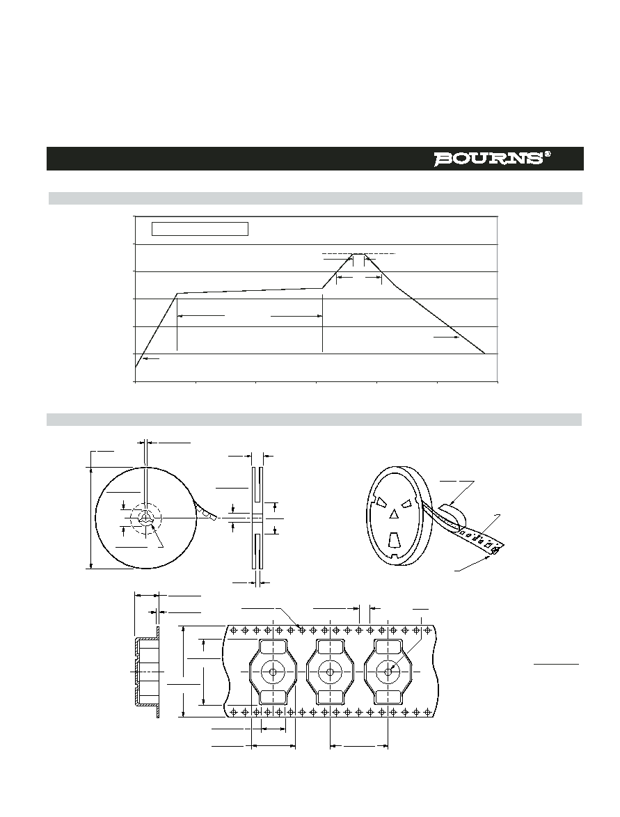
Packaging Specifications
22.4 ± 0.1
(.882 ± .004)
32.0 ± 0.3
(1.26 ± .012)
9.0 ± 0.1
(.354 ± .004)
15.5 ± 0.1
(.610 ± .004)
20.0 ± 0.1
(.787 ± .004)
4.0 ± 0.1
(.157 ± .004)
1.55 ± 0.05
(.061 ± .002)
2.0
(.079)
MIN.
8.45 ± 0.1
(.333 ± .004)
0.5 ± 0.05
(.020 ± .002)
QTY: 250 PCS. PER REEL
SDR2207 Series - SMD Power Inductors
DIMENSIONS:
MM
(INCHES)
REV. 02/05
Specifications are subject to change without notice.
Customers should verify actual device performance in their specific applications.
Soldering Profile
0
50
100
150
200
250
300
0
50
100
150
200
250
300
Time (seconds)
Temperature (°C)
<1> Max. of 30 seconds > 200 °C
<2> Max. of 10 seconds at 230 °C
230 °C
<2>
<1>
120 - 150 seconds
Ramp-up
4 °/second maximum
Ramp-down
5 °C/second maximum