Semelab Plc. reserve the right to change the products shown on this datasheet in the interest of improved specification. No responsibility is assumed for
the use of information contained herein, nor for any infringement of patent or rights of others that may result from such use. No license is granted by
implication or otherwise under any patent or patent right of Semelab Plc.
SDV1015-300: 300W RMS, CLASS D,
AUDIO AMPLIFIER MODULE
FEATURES
∑ HIGH POWER: 300W RMS
1
∑ HIGH EFFICIENCY >90%
∑ HIGH SWITCHING FREQUENCY: 450KHz.
∑ LOW DISTORTION: <0.2% THD OPEN LOOP
∑ SIMPLE POWER SUPPLY REQUIREMENT
2
∑ THERMALLY EFFICIENT PACKAGE:
-INTEGRAL HEATSINK
-NO COOLING FANS REQUIRED
∑ LOW NOISE: NOISE FLOOR typ. 85dB DOWN
3
∑ EMC SCREEN INTEGRAL TO PACKAGE
∑ OVER TEMPERATURE PROTECTION OPTION
4
∑ LOW QUIESCENT CURRENT - MUTE FACILITY
∑ DRIVES A 16
, 8
AND 4
SPEAKER
5
∑ SLAVE MODULES CAN BE LINKED TO BOOST
DRIVE CAPABILITY (WITH MASTER OPTION)
∑ OTHER POWER OPTIONS AVAILABLE
1
∑ LOW COST
∑ LIGHTWEIGHT
∑ CUSTOM AMPLIFIER DESIGNS AVAILABLE
NOTES
1) Other power options include 1000W, 800W, 600W, 150W and
50W. Alternately, custom power levels can be produced.
2) Companion PSU unit will be available 2001
3) Assumes minimisation of external noise coupling and measured
in audio band only.
4) Contact Magnatec Ltd. for more details of these options
5) 2
speaker variant available
APPLICATIONS
∑ PROFESSIONAL AUDIO POWER AMPLIFIER
∑ ACTIVE SPEAKER SYSTEMS
∑ ACTIVE SONAR SYSTEMS
∑ NOISE CANCELLATION SYSTEMS
∑ MOTOR / MAGNET DRIVE MODULES
∑ POWER CONVERSION
∑ UPS - SINE WAVE INVERTER
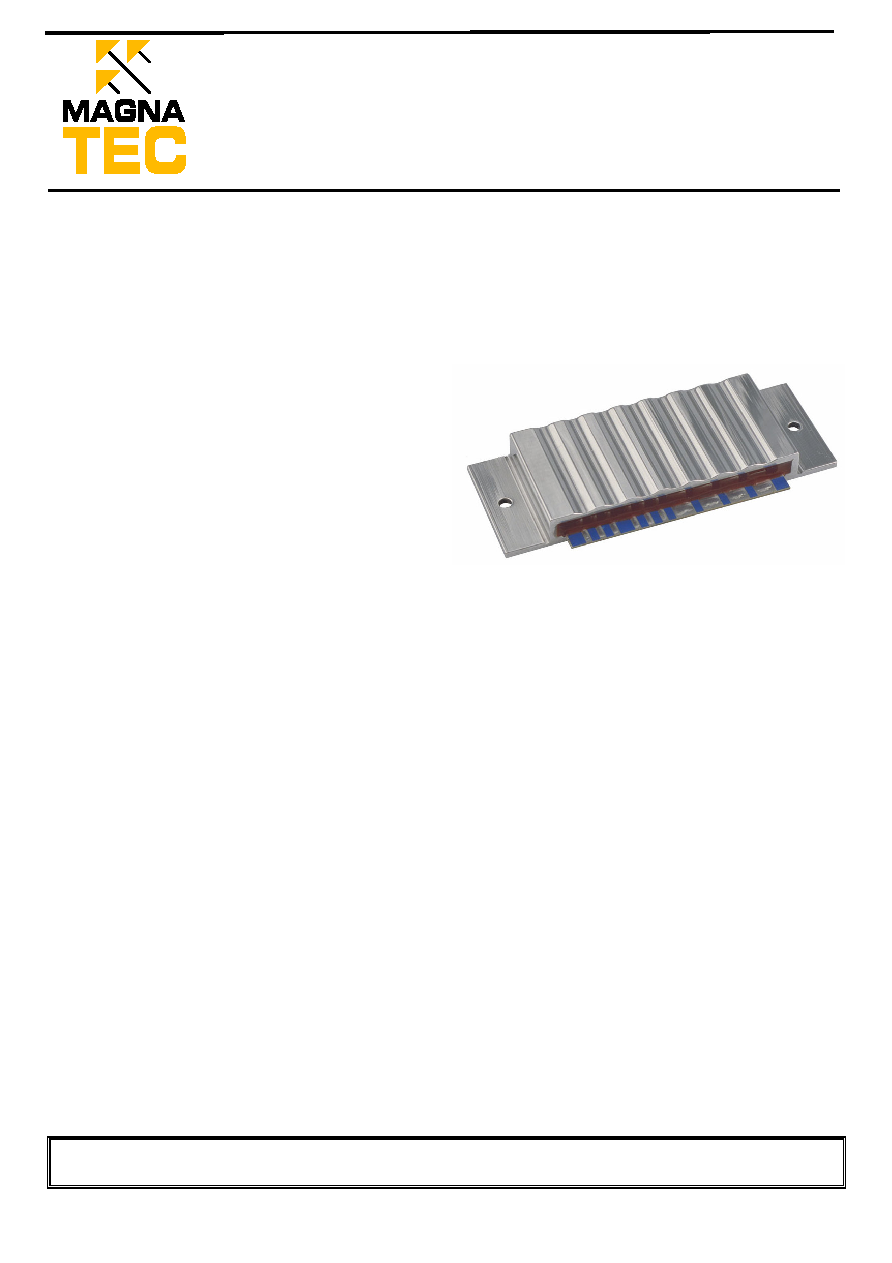
DESCRIPTION
The SDV1015-300 is a complete professional audio
power amplifier module. The module contains power
transistors, drive electronics and control circuitry. Only a
power supply, decoupling capacitors and output filter must
be added to produce a stand-alone professional audio
amplifier. Modules can be ganged together and operated
from a single power supply to produce a stereo amplifier.
The module is optimised to drive a 4
load (16, 8 and
2
optimised versions are available). For higher power
applications consider the 600W rms module (SDV1015-
600).
Please contact Magnatec Ltd. for a confidential discussion of
your requirements and further application information.
CLASS D AUDIO AMPLIFIER MODULE

Semelab Plc. reserve the right to change the products shown on this datasheet in the interest of improved specification. No responsibility is assumed for
the use of information contained herein, nor for any infringement of patent or rights of others that may result from such use. No license is granted by
implication or otherwise under any patent or patent right of Semelab Plc.
Rail voltage, V
RS
....................................................................................... 60 V
Control voltages +V
L
................................................................................. +18 V
Control voltages -V
L
................................................................................. -14 V
Operating free air temperature, T
A
......................................................... -10
∞C to 40∞C
Storage temperature range, T
stg
.............................................................. -40
∞C to 70∞C
PCB solder pad temperature for 60 secs ............................................................. 260
∞C
Stresses beyond those listed under absolute maximum ratings may cause permanent damage to the device. These are stress ratings only and functional operation
of the device at these or any other conditions beyond those indicated "recommended operating conditions" is not implied.
Recommended operating conditions
MIN
TYP
MAX
UNIT
RAIL VOLTAGE, V
RS
0
49
55
V
POWER SUPPLY VOLTAGES, +V
L
10
12
15
V
POWER SUPPLY VOLTAGES, -V
L
-7
-8
-12
V
AUDIO INPUT, S
2
0
+1
+1.09
Vp-p
MODULATION FACTOR
0
0.9
0.98
OPERATING FREE AIR TEMPERATURE, T
A
10
60
∞C
Electrical characteristics at a free air temperature of 25∞∞∞∞C
VALUE
PARAMETER
NOTES/TEST CONDITIONS
V
RS
= 50 V
UNIT
MIN
TYP
MAX
S
3
ENABLE INPUT
(Other input options available)
LEAVE UNCONNECTED OR
CONNECT TO 0V TO ENABLE
4.75
5
5.25
Vp-p
R
EN
ENABLE INPUT IMPEDANCE
10
K
R
IN
AUDIO INPUT IMPEDANCE
(Other input options available)
7.3
K
I
L+
POWER SUPPLY CURRENT +V
L
R
L
= 4
100
150
mA
I
L-
POWER SUPPLY CURRENT -V
L
R
L
= 4
30
50
mA
I
RS
POWER RAIL CURRENT
R
L
= 4
6
A
P
RR
ALLOWABLE POWER RAIL
RIPPLE
SEPARATE POWER SUPPLY
MODULE AVAILABLE
2
%
r
O
OUTPUT RESISTANCE
R
L
= 4
100
m
SNR
SIGNAL TO NOISE RATIO
R
L
= 4
(in audio band)
-85
dB
f
SW
SWITCHING FREQUENCY
(Provisional)
450
KHz
t
PD
PROPAGATION DELAY
(POWER OUTPUT STAGE)
R
L
= 4
150
ns
SPECIFICATIONS
Absolute maximum ratings

Semelab Plc. reserve the right to change the products shown on this datasheet in the interest of improved specification. No responsibility is assumed for
the use of information contained herein, nor for any infringement of patent or rights of others that may result from such use. No license is granted by
implication or otherwise under any patent or patent right of Semelab Plc.
Rail voltage versus maximum power into
a pure 4 ohm pure resistive load
0
10
20
30
40
50
60
0
50
100
150
200
250
300
350
400
Power (W)
R
a
i
l
v
o
l
t
a
g
e
(
V
)
The total coupled power from the input of the amplifier to the load is determined by three parameters.
These are:
1.
The input signal level with respect to the maximum input level (Modulation factor)
2.
The Inherent efficiency of the amplifier module.
3.
The attenuation of the audio signal by the output filter (Filter attenuation).
Modulation Factor
The maximum input audio signal level for the amplifier is normally +1.1V peak to peak. For signal
levels greater than this range the amplifier will 'clip', which will produce a distorted signal. Driving the
amplifier into clip will not damage the module but will severely degrade the replication of the audio
signal and can in some cases damage the loudspeakers. At + 1V peak to peak the modulation factor is 0.9
i.e. the input signal is at 90% of the full input range. If the input signal magnitude is well controlled,
higher modulation factors can be used. In practice 0.98 modulation factor (+1.09V peak to peak) should
be considered the absolute maximum and 0.95 (+1.05V peak to peak) should be adopted in applications
where maximum power coupled to the loudspeaker load is desirable. If the amplifier module is to be used
at high modulation factors we recommend using an anti-clip circuit. This circuitry can either be added by
the user external to the module or selected anti-clip options can be incorporated into the package. For the
various options, please see the later section or contact Magnatec Ltd.
Inherent Efficiency
The amplifier modules are tested for the inherent
efficiency by measuring the power coupled into the
defined load (non-inductive dummy load). To calculate
the inherent efficiency, the differential voltage across
the load is measured for the defined rail voltage. The
control of the power output from the amplifier module
is achieved by varying the rail voltage. At a given rail
voltage the maximum theoretical output power is
given by the chart opposite.
For example, if the rail voltage is 20V and the
differential voltage across the load is measured at 38V,
the power into a 4
load would be:
OUTPUT POWER and EFFICIENCY
Total coupled power
Measured power = (38/2)
2
/(4 * 2) or 45Wrms
From the chart above:

Semelab Plc. reserve the right to change the products shown on this datasheet in the interest of improved specification. No responsibility is assumed for
the use of information contained herein, nor for any infringement of patent or rights of others that may result from such use. No license is granted by
implication or otherwise under any patent or patent right of Semelab Plc.
Maximum theoretical output power at 20V = 50Wrms.
Then, the Inherent Efficiency of the amplifier module is 90%.
In practice, the quality of the amplifier terminations can affect the Inherent
Efficiency, for maximum efficiency, the power connections (Rail voltage, Output
terminals and the power ground) should be made with soldered connections. If
losses in the wiring to the load are minimised Inherent Efficiencies of 95% are achievable.
Filter Attenuation
The direct output from the amplifier module is a
pulse width modulated signal. The underlying audio
signal has been mixed inside the amplifier with a
switching frequency at 450KHz. It is possible to
connect the amplifier output directly to a loudspeaker
and produce acceptable performance. However, if the
speaker is remote from the amplifier or sensitive high
frequency tweeters are being used it is advisable to
filter out the switching frequency.
Design of a high efficiency, flat passband filter
with maximum attenuation of the switching frequency
is not trivial. Hence, the audio amplifier output filter
requirements are minimum attenuation and distortion
in the passband from 20Hz to 20KHz and maximum
attenuation at the switching frequency. The load for the
filter is a 4
loudspeaker which could vary
dynamically from 1
to 8. If a simple LC lowpass
filter is used to minimise the attenuation in the audio
band of frequencies, the attenuation of the modulation
fundamental frequency will be typically 25dB. In
addition, any gain peaking introduced by the simple
filter will distort the upper frequency ranges of the
audio band and introduce instabilities. In some
applications this simple filter could be acceptable.
However, for more demanding applications, Magnatec
Ltd have developed and patented a filter for use with
the amplifier that provides greater than 40dB
attenuation of the switching frequency, whilst
providing a flat audio passband with less than 0.5dB
attenuation. For more details of alternative filter
combinations contact Magnatec Ltd.
When calculating the total coupled power, the combined effects of the above parameters must be
considered. One final parameter that will affect the total coupled power that is within the control of the user
is the wiring resistance. It is important to minimise the resistance of the cableforms from the amplifier to the
filter (if used) and from the filter to the loudspeaker. For example, 0.1
of cable resistance will form a
potential divider with the speaker load. For a 4
load the power loss due to this wiring resistance is 0.4dB.
Simple LC filter with gain peak
-60.00
-50.00
-40.00
-30.00
-20.00
-10.00
0.00
10.00
20.00
30.00
1,000
10,000
100,000
1,000,000
Frequency (Hz)
T
r
a
n
s
m
i
s
s
i
o
n
(
d
B
)
L
C
L
C
SDV1015-600
POWER AMPLIFIER
MODULE
OUT1
OUT2

Semelab Plc. reserve the right to change the products shown on this datasheet in the interest of improved specification. No responsibility is assumed for
the use of information contained herein, nor for any infringement of patent or rights of others that may result from such use. No license is granted by
implication or otherwise under any patent or patent right of Semelab Plc.
If the total coupled power into the load is expressed in decibels of loss
(excluding wiring resistance) then:
Total coupled power = theoretic output power + modulation factor + inherent
efficiency + Filter attenuation
Using our patented filter design, and maximum modulation factor, it is possible to
achieve total coupled power figures of 90% or -0.5dB attenuation in the audio pass band.
To minimise quiescent power dissipation the output power stage of the module can be disabled using the enable
(S3) input.
DISTORTION and NOISE
The noise characteristics of the SDV1015-300 amplifier module are different from a linear amplifier in
that the dominant source of 'noise' is the amplifier switching frequency. This frequency at 450KHz is
present even when no audio signal is input to the amplifier. The switching signal is a square wave and will
have harmonics of the fundamental frequency e.g. 1.350MHz, 2.25MHz, 3.15MHz etc. The output filter if
used, must attenuate this signal and let the audio signal through without attenuation or distortion. Semelab
plc. have applied for a patent on a new filter configuration that is able to effectively attenuate the
switching signal and leave the audio signal unaffected.
Using our proprietary filter technology it is possible to attenuate the fundamental of the switching
frequency by about 40dB. This filter produces a flat audio passband, irrespective of variations in the
loudspeaker load, with 5% power loss in the audio passband. Greater attenuation of the switching frequency
can be achieved if more attenuation in the audio band is permitted. Magnatec is able to supply filters
designed to a custom requirement.
To minimise external interference signals, the audio connection to the amplifier should be via a low noise
screened cable. The amplifier module should not be positioned directly adjacent to mains or similar high
level voltages. The power supply used to supply the rail voltage should be regulated with a minimum ripple
level of 1% or less.