 | –≠–ª–µ–∫—Ç—Ä–æ–Ω–Ω—ã–π –∫–æ–º–ø–æ–Ω–µ–Ω—Ç: TCA440T | –°–∫–∞—á–∞—Ç—å:  PDF PDF  ZIP ZIP |
AM - Receiver Circuit
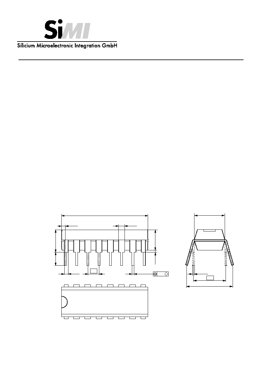
Package
Technical Data
TCA 440 / T
Edition 12/95
5.1
19.4
±
0.2
0.47
±
0.12
0.51
1.40
2.50
1.27
3.5
16
15
14
13
12
11
10
1
2
3
4
5
6
7
8
9
0.25
M
0.27
+0.09
-0.07
7.55
6.4
+0.2
- 0.1
7.9 . . . 9.7
+1.0
- 0.5
0.98
3.6
+0.2
-
0.1
12/95
1
TCA 440 ∑ DIP 16
Description
This is an efficient bipolar monolithic circuit to apply
in battery - powered or mains - operated radio
receivers up to 30 MHz. It contains controlled RF
stage, mixer, separated oscillator and regulated
multistage IF amplifier.
Features
∑ symmetrical structured circuitry
∑ controlled RF prestage
∑ multiplicative balanced mixer, separated oscillator
∑ very well implemented large - signal characteristic
begins already from 4.5 V supply voltage
∑ terminals for indicating instrument
∑ controlled IF amplifier implementing 60 dB control
range
∑ external demodulator (diode)
∑ wide range of supply voltage between 4.5 and 15 V

Pin configuration
1
RF prestage, input 1
9
input IF control amplifier
2
RF prestage, input 2
10
indicator output IF control amplifier
3
RF control amplifier input
11
IF blocking
4
oscillator circuit pin 1
12
input lF amplifier
5
oscillator circuit pin 2
13
IF blocking
6
oscillator circuit pin 3
14
supply voltage
7
IF output
15
mixer output 1
8
ground
16
mixer output 2
Block diagram
OSCILLATOR
V
CC
6
MIXER
PRE-
STAGE
STABILISATION
1
st
IF
STAGE
2
nd
IF
STAGE
3
rd
IF
STAGE
4
th
IF
STAGE
IF GAIN
CONTROL
IF FILTER
5
4
8
15
12
11
13
10
9
7
14
16
3
1
2
HF - CIRCUIT
V
CC
TUNING
INDICATOR
AF
3.5V
3.5V
V
CC
IF REQUIRED
5
6
7
8
3
4
1
2
9
10
11
12
13
14
15
16
9.9
±
0.1
0.42
1.27
0.7
0...8
∞
0.19 +
0.06
0.3
3.9
±
0.1
6.0
±
0.2
0.25
M
0.15
1.35
±
0.1
0.15
2.00
+ 0.1
-
0.05
+ 0.07
- 0.06
TCA 440 T ∑ SOP 16
2
12/95
TCA 440 / T

Functional description
It contains several function units, which enable designing and assembling of efficient AM tuners. Caused by
internal voltage stabilization characteristics are rather independent from supply voltage.
The RF input signal reaches via a controllable and overdriving proof preselector stage a balanced mixer. By
means of a RF - signal generated by a separated oscillator the input signal is transported into IF. Multiplicative
mixing causes only few harmonic content. Gain control is carried out by means of two separated feedback control
loops for preselector stage and IF amplifier. By these a loop bandwidth of approximately 100 dB is obtained. The
control voltage of the IF - amplifier can be used to drive a moving - coil instrument (field strength indicator). The IF
amplifier consists of 4 amplifier stages, the first, second and third can be controlled. The bandwidth of the IF
amplifier is approximately 2 MHz and on that account sufficient for usual IF frequencies in the AM range of
approximately 460 kHz.
The symmetrical arrangement of the entire circuitry guarantees well oscillating. The bridge of the mixer avoids
direct breakdown.
Absolute maximum ratings
min
max
unit
Supply voltage
V
CC
4.5
15.0
V
Junction temperature
T
j
150
∞C
Ambient operating temperature
T
a
-15
80
∞C
Storage temperature
T
s
-40
125
∞C
Total thermal resistance
R
thja
120
K/W
Recommended operational conditions
min
max
unit
Supply voltage
V
CC
4.5
15
V
Ambient operating temperature
T
a
-10
70
∞C
12/95
3
TCA 440 / T

Characteristics
refer to application examples, f
i
= 1 MHz, f
osc
= 1.455 kHz, f
lF
= 455 kHz, V
CC
= 9 V, f
m
= 1 kHz, m = 0.8,
voltages refer to ground, T
a
= 20 to 25 ∞C, unless specified otherwise
min
typ
max
unit
Current and voltage supply
(no RF signal)
Supply voltage
V
14-8
4.5
9
15
V
Current consumption
V
14-8
= 4.5 V
I
14
7
mA
V
14-8
= 9 V
I
14
10.5
16
mA
V
14-8
= 15 V
I
14
12
mA
Entire receiver
RF level variation
with
V
NF
= 6 dB
V
RF
65
dB
with
V
NF
= 10 dB
V
RF
80
dB
NF output voltages
(symmetrically measured at 1-2)
V
iHF
= 20 µV, m = 0.8
V
NF(rms)
60
140
mV
V
iHF
= 1 mV, m = 0.8
V
NF(rms)
260
mV
V
iHF
= 500 mV, m = 0.8
V
NF(rms)
100
350
560
mV
V
iHF
= 20 µV, m = 0.3
V
NF(rms)
50
mV
V
iHF
= 1 mV, m = 0.3
V
NF(rms)
100
mV
V
iHF
= 500 mV, m = 0.3
V
NF(rms)
130
mV
RF input sensitivity
measured at 60
, m = 0.3,
R
G
= 540
signal-to-noise ratio
S + N/N = 6 dB
V
iRF
1
µV
S + N/N = 26 dB
V
iRF
7
µV
S + N/N = 58 dB
V
iRF
1
mV
Maximum RF input voltage
V
iHF
1.5
V
(THD = 10 %)
Total harmonic distortion
V
HF
= 500 mV
THD
4.5
10
%
V
HF
= 30 mV
THD
2.8
8
%
RF part
Input frequency range
f
iHF
0
50
MHz
Output frequency
f
|F
= f
osc
- f
iHF
f
IF
455
kHz
Control range
G
V
38
dB
4
12/95
TCA 440 / T

min
typ
max
unit
IF suppression
a
lF
20
dB
between 1 - 2 and 15
RF input impedance
unbalanced coupling
V
iHFmax
Z
i
2 II 5
k
IIpF
V
iHFmin
Z
i
2.2 II 1.5
k
IIpF
balanced coupling
V
iHFmax
Z
i
4.5
k
V
iHFmin
Z
i
4.5 II 1.5
k
IIpF
Mixer output impedance
(pin 15 or 16)
Z
o
250 II 4.5
k
IIpF
Steepness
S
HF
28
mS
IF part
Input frequency range
f
ilF
0
2
MHz
Control range
G
V
62
dB
f
ilF
= 455 kHz,
V
NF
= 10 dB
Start of control
V
ctrlF
140
µV
(
V
iIF
/
V
NF
= 10 dB / 3 dB)
maximum IF input voltage
V
ilFmax
200
mV
(THD
NF
= 10 %)
NF output voltage
applied to 60
V
ZF
= 30 µV
V
NF(rms)
50
mV
V
ZF
= 3 mV
V
NF(rms)
200
mV
V
ZF
= 3 mV; m = 0.3
V
NF(rms)
70
mV
IF input impedance
(unbanlanced coupling)
Z
ilF
3 II 3
k
llpF
IF output impedance
Z
O
200 II 8
k
IIpF
(pin 7)
Indication instrument
Recommended indication instruments: 500 µA (R
i
= 800
)
300 µA (R
i
= 1.5 k
)
For indication a voltage source of 600 m V
(EMF)
and an internal source impedance of 400
is available.
12/95
TCA 440 / T
5