WM-C1601M-1TNNC
3/23
Contents Page
(1) Electronic Units ................................................................................................ 4
1.1 Absolute Maximum Ratings
...................................................................................... 4
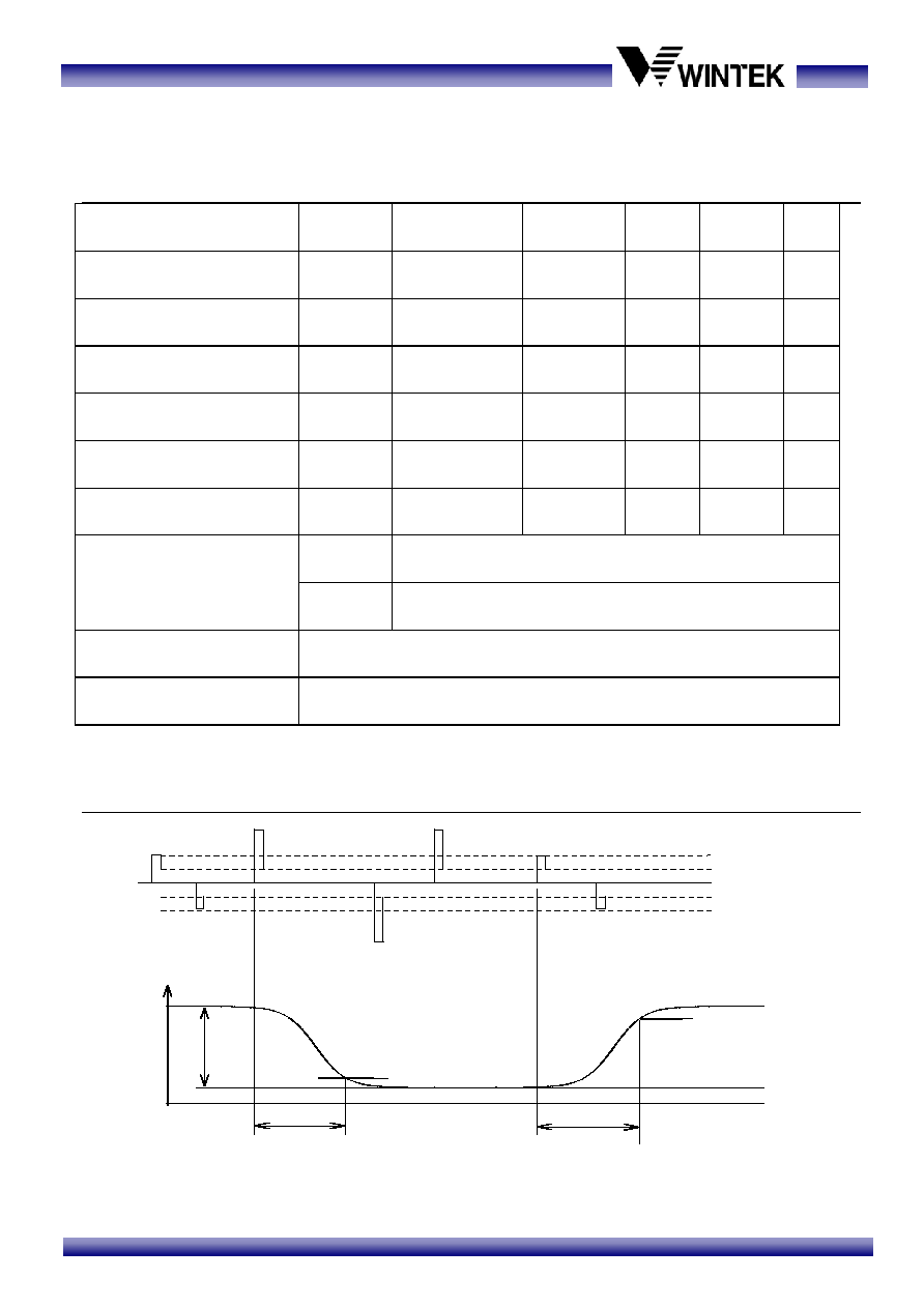
1.2 Electrical Characteristics
.......................................................................................... 4
1.3 Interface Pin Function
................................................................................................ 5
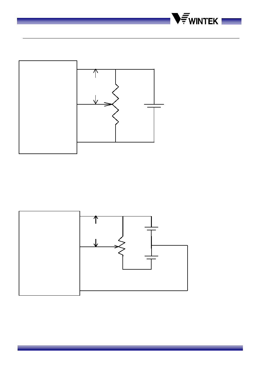
1.4 Power Supply for LCD Module
................................................................................ 6
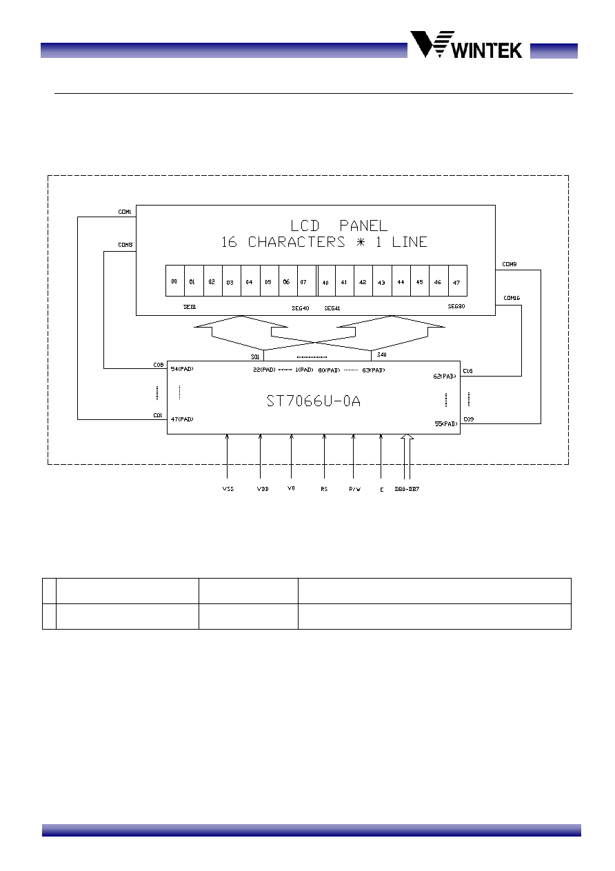
1.5 Block Diagram with Display RAM Address and Initialization Table
................. 7
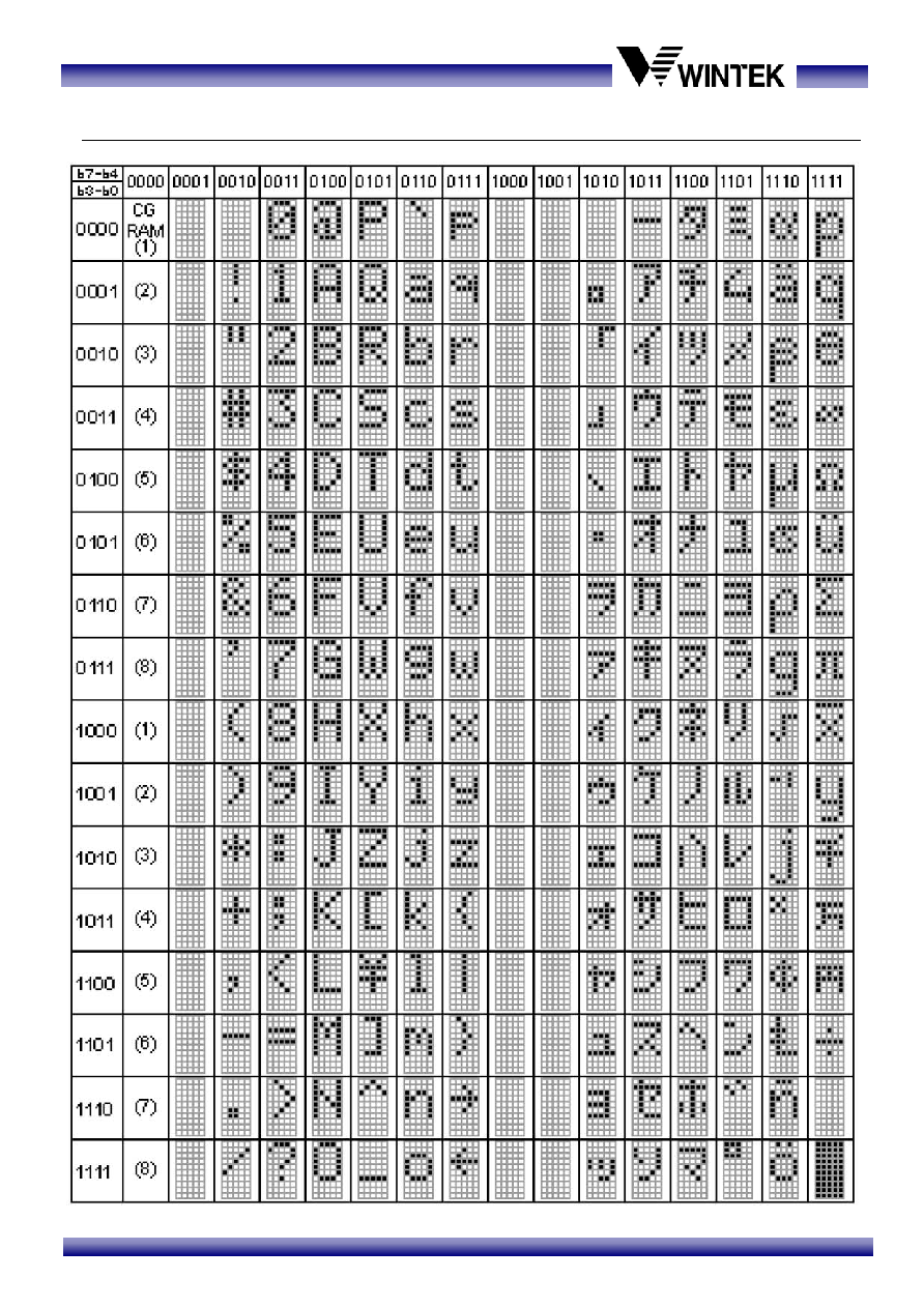
1.6 Character Generator Rom map
............................................................................... 8
(2) Electro-optical Units......................................................................................... 9
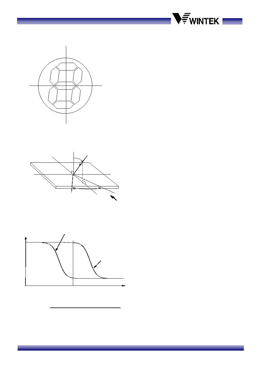
2.1 Electro-optical Characteristics
................................................................................. 9
2.2 Optical Definitions
...................................................................................................... 9
(3) Mechanical Units .............................................................................................11
3.1 Mechanical Specification
........................................................................................ 11
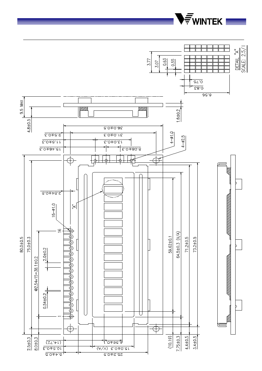
3.2 Mechanical Diagram
................................................................................................ 12
3.3 Packing Method
........................................................................................................ 13
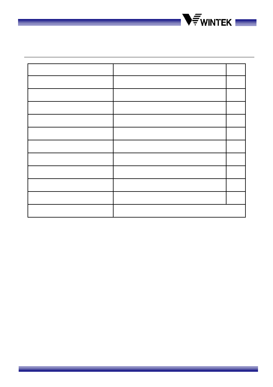
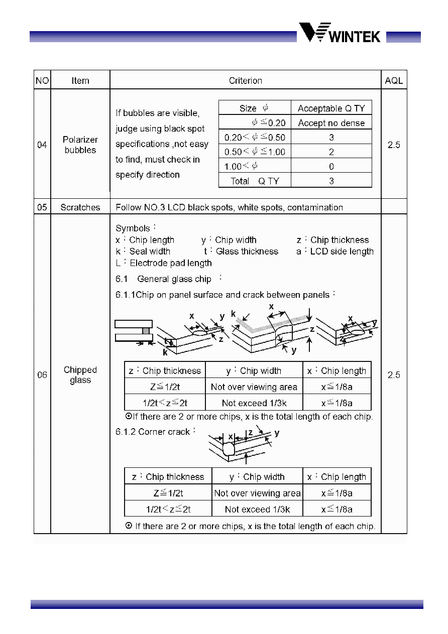
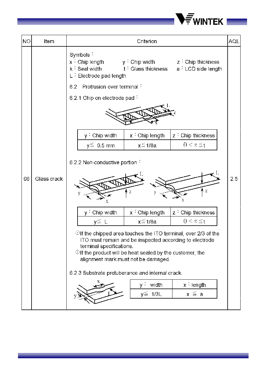
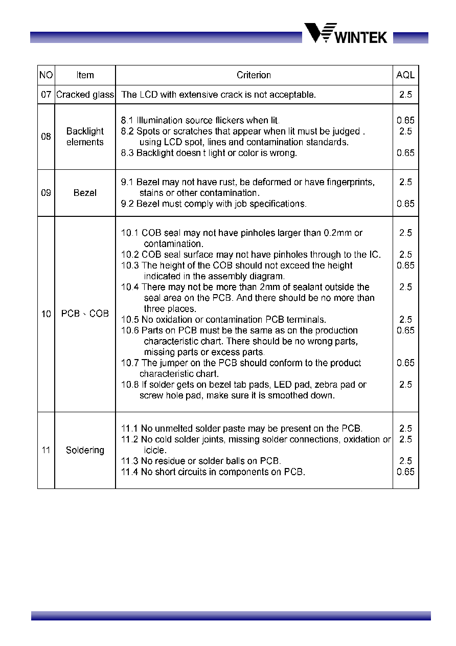
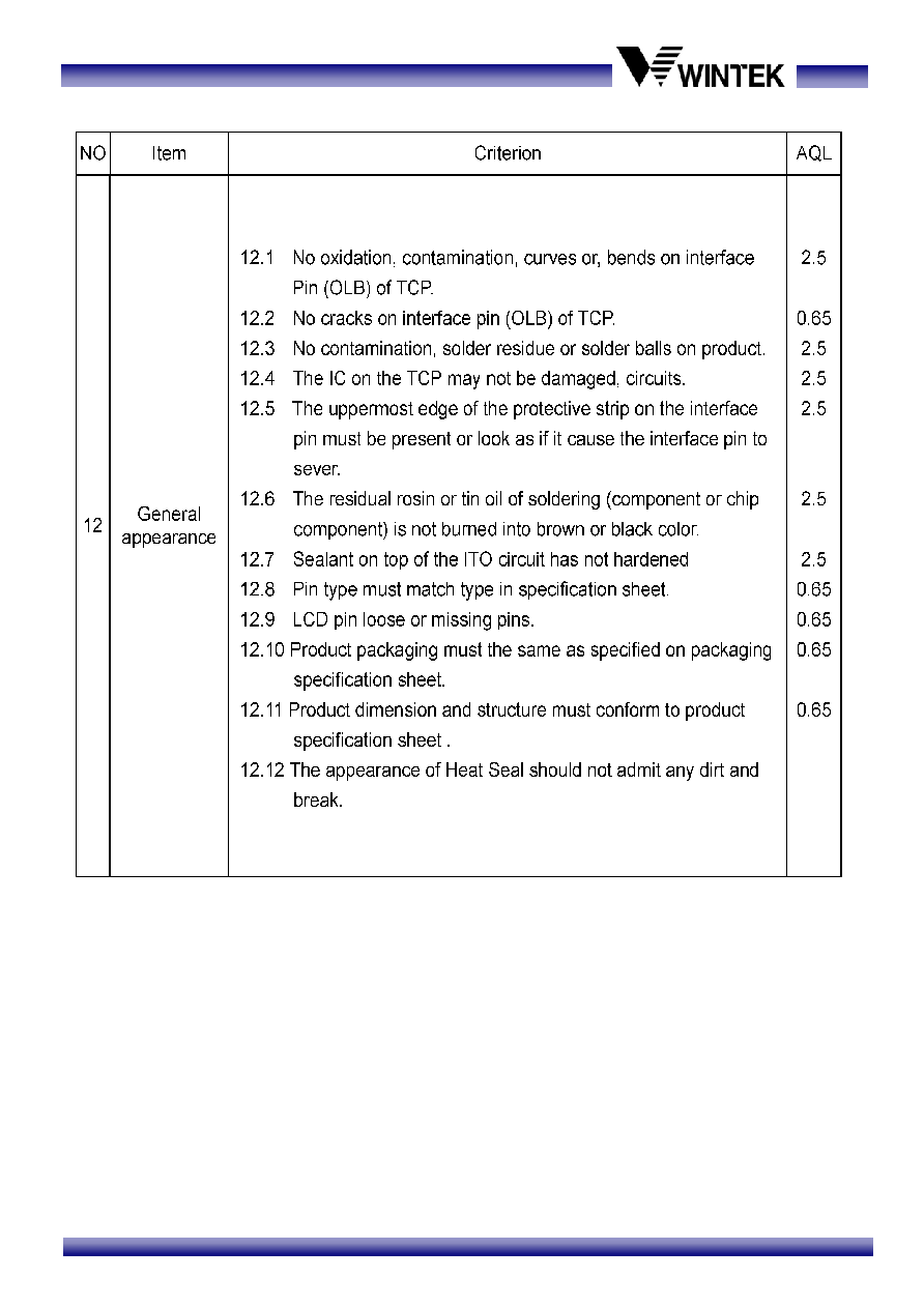
(4) Quality Units ................................................................................................... 14
4.1 Specification of Quality Assurance
....................................................................... 14
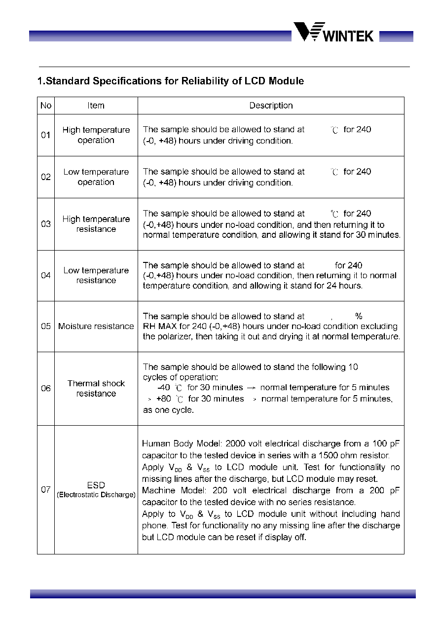
4.2 Standard Specification for Reliability
.................................................................... 21
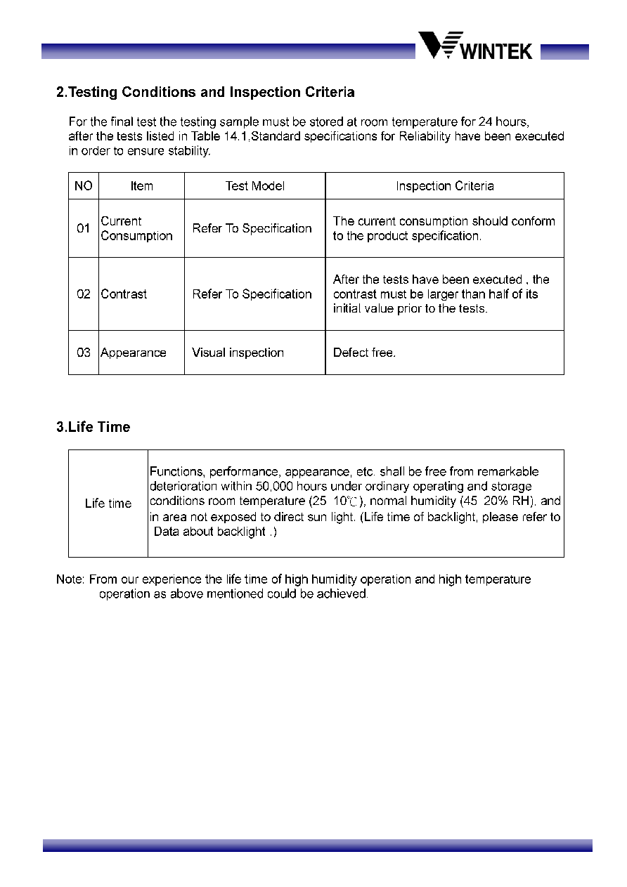
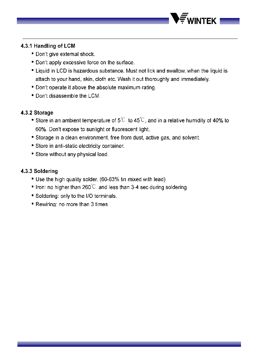
4.3 Precautions in Use of LCM
.................................................................................... 23
Reference Data :
Sitronix ST7066U-0A Specifications
WM-C1601M-1TNNC
4/23
(1) Electronic Units
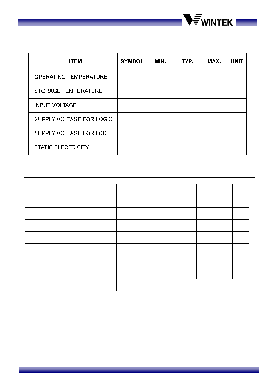
1.1 Absolute Maximum Ratings
1.2 Electrical Characteristics
(VDD=5.0V, Ta=25
°C)
ITEM
SYMBOL CONDITION
MIN. TYP. MAX. UNIT
SUPPLY VOLTAGE FOR LOGIC V
DD
-V
SS
-
4.5 5.0 5.5 V
SUPPLY VOLTAGE FOR LCD
V
DD
-V
0
-
4.3 4.5 4.7 V
INPUT HIGH VOL
V
IH
-
0.7
V
DD
- V
DD
V
INPUT LOW VOL
V
IL
- -
-
0.2
V
DD
V
OUTPUT HIGH VOL
V
OH
I
OH
=-0.04mA 0.9 V
DD
- V
DD
V
OUTPUT LOW VOL.
V
OL
I
OL
= 0.04mA
-
-
0.1 V
DD
V
SUPPLY CURRENT FOR LOGIC
*I
DD
V
DD
=5.0V - 2.5
3.0
mA
USED IC
ST7066U-0A
*I
DD
Measurement condition is for all pixels on display
V
DD
V
0
V
DD
-V
SS
0
-20
-0.3
-0.3
V
DD
10
-
-
-
-
-
+7.0
V
DD
+0.3
+50
+70
V
DD
+0.3
Be sure that you are grounded when handing LCM.
T
OP
T
ST
V
I
°C
°C
V
V
V
WM-C1601M-1TNNC
13/23
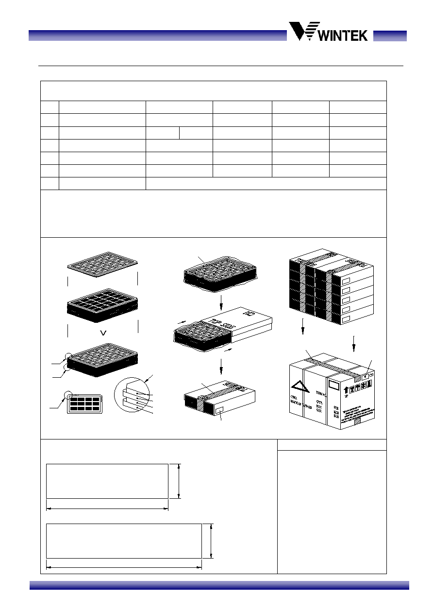
3.3 Packing Method
WM-C1601M-1TNNc
x no per column
x quantity per tray
x quantity per box
(3) Total LCM quantity in carton : no of boxes
Remark
Total Weight
Product Box
Packaging Material : (per carton)
Packaging Specifications and Quantity :
(1) LCM quantity per tray : no per row
(2) LCM quantity per box : no of trays
2.
1.
5
NO
2
3
4
1
Carton
Tray
LCM Module
Item
C61
PETA
Model
475*345*389
320*219*70
Dimensions (mm)
=
Kg± 5%
=
=
0.131
1.208
Unit Weight (Kg)
Quantity
1
10
Package Bag
C5
467*321*0.08
0.023
10
6
Rotate tray 180 degrees and place on top of stack.
Check the tray stack using Fig. B.
A
Tray 4
Tray 2
Tray 3
Tray 1
+
=
Tray stacking
A
B
Put products into the tray
Detail B
Use empty tray
The tape to seal carton
Carton label
Use package bag
Scotch tape
QC inspection label
V186
WM-C1601Q-1GNNa
C01
122.0*33.0
320*217
0.034
0.06
320
50
13.1
2
8
32
4
4
10
8
32
320
3.
3
2
.
0
105.0
Purchase Order No:
Wintek Part No:
Q'ty:
(According to shipping)
(According to each order)
WM-C1601Q-1GNNa
(1) QC Inspection Label
90.0
Label Specifications :
(2) Carton Label
MODEL:
LOT NO:
QC CHECK:
DATE:
Label Color----White
4
2
.
4
Label Color----Green
±
5%
0.0249
13.8
80.0*36.0
WM-C1601M-1TNNc
WM-C1601M-1TNNc