Edition: Preliminary / Page 1 of 1
WRAP-3W Series
WIDE INPUT ISOLATED & REGULATED
3W OUTPUT
DUAL OUTPUT
MINIATURE DIP PACKAGE
FEATURES
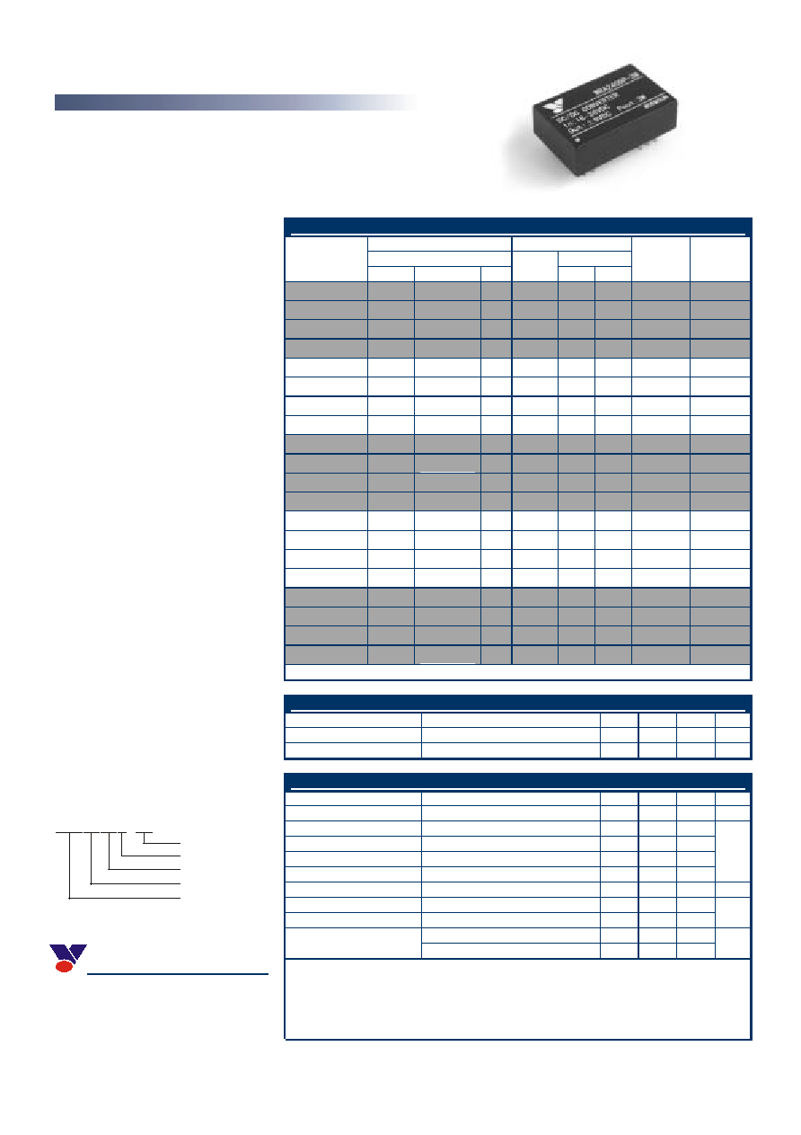
PRODUCT PROGRAM
Input Output
Voltage (VDC)
Current (mA)
Part
Number
Nominal
Range Max*
Voltage
(VDC)
Max Min
Efficiency
(%, Typ)
Package
Style
WRA0505P-3W
5
4.5~9VDC
11
±5
300
30
65
DIP
WRA0509P-3W
5
4.5~9VDC
11
±9
165
16
67
DIP
WRA0512P-3W
5
4.5~9VDC
11
±12
125
12
70
DIP
WRA0515P-3W
5
4.5~9VDC
11
±15
100
10
72
DIP
WRA1205P-3W
12
9~18VDC
22
±5 300 30 72
DIP
WRA1209P-3W
12
9~18VDC
22
±9 165 16 73
DIP
WRA1212P-3W
12
9~18VDC
22
±12 125 12
77
DIP
WRA1215P-3W
12
9~18VDC
22
±15 100 10
79
DIP
Wide (2:1) Input Range
Efficiency to 82%
Operating Temperature:
-40
∞C
~+85
∞C
1KVDC Isolation
Dual Output
UL94-V0 Package
No Heat sink Required
Industry Standard Pin out
MTBF>1,000,000 hours
Custom Service Available
WRA1505P-3W
15
12~24VDC
30
±5
300
30
75
DIP
APPLICATIONS
WRA1509P-3W
15
12~24VDC
30
±9
165
16
79
DIP
WRA1512P-3W
15
12~24VDC
30
±12
125
12
80
DIP
WRA1515P-3W
15
12~24VDC
30
±15
100
10
81
DIP
WRA2405P-3W
24 18~36VDC
40
±5 300 30
78
DIP
WRA2409P-3W
24
18~36VDC
40
±9 165 16 80
DIP
WRA2412P-3W
24
18~36VDC
40
±12 125 12
81
DIP
WRA2415P-3W
24
18~36VDC
40
±15 100 10
82
DIP
WRA4805P-3W
48
36~72VDC
80
±5
300
30
76
DIP
WRA4809P-3W
48
36~72VDC
80
±9
165
16
81
DIP
WRA4812P-3W
48
36~72VDC
80
±12
125
12
81
DIP
WRA4815P-3W
48
36~72VDC
80
±15
100
10
82
DIP
ISOLATION SPECIFICATIONS
Item Test
conditions
Min
Typ
Max
Units
Isolation voltage
Flash tested for 60 seconds
1000
VDC
Isolation resistance
Test at 500VDC
1000
M
OUTPUT SPECIFICATIONS
Item Test
conditions
Min
Typ
Max
Units
3W output power
See below products program
0.3
3
W
Positive Voltage accuracy
Refer to recommended circuit
±1
±3
Negative Voltage accuracy
Refer to recommended circuit
±3
±5
Load regulation
From 10% to 100% load
±0.1
±0.2
Line regulation
Input Voltage From Low to High
±0.2
±0.5
%
Temperature drift (Vout)
Refer to recommended circuit
0.03
%/∞C
Ripple 20Hz-300KHz
bandwidth
30
60
Noise DC-20MHz
bandwidth
80
150
mVp-p
The WRAP-3W Series are specially
designed for applications where a wide
range input voltage power supplies are
isolated from the input power supply in a
distributed power supply system on a circuit
board.
These products apply to:
1) Where the voltage of the input power
supply is wide range (voltage range: 2:1);
2) Where isolation is necessary between
input and output
(isolation voltage =1000VDC);
3) Where the regulation of the output
voltage and the output ripple noise are
demanding.
These products don't apply to:
1) Where the input voltage t is required to be
more than 2:1;
2) Where the isolation voltage between
input and output is required to be
>1000VDC;
3) The output load's actual power
consumption is less than 1W, otherwise our
company's WRAP
-
1W/0.5W series are
recommended.
MODEL SELECTION
WRA0505P-3W
Product Series
Input Voltage
Output Voltage
Package Style
Rated Power
100% loadnominal input voltage
80
200
Switching frequency
10% loadnominal input voltage
250
600
KHz
MORNSUN Science& Technology Ltd.
Address: 8th floor 8th building, Huangzhou
Industrial District, Guangzhou, China
Tel: 86-20-85571041
Fax: 86-20-85536272
Http://www.mornsun.cn/
Note:
1.All specifications measured at T
A
=25
∞C
, humidity<75%, nominal input voltage and rated output load unless
otherwise specified.
2.See below recommended circuits for more details.

Edition: Preliminary / Page 2 of 2
COMMON SPECIFICATION
Output Short Circuit Protection Continuous
Temperature Rise at Full Load
30
∞
C (TYP)
Cooling Free
Air
Convection
No-load Power Consumption
100mW (typical)
Operating Temperature Range
-40∞C~+85∞C
Storage Temperature Range
-55∞C ~+125∞C
Lead Temperature***
300∞C (1.5mm from case for 10 seconds)
Figure 1)
V in
GN D
+Vo
0 V
DC
C
L
L
DC
L
C
C
-Vo
Vin
GN D
+Vo
0V
DC
C
DC
C
C
-Vo
C
C
Storage Humidity Range
95%
Case Material
Plastic (UL94-V0)
MTBF >1,000,000
hours
***Lead Temperature 1.5mm from case for 10 seconds.
TYPICAL CHARECTERISTICS
FOOTPRINT DETAILS
2 3
9 1011
2322
16 1514
2,3
10,15
14
11
9,16
22,23
GND
NC
+Vo
-Vo
0V
Vin
Pin
WRAP Series
Bottom View
OUTLINE DIMENSIONS & RECOMMENDED FOOTPRINT
2 3
9 10 11
23 22
1615 14
2 x 2.54
31.80
15.24
2.54
22.86
(Bottom View)
(Side View)
20.30
9.45
0.50
4.00
supply and the rippled voltage do not exceed the
module standard. Input current of power supply
should afford the startup current of this kind of
DC/DC module. (See figure 2)
External Capacitor
Although this series of DC/DC converter can
work without external capacitor, in order to keep
an optimum performance, however, it needs
external capacitor. (See Table 1)
Requirement on Output Load
To ensure this module operate efficiently and
reliably, a minimum load is specified for this kind
of DC/DC converter in addition to a maximum
load (namely full load). During operation, make
sure the specified range of input voltage is not
exceeded, the minimum out put load is not less
than
10%
Of the full load, and that this product
should never be operated under no
load!!!
If the actual load is less below the
specified minimum loadthe output ripple of this
type of DC/DC converter will increase drastically
and at the same time efficiency & reliability of
the circuit will decrease deeply .If the actual
output power from the load in your circuit is very
smallplease connect a resistor with proper
resistance at the output end to in parallel to
increase the load, or use our company's other
products with a lower rated output power.
The products cannot be used in
parallel and in plug and play.
External Capacitor Table
(Table 1)
Vin C
in
C
out
(0+70
∞C
)
C
out
(-40+85
∞C
)
5V
&
12V
100uF
24V
&
48V
10uF
100uF
(electrolytic
capacitor)
47uF
(tantalum
capacitor)
Note: All Pins on a 2.54mm pitch; All Pin diameters are 0.50 mm(Tolerance:±0.25); All dimensions in
mm. The dimensions of the WRAP series are correspondent with the WRBP series.
APPLICATION NOTE
MORNSUN Science& Technology Ltd.
Recommended Circuit
All the WRA-3W Series have been tested according to the following recommended testing circuit
before leaving factory. This series should be tested under load. Never be tested under no load (See
Figure 1 & 2). If you want to further decrease the input/output ripple, you can increase capacitance
properly or choose capacitors with low ESR. However, the capacitance should not be too high.(See
table 1).If you want to use the products in high EMI, please choose our metal packaged products.
Input Current
When it is used in unregulated power supplybe sure that the fluctuating range of the power
Address: 8th Floor 8th Building, Huangzhou
Industrial District, Guangzhou, China
Tel :86-20-85571041
Fax:86-20-85536272
Http:// www.mornsun.cn/