
Edition 1.1
July 2004
1
1,550nm DWDM Direct
Modulation DFB Laser
FEATURES
∑ Direct Modulated DFB Laser for WDM systems
∑ Optimized for Long Distance Transmission (Dispersion 3200ps/nm)
∑ Peak wavelength 1527.99 to 1563.05nm (C Band: 191.8 to 196.2THz,
100GHz spacing)
∑ Output Power: 10mW
∑ 14-pin Butterfly type package
∑ Power monitor PIN-PD (InGaAs), Thermistor, cooler
∑ Built-in optical isolator
∑ Single mode fiber
APPLICATIONS
This laser is intended for the application of 2.5 Gb/s
long haul Dense Wavelength Division Multiplexing (DWDM).
Transmission spans of 3200ps/nm are possible.
DESCRIPTION
This high power laser is capable of 2.5 Gb/s transmission. It is packaged in a "butterfly" type module.
The module employs a high efficiency optical coupling system, coupling the laser output through a
built-in optical isolator into a single mode fiber pigtail. The module also includes a monitor photodiode,
a thermoelectric cooler (TEC), and thermistor. This device is designed for use in DWDM direct
modulation transmission systems. Selected wavelengths specified to the ITU-T grid are available.
Parameter
LD Forward Current
Cooler Voltage
Symbol
Condition
IF
Photodiode Reverse Voltage
VDR
Vc
150
10
2.5
Ratings
mA
Photodiode Forward Current
IPF
20
V
V
Optical Output Power
Pf
12.0
CW
CW
mW
mA
LD Reverse Voltage
VR
2
V
Unit
ABSOLUTE MAXIMUM RATINGS (Tc=25∞C, unless otherwise specified)
Cooler Current
Ic
95
95
A
260
∞C
Lead Soldering Time
Tsold
10 sec
ATC Operation
Thermistor Temperature
Tth
+70
∞C
Environmental Operating Humidity
Environmental Storage Humidity
Xop
%
%
Storage Temperature
Tstg
+85
-
-
-
-
-
Cooling
-
Heating
1.4
Cooling
-
Heating
∞C
Operating Case Temperature
Top
+70
-
-
-
-
-
-
-
-
-
-20
-40
-2.5
-
-0.9
-20
∞C
Xst
Top<30
∞C
Tstg<30
∞C
Min.
Max.
FLD5F15CX-A

FLD5F15CX-A
2
Parameter
Symbol
OPTICAL AND ELECTRICAL CHARACTERISTICS (TL=Tset, Tc=25∞C, BOL, unless otherwise specified)
Conditions
Unit
Min.
Limits
Peak Wavelength
p
Note (2)
Note (4)
nm
Series Resistance
Rs
22
28
CW, pin 12, 13
25
Laser Set Temperature
Tset
-
∞C
20
35
-
Optical Output Power
Pf
CW
mW
-
10.0
-
Slope Efficiency
CW, Pf=10mW
mW/mA
-
0.14
-
Threshold Power
Pth
CW, IF=Ith
µW
150
-
-
Monitor Current
Im
CW, Pf=10mW, VDR=5V
mA
2.5
0.25
-
Tracking Error (Note 1)
TE
Im-APC, Tc=-20 to 70∞C
dB
+0.5
-0.5
-
Photodiode Dark Current
ID
VDR=5V
nA
100
-
2
Photodiode Capacitance
Ct
VDR=5V, f=1 MHz
pF
10
-
-
Photodiode Cutoff
fcm
VDR=5V, 50 load
MHz
-
100
-
Side Mode Suppression
Sr
Note (2)
dB
-
35
40
Rise/Fall Time
Tr, Tf
20% to 80%
nsec
0.125
-
-
Spectral Width (-20dB)
Note (2)
nm
0.3
-
-
Wavelength Stabilty with
Case Temperature
d
/dTc
Tc=-20 to +70
∞C
pm/
∞C
-1.0
-
+1.0
Wavelength Drift
Note (2), after 20 years
pm
+100
-100
-
Cutoff Frequency
fc
Pf=10mW, -3 dB
GHz
-
3.5
-
Threshold Current
Ith
CW
mA
4
40
-
Forward Voltage
VFDC
CW, IF=30 mA, pin 12, 13
V
-
1.6
1.75
Max.
Typ.
f=50 MHz to 2 GHz
dB
8
-
-
RF Return Loss
S11
f=2 GHz to 3 GHz
f=3 GHz to 5 GHz
dB
dB
6
-
3
-
-
-
1,550nm DWDM Direct
Modulation DFB Laser
3
FLD5F15CX-A
Parameter
Cooler Voltage
Cooler Power
Thermistor Resistance
Thermistor B Constant
Symbol
Ic
Vc
Rtr
B
TL=Tset,
Pf=10mW,
Tc=70
∞C
TL=25
∞C
Test Conditions
A
V
W
K
k
Unit
Pc
Limit
1.0
2.4
2.4
10.5
Max.
Typ.
-
-
-
9.5
-
-
-
10.0
3630
3270
3450
Min.
Cooler Current
Relative Intensity Noise
RIN
f=2.5 GHz
Pf=10 mW, ORL=24 dB
dB/Hz
-140
-
-
dB
Power Penalty
PP
Note (2)
2.0
-
-
Optical Isolation
Is
Tc=-20 to 70
∞C
dB
-
25
35
Kink
Kns
-
No Kink
up to 12mW
Note 1. TE=10*log{Pf(Tcase)/Pf(Tc=25
∞C)} (dB)
Note 2. 2.5 Gb/s NRZ, Ppeak=10.0mW, Rext=8.2dB, PRBS=2
23
-1,
Note 3. Bit rate=2.48832 Gb/s, PRBS=2
23
-1, Dispersion=3200ps/nm, Ppeak=10mW,
Rext=8.2dB
(min.)
Receiver: Eudyna Standard Receiver
Note 4. The selected wavelengths available are listed in Fig. 8
OPTICAL AND ELECTRICAL CHARACTERISTICS (TL=Tset, TL: Laser Temperature,
Tc=25∞C, BOL, unless otherwise specified)
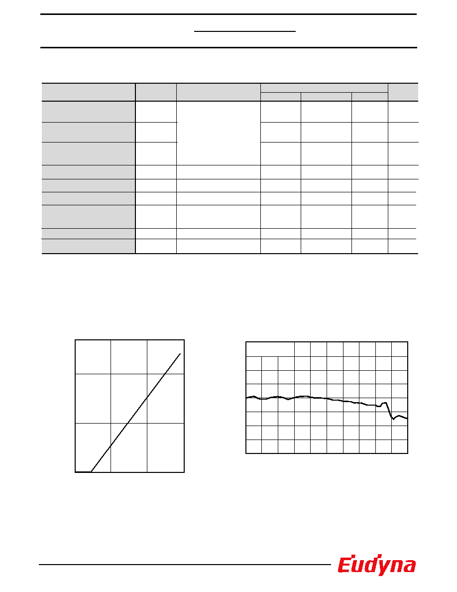
Fig. 1 Forward Current vs Output Power
Forward Current, If (mA)
Output Power, Pf (mW)
0
5
10
0
30
60
90
Fig. 2 Frequency Response
Frequency (GHz)
Relative Output (dB)
6
3
0
-3
-6
-9
-12
9
12
0
1
2
3
4
5
Pf=10mW
TL = 25∞C
1,550nm DWDM Direct
Modulation DFB Laser

4
FLD5F15CX-A
Fig. 4 Cooler Voltage -Current
Case Temperature (
∞C)
Cooler Voltage (V)
Cooler Current (A)
-1.0
3.0
2.0
0.0
1.0
-1.0
3.0
2.0
0.0
1.0
0
20
30
10
40
50
60
Ic
Vc
70
80
Fig. 3 RF Return Loss
Frequency (GHz)
Return Loss (dB)
10
0
-10
-20
-30
20
30
0
1
2
3
4
5
Fig. 5 Spectrum
Wavelength
(nm)
Relative Intensity (dB)
0
-10
-40
-50
-60
-20
-30
10
1540
1550
1560
Fig. 6 Temperature Dependance of
Wavelength (ACC Operation)
Laser Temperature, TL (∞C)
Wavelength (nm)
1550
1551
1552
1553
1554
10
20
30
40
1,550nm DWDM Direct
Modulation DFB Laser

5
FLD5F15CX-A
Fig. 7 Transmission Characteristics
Average Received Optical Power (dBm)
Bit Error Rate
10
-12
10
-10
10
-8
10
-6
10
-4
-37
-33
-29
-25
2.5Gb/s, NRZ,
PRBS=2
23
-1,
Pave=7dBm,
Rext
9dB,
Dispersion penalty
2dB@10
-10
Fig. 8 Wavelength Table
Part Number
FLD5F15CX-A9620
-A9610
-A9600
-A9590
-A9580
-A9570
-A9560
-A9550
-A9540
-A9530
-A9520
-A9510
-A9500
-A9490
-A9480
-A9470
1527.99
1528.77
1529.55
1530.33
1531.12
1531.90
1532.68
1533.47
1534.25
1535.04
1535.82
1536.61
1537.40
1538.19
1538.98
1539.77
1540.56
1541.35
1542.14
1542.94
1543.73
±0.1
±0.1
±0.1
±0.1
±0.1
±0.1
±0.1
±0.1
±0.1
±0.1
±0.1
±0.1
±0.1
±0.1
±0.1
±0.1
±0.1
±0.1
±0.1
±0.1
±0.1
Wavelength (nm)
(TL=Tset)
(in vacuum)
Tolerance (nm)
-A9460
-A9450
-A9440
-A9430
-A9420
1544.53
1545.32
1546.12
±0.1
±0.1
±0.1
-A9410
-A9400
-A9390
-A9380
-A9370
-A9360
-A9350
-A9340
-A9330
-A9320
-A9310
-A9300
-A9290
-A9280
-A9270
-A9260
-A9250
-A9240
-A9230
-A9220
-A9210
-A9200
-A9190
-A9180
1546.92
1547.72
1548.51
1549.32
1550.12
1550.92
1551.72
1552.52
1553.33
1554.13
1554.94
1555.75
1556.55
1557.36
1558.17
1558.98
1559.79
1560.61
1561.42
1562.23
1563.05
±0.1
±0.1
±0.1
±0.1
±0.1
±0.1
±0.1
±0.1
±0.1
±0.1
±0.1
±0.1
±0.1
±0.1
±0.1
±0.1
±0.1
±0.1
±0.1
±0.1
±0.1
Back to Back
After Transmission
(3200ps/nm)
1,550nm DWDM Direct
Modulation DFB Laser

6
FLD5F15CX-A
PIN 7
8.25
±
0.5
5.25
±
0.5
20.83
±0.25
22.0
±0.25
26.04
±0.25
PIN 8
4-ÿ2.67
PIN 1
29.97
±0.25
25.0
±0.5
PIN 14
14-0.5
5.4
±0.5
15.24
±0.25
17.24
±0.25
2.54
*L
Grounded Type
1. Thermistor
2. Thermistor
3. Laser DC Bias (-)
4. Monitor (Anode)
5. Monitor (Cathode)
6. Thermoelectric Cooler (+)
7. Thermoelectric Cooler (-)
8. Case Ground
9. Case Ground
10. N.C.
11. Case Ground
12. Laser Modulation (-)
13. Case Ground
14. N.C.
PIN #
FUNCTION
15.2
±
0.3
5.08
±
0.15
ÿ
0.9
±
0.1
12.7
±
0.25
8.89
±
0.15
ÿ
5.2
±
0.25
4.15
±0.25
5.47
±0.2
1.70
0.5
8.17
±0.25
1.70
±0.15
0.5
±0.2
5.41
±0.25
14-0.1
±0.05
CONNECTOR
8
9
10
11
12
13
14
1
2
3
4
5
6
7
TEC
"CX" PACKAGE
UNIT: mm
Eudyna Devices Inc. products contain gallium arsenide
(GaAs) which can be hazardous to the human body and the environment.
For safety, observe the following procedures:
CAUTION
∑ Do not put this product into the mouth.
∑ Do not alter the form of this product into a gas, powder, or liquid
through burning, crushing, or chemical processing as these by-products
are dangerous to the human body if inhaled, ingested, or swallowed.
∑ Observe government laws and company regulations when discarding this
product. This product must be discarded in accordance with methods
specified by applicable hazardous waste procedures.
For further information please contact:
Eudyna Devices USA Inc.
2355 Zanker Rd.
San Jose, CA 95131-1138, U.S.A.
TEL: (408) 232-9500
FAX: (408) 428-9111
www.us.eudyna.com
Eudyna Devices Europe Ltd.
Network House
Norreys Drive
Maidenhead, Berkshire SL6 4FJ
United Kingdom
TEL: +44 (0) 1628 504800
FAX: +44 (0) 1628 504888
Eudyna Devices Asia Pte Ltd.
Hong Kong Branch
Rm. 1101, Ocean Centre, 5 Canton Rd.
Tsim Sha Tsui, Kowloon, Hong Kong
TEL: +852-2377-0227
FAX: +852-2377-3921
Eudyna Devices Inc.
Sales Division
1, Kanai-cho, Sakae-ku
Yokohama, 244-0845, Japan
TEL: +81-45-853-8156
FAX: +81-45-853-8170
Eudyna Devices Inc. reserves the right to change products and specifications
without notice. The information does not convey any license under rights of
Eudyna Devices Inc. or others.
© 2004 Eudyna Devices USA Inc.
Printed in U.S.A.
1,550nm DWDM Direct
Modulation DFB Laser