 | –≠–ª–µ–∫—Ç—Ä–æ–Ω–Ω—ã–π –∫–æ–º–ø–æ–Ω–µ–Ω—Ç: FMM5820QH | –°–∫–∞—á–∞—Ç—å:  PDF PDF  ZIP ZIP |
1
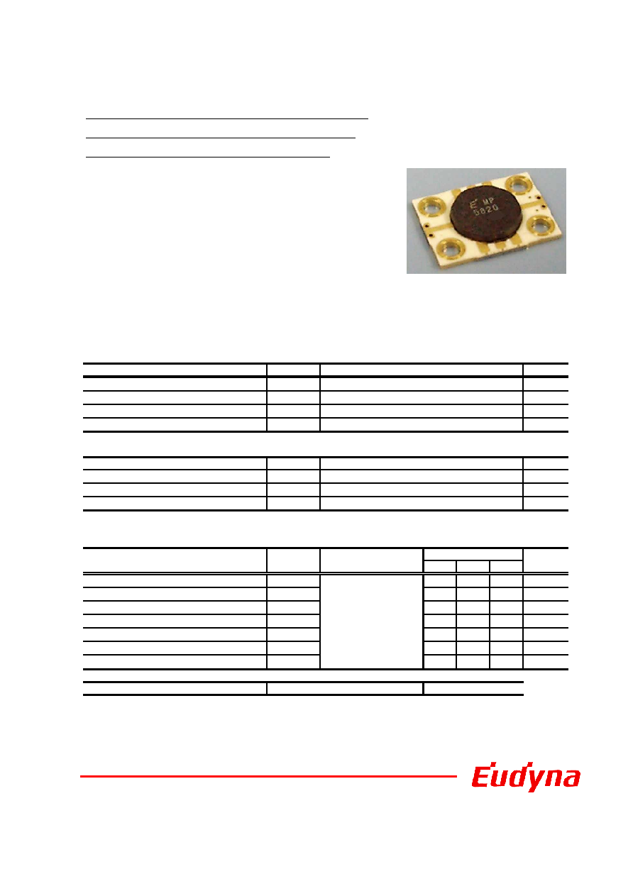
Ka-Band Power Amplifier MMIC
FEATURES
∑High Output Power: P1dB = 36.0 dBm (Typ.)
∑High Linear Gain: GL = 23.0 dB(Typ.)
∑Frequency Band: 29.5 - 30.0 GHz
∑Impedance Matched Zin/Zout = 50
Edition 1.1
January 2006
FMM5820QH
DESCRIPTION
The FMM5820QH is a power amplifier MMIC that contains a four-
stage amplifier, internally matched, for standard communications
band in the 29.5 to 30.0GHz frequency range. This product is well
suited for Ka-band V-SAT applications.
Eudyna's stringent Quality Assurance Program assures the
highest reliability and consistent performance.
ABSOLUTE MAXIMUM RATING(Case Temperature Tc=25
)
Item
Symbol
Unit
DC Positive Supply Voltage
V
DD
V
DC Negative Supply Voltage
V
GG
V
Input Power
P
in
dBm
Storage Temperature
T
stg
RECOMMENDED OPERATING CONDITIONS
Item
Symbol
Unit
DC Positive Supply Voltage
V
DD
V
Input Power
P
in
dBm
Operating Case Temperature
T
C
This product should be hermetically packaged.
ELECTRICAL CHARACTERISTICS (Case Temperature Ta=25
)
Min.
Typ.
Max.
RF Frequency Range
f
29.5
-
30.0
GHz
Output Power at 1dB G.C.P.
P
1dB
34.5
36.0
-
dBm
Power Gain at 1dB G.C.P.
G
1dB
18.0
22.0
26.0
dB
Power-added Efficiency at 1dB G.C.P.
N
add
-
25
-
%
Drain Current at 1dB G.C.P.
I
DDRF
-
2200
2800
mA
Input Return Loss (at Pin=-20dBm)
RL
IN
-
-10
-
dB
Output Return Loss (at Pin=-20dBm)
RL
OUT
-
-15
-
dB
ESD
Note : Based on EIAJ ED-4701C-111A (C=100pF, R=1.5k
)
-40 to +85
Unit
Limits
Item
Symbol
Test Conditions
-55 to +125
Class 0
~199V
Rating
10
-3
+24
V
DD
=+7V
I
DD
=1500mA typ.
Z
S
=Z
L
=50ohm
Recommend
7
21
http://www.eudyna.com/

2
16
18
20
22
24
26
28
30
32
34
36
38
-6 -4 -2 0 2 4 6 8 10 12 14 16 18 20 22
Input Power [dBm]
Output Power [dB
m
]
1200
1400
1600
1800
2000
2200
2400
2600
2800
3000
3200
3400
Dr
ain
Cu
r
r
e
n
t
[
m
A]
29.5GHz
29.75GHz
30.0GHz
29 5GH
Pout
Drain Current
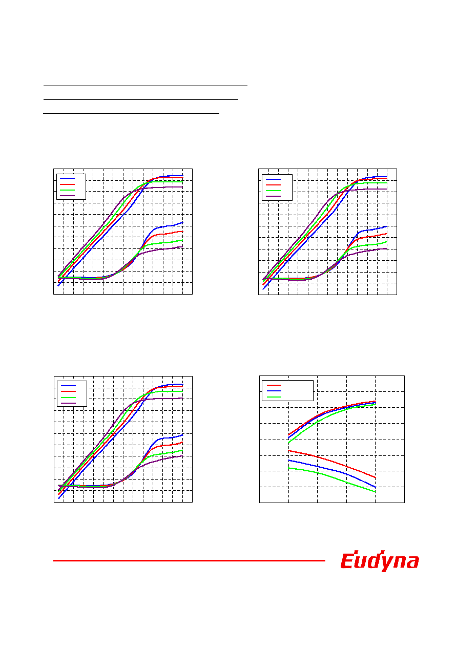
Output Power vs. Frequency
Ka-Band Power Amplifier MMIC
FMM5820QH
Output Power, Drain Current vs. Input Power
Power Added Efficiency vs. Frequency
22
24
26
28
30
32
34
36
38
27.5
28
28.5
29
29.5
30
30.5
31
31.5
Frequency [GHz]
Output Power [dB
m
]
Pin=4dBm
Pin=8dBm
Pin=12dBm
Pin=16dBm
P1dB
VDD=7V, IDD(DC)=1500mA
VDD=7V, IDD(DC)=1500mA
0
5
10
15
20
25
30
27.5
28
28.5
29
29.5
30
30.5
31
31.5
Frequency [GHz]
P
o
we
r Adde
d E
f
i
c
i
e
nc
y
[%
]
Pin=4dBm
Pin=8dBm
Pin=12dBm
Pin=16dBm
P1dB
VDD=7V, IDD(DC)=1500mA
-60
-55
-50
-45
-40
-35
-30
-25
-20
-15
18
20
22
24
26
28
30
32
34
36
2-tone Total Output Power [dBm]
Inte
r
m
odula
t
ion D
i
s
t
or
tion [dB
c
]
29.5GHz
29.75GHz
30.0GHz
29 5GH
IM3
IM5
IMD vs. Output Power
VDD=7V, IDD(DC)=1500mA
3
Ka-Band Power Amplifier MMIC
FMM5820QH
16
18
20
22
24
26
28
30
32
34
36
38
-6 -4 -2 0 2 4 6 8 10 12 14 16 18 20 22
Input Power [dBm]
Output P
o
we
r
[dBm]
1200
1400
1600
1800
2000
2200
2400
2600
2800
3000
3200
3400
Drain Current [mA
]
8V
7V
6V
5V
Pout
Drain Current
16
18
20
22
24
26
28
30
32
34
36
38
-6 -4 -2 0 2 4 6 8 10 12 14 16 18 20 22
Input Power [dBm]
Output Power
[dBm]
1200
1400
1600
1800
2000
2200
2400
2600
2800
3000
3200
3400
Drain Current
[
m
A
]
8V
7V
6V
5V
8V
Pout
Drain Current
16
18
20
22
24
26
28
30
32
34
36
38
-6 -4 -2 0 2 4 6 8 10 12 14 16 18 20 22
Input Power [dBm]
Output Power
[dBm]
1200
1400
1600
1800
2000
2200
2400
2600
2800
3000
3200
3400
Drain Current
[
m
A
]
8V
7V
6V
5V
Pout
Drain Current
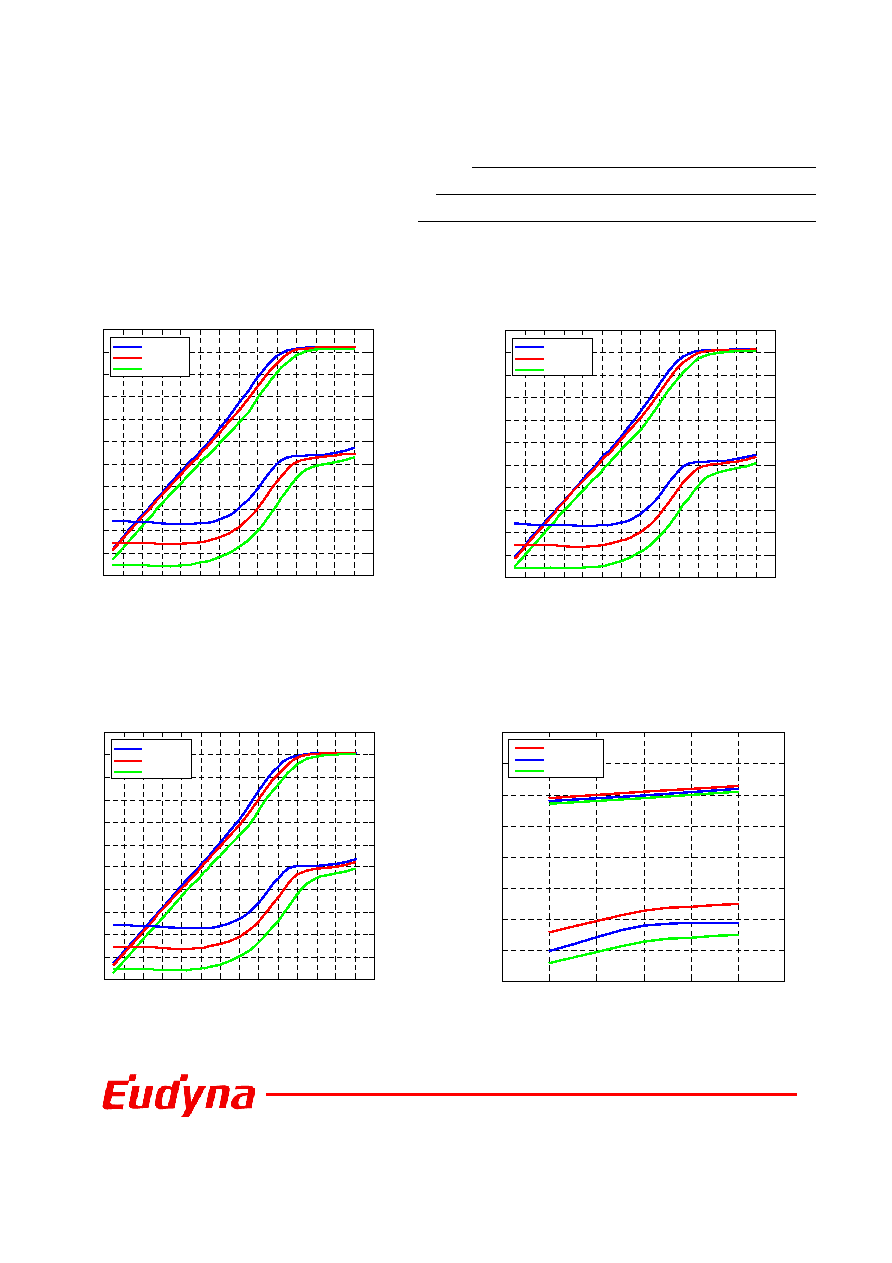
Output Power, Drain Current vs.
Input Power by Drain Voltage
IDD(DC)=1500mA, f=29.5GHz
Output Power, Drain Current vs.
Input Power by Drain Voltage
IDD(DC)=1500mA, f=29.75GHz
Output Power, Drain Current vs.
Input Power by Drain Voltage
IDD(DC)=1500mA, f=30.0GHz
30
31
32
33
34
35
36
37
38
4
5
6
7
8
9
VDD [V]
P1dB [dBm]
20
21
22
23
24
25
26
27
28
G1
dB
[dB
]
29.5GHz
29.75GHz
30.0GHz
29 GH
P1dB
G1dB
Output Power, Gain vs. Drain Voltage
IDD(DC)=1500mA
4
Ka-Band Power Amplifier MMIC
FMM5820QH
16
18
20
22
24
26
28
30
32
34
36
38
-6 -4 -2 0 2 4 6 8 10 12 14 16 18 20 22
Input Power [dBm]
Output Power
[dBm]
1200
1400
1600
1800
2000
2200
2400
2600
2800
3000
3200
3400
Dr
ain Cur
r
e
nt
[
m
A
]
1700mA
1500mA
1300mA
Pout
Drain Current
Output Power, Drain Current vs.
Input Power by Drain Current
VDD=7V, f=29.5GHz
16
18
20
22
24
26
28
30
32
34
36
38
-6 -4 -2 0 2 4 6 8 10 12 14 16 18 20 22
Input Power [dBm]
Output Powe
r
[dB
m
]
1200
1400
1600
1800
2000
2200
2400
2600
2800
3000
3200
3400
Drai
n
Cu
rren
t
[mA]
1700mA
1500mA
1300mA
Pout
Drain Current
Output Power, Drain Current vs.
Input Power by Drain Current
VDD=7V, f=29.75GHz
16
18
20
22
24
26
28
30
32
34
36
38
-6 -4 -2 0 2 4 6 8 10 12 14 16 18 20 22
Input Power [dBm]
Output Power
[dBm]
1200
1400
1600
1800
2000
2200
2400
2600
2800
3000
3200
3400
Drain Current
[
m
A
]
1700mA
1500mA
1300mA
Pout
Drain Current
Output Power, Drain Current vs.
Input Power by Drain Current
VDD=7V, f=30.0GHz
30
31
32
33
34
35
36
37
38
1200
1300
1400
1500
1600
1700
1800
IDD(DC) [mA]
P1dB [dBm]
20
21
22
23
24
25
26
27
28
G1
dB
[dB
]
29.5GHz
29.75GHz
30.0GHz
P1dB
G1dB
Output Power, Gain vs. Drain Voltage
VDD=7V
5
Ka-Band Power Amplifier MMIC
FMM5820QH
-60
-55
-50
-45
-40
-35
-30
-25
-20
-15
20
22
24
26
28
30
32
34
36
2-tone Total Output Power [dBm]
Interm
odulation D
i
stortion [dB
c
]
8V
7V
6V
5V
IM3
IM5
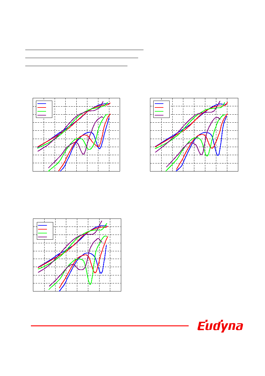
IMD vs. Output Power
by Drain Voltage
IDD(DC)=1500mA, f=29.5GHz
-60
-55
-50
-45
-40
-35
-30
-25
-20
-15
20
22
24
26
28
30
32
34
36
2-tone Total Output Power [dBm]
I
n
t
e
rm
odul
at
i
on Di
st
ort
i
on [
d
Bc
]
8V
7V
6V
5V
IM3
IM5
IMD vs. Output Power
by Drain Voltage
IDD(DC)=1500mA, f=29.75GHz
-60
-55
-50
-45
-40
-35
-30
-25
-20
-15
20
22
24
26
28
30
32
34
36
2-tone Total Output Power [dBm]
I
n
t
e
rm
odul
at
i
on Di
st
ort
i
on [
d
Bc
]
8V
7V
6V
5V
IM3
IM5
IMD vs. Output Power
by Drain Voltage
IDD(DC)=1500mA, f=30.0GHz

6
IMD vs. Output Power
by Drain Current
VDD=7V, f=30.0GHz
Ka-Band Power Amplifier MMIC
FMM5820QH
-60
-55
-50
-45
-40
-35
-30
-25
-20
-15
20
22
24
26
28
30
32
34
36
2-tone Total Output Power [dBm]
I
n
termodul
ati
on D
i
storti
on [dB
c
]
1700mA
1500mA
1300mA
1700 A
IM3
IM5
IMD vs. Output Power
by Drain Current
VDD=7V, f=29.5GHz
-60
-55
-50
-45
-40
-35
-30
-25
-20
-15
20
22
24
26
28
30
32
34
36
2-tone Total Output Power [dBm]
Int
e
rm
odulat
ion D
i
st
ort
i
on [
d
B
c
]
1700mA
1500mA
1300mA
1700 A
IM3
IM5
IMD vs. Output Power
by Drain Current
VDD=7V, f=29.75GHz
-60
-55
-50
-45
-40
-35
-30
-25
-20
-15
20
22
24
26
28
30
32
34
36
2-tone Total Output Power [dBm]
I
n
termodul
ati
on D
i
storti
on [dB
c
]
1700mA
1500mA
1300mA
IM3
IM5
7
Ka-Band Power Amplifier MMIC
FMM5820QH
-30
-25
-20
-15
-10
-5
0
5
10
15
20
25
30
0
5
10
15
20
25
30
35
40
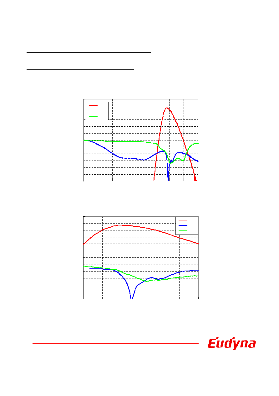
Frequency [GHz]
S
xx [d
B
]
S21
S11
S22
S-Parameter
VDD=7V, IDD=1500mA
-30
-25
-20
-15
-10
-5
0
5
10
15
20
25
30
27
28
29
30
31
32
33
Frequency [GHz]
S
xx [d
B
]
S21
S11
S22

8
Ka-Band Power Amplifier MMIC
FMM5820QH
S-Parameter
VDD=7V, IDD=1500mA
Frequency
[GHz]
MAG
ANG
MAG
ANG
MAG
ANG
MAG
ANG
1.0
0.99
-34.5
0.00
-117.8
0.00
-47.1
0.99
-83.8
2.0
0.94
-68.2
0.00
131.5
0.00
18.1
0.96
-141.7
3.0
0.87
-100.3
0.00
175.5
0.00
-159.3
0.96
177.1
4.0
0.78
-131.2
0.00
-165.2
0.00
149.3
0.97
143.8
5.0
0.69
-160.0
0.00
-64.6
0.00
2.0
0.97
114.5
6.0
0.61
172.4
0.00
-53.0
0.00
-0.3
0.96
86.8
7.0
0.54
144.9
0.00
-25.2
0.00
-42.0
0.94
60.4
8.0
0.46
117.0
0.00
40.3
0.00
60.1
0.91
35.9
9.0
0.39
88.7
0.00
74.2
0.00
-36.7
0.89
13.5
10.0
0.33
59.1
0.00
130.3
0.00
-100.5
0.89
-8.9
11.0
0.28
27.4
0.00
-160.3
0.00
-72.5
0.90
-32.0
12.0
0.25
-6.1
0.01
-144.6
0.00
-118.7
0.91
-55.5
13.0
0.23
-40.0
0.01
-134.8
0.00
-134.4
0.91
-78.9
14.0
0.22
-74.6
0.01
-134.7
0.00
-171.8
0.91
-101.8
15.0
0.22
-105.9
0.00
-25.0
0.00
162.1
0.91
-125.1
16.0
0.22
-135.8
0.00
50.1
0.00
-165.7
0.91
-148.1
17.0
0.21
-165.4
0.00
116.1
0.00
161.4
0.91
-170.9
18.0
0.21
165.3
0.01
107.9
0.00
120.5
0.91
165.1
19.0
0.20
134.4
0.01
130.9
0.01
107.2
0.91
139.5
20.0
0.19
103.8
0.01
155.0
0.00
89.4
0.89
112.9
21.0
0.19
70.3
0.00
127.9
0.00
45.6
0.86
85.3
22.0
0.20
35.9
0.00
-38.8
0.00
-6.7
0.84
55.8
23.0
0.23
2.6
0.01
-25.1
0.00
-26.4
0.81
23.9
24.0
0.27
-29.0
0.01
-128.4
0.00
-83.2
0.78
-10.7
25.0
0.31
-57.9
0.10
142.9
0.00
36.5
0.76
-50.2
26.0
0.35
-86.3
0.67
46.3
0.00
-18.3
0.65
-97.4
27.0
0.39
-114.9
3.09
-88.2
0.00
-84.9
0.48
-133.9
28.0
0.38
-150.7
10.15
113.8
0.00
-94.9
0.42
-177.2
29.0
0.21
151.2
15.32
-57.8
0.00
-164.1
0.30
116.0
30.0
0.12
-123.6
12.81
150.5
0.00
172.3
0.16
24.3
31.0
0.17
-134.2
9.00
10.2
0.00
158.0
0.15
-73.3
32.0
0.29
-140.8
5.31
-115.2
0.00
80.9
0.19
-127.0
33.0
0.35
-171.6
3.17
126.8
0.00
-114.1
0.21
-175.2
34.0
0.35
165.1
1.72
14.8
0.00
85.6
0.19
122.8
35.0
0.33
141.5
0.85
-91.9
0.01
12.9
0.19
29.5
36.0
0.30
117.3
0.42
170.5
0.00
-27.8
0.35
-58.3
37.0
0.26
90.9
0.20
67.7
0.00
-53.7
0.55
-119.6
38.0
0.22
59.2
0.09
-39.6
0.00
-77.5
0.69
-168.7
39.0
0.19
22.3
0.04
-136.1
0.01
-119.2
0.74
147.8
40.0
0.17
-20.3
0.02
-156.4
0.01
-114.8
0.74
106.3
S11
S21
S12
S22

9
1.E+01
1.E+02
1.E+03
1.E+04
1.E+05
1.E+06
1.E+07
1.E+08
1.E+09
1.E+10
1.E+11
1.E+12
50
100
150
200
250
Tch (
)
MTTF (
h
r
s
)
Ea=1.56eV
0
5
10
15
20
25
30
35
40
45
50
4
5
6
7
8
9
VDD (V)
Tch (
)
Ka-Band Power Amplifier MMIC
FMM5820QH
Tch vs. Drain Voltage
(Reference)
MTTF vs. Tch
IDD=1500mA
10
Ka-Band Power Amplifier MMIC
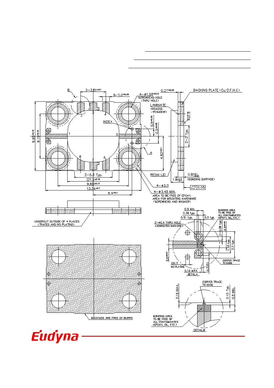
Package Outline
FMM5820QH
PIN ASSIGNMENT
1:RF IN
2:VGG
3:N.C.
4:VDD
5:RF OUT
6:N.C.
7:N.C.
8:N.C.
11
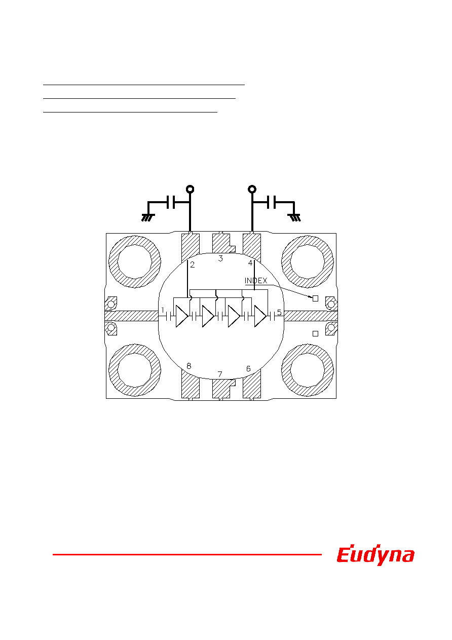
Ka-Band Power Amplifier MMIC
Block Diagram and Recommended Bias Circuit
FMM5820QH
1:RF IN
2:VGG
3:N.C.
4:VDD
5:RF OUT
6:N.C.
7:N.C.
8:N.C.
1uF
VGG
1uF
VDD
Note:The capacitors are recommended on the bias supply line, close to the package,
in order to prevent video oscillations which could damage the module.
12
Ka-Band Power Amplifier MMIC
Mounting Instructions for QH Package
FMM5820QH
(1) The package may be attached using screws. Torque conditions are shown in Table 1.
(2) First, tighten the screws with a torque driver set to 5 N-cm.
(3) The surface finish of the heat sink should be better than 0.8
µm, and the surface flatness
must be better than 10
µm.
(4) Silicon based heat sink compounds should not be used for the thermal conductive grease.
They cause poor grounding of the source flange, contamination and long term degradation
of thermal resistance between the MMIC package and the heat sink.
(5) The DC and RF interconnects may be gold bondwires or gold ribbons. The RF interconnects
should be as short as possible.
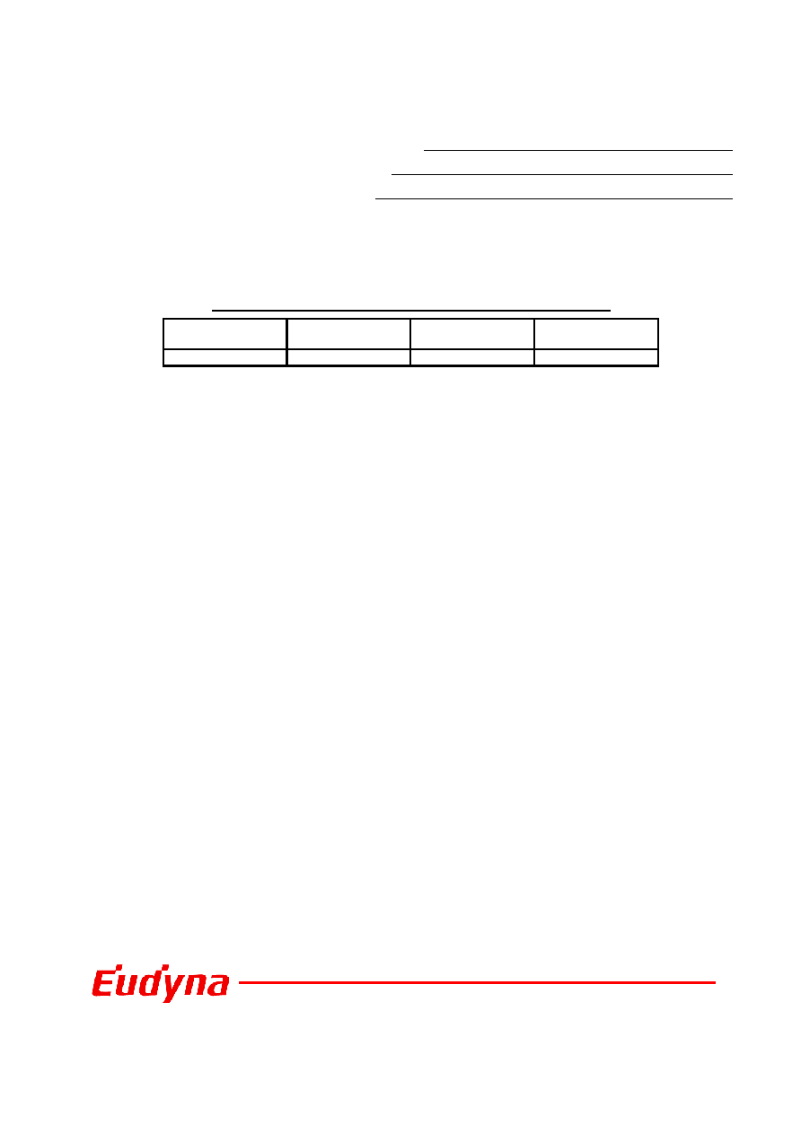
Package
Recommended
screw
Recommended
Torque
Maximum Torque
QH
M1.6*
15 N-cm (1.3 lb-in) 20 N-cm (1.8 lb-in)
Table 1. Recommended and Maximum Torque for Screw Mounting
*Mounting with flat washer is recommended.
13
Ka-Band Power Amplifier MMIC
FMM5820QH
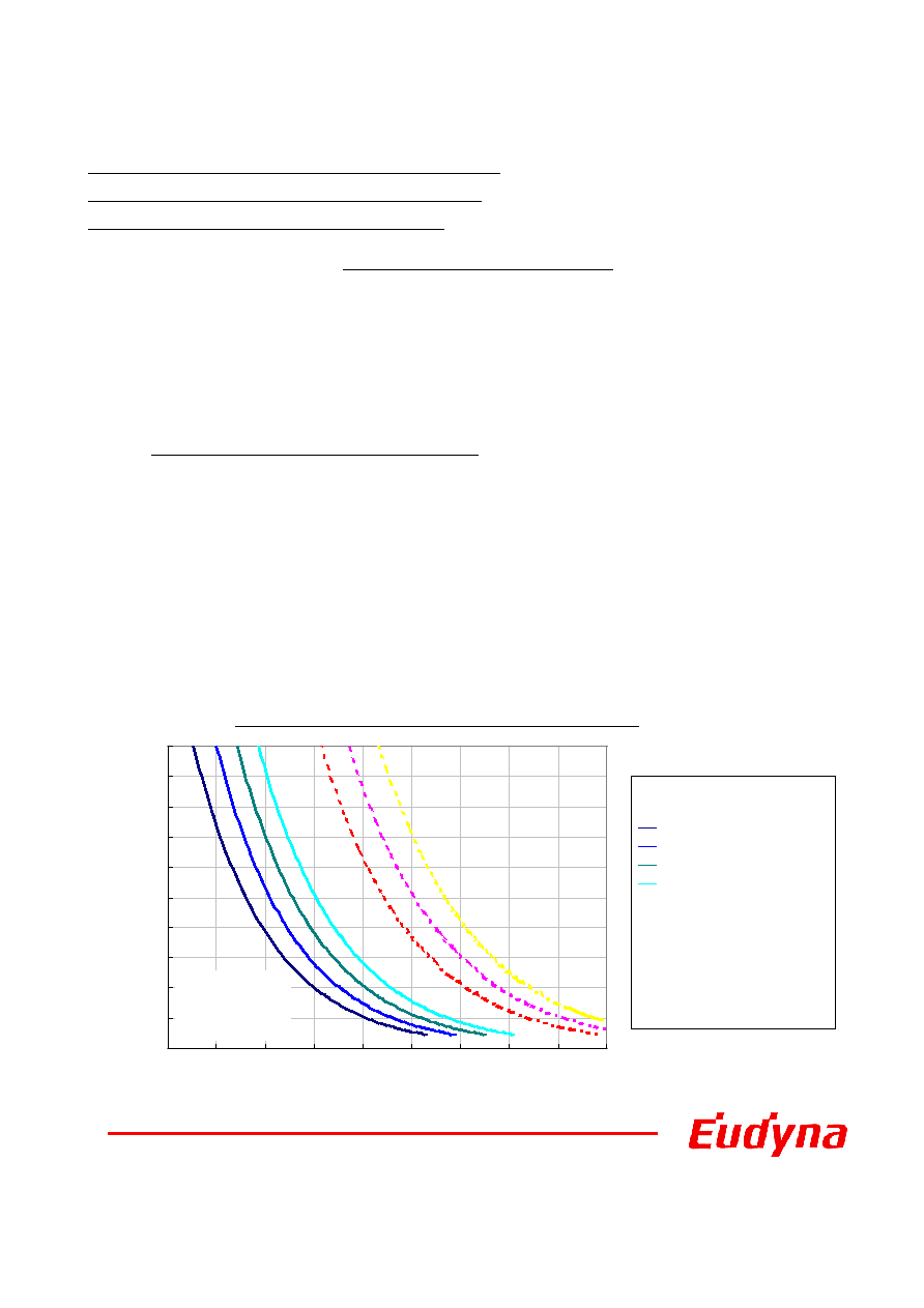
Humidity Lifetime for FMM5820QH
The following graph shows the lifetime of moisture resistance for the FMM5820QH. Each
line in the graph indicates the lifetime that is the estimated failure rate of 0.1% at 10 years
(Confidence Level = 90 %) and calculated from the results of pressure cooker (autoclave) bias
test. The horizontal-axis shows typical ambient temperature. The vertical-axis shows relative
humidity. The left side of the area delimited in each line indicates more than 10 years of
lifetime.
Field environmental conditions for operation
In the case that FMM5820QH is mounted in a non-hermetic package, please refer to the
following recommendations.
Note 1. The graph lines are drawn using the operating conditions as shown in the box below.
EUD recommends our customers use FMM5820QH within the left side area
separated by each line in the graph below.
Note 2. Please cut off the drain current by drain bias, not by gate bias.
The humidity lifetime becomes shorter in case of gate cut off operation.
Note 3. Please use FMM5820QH under environmental conditions of no dew condensation.
Field Environmental Conditions for a 10 years Lifetime
0%
10%
20%
30%
40%
50%
60%
70%
80%
90%
100%
0
10
20
30
40
50
60
70
80
90
Typical Ambient Temperature (deg-C)
Re
l
a
t
i
v
e
Hu
m
i
d
i
t
y
(%
)
Field
Environmental
Conditions.
(
)
[
[
[
[Gate cut off operating]
Gate cut off operating]
Gate cut off operating]
Gate cut off operating]
(
(
(
(Vdd
Vdd
Vdd
Vdd=6V,
=6V,
=6V,
=6V, Vgg
Vgg
Vgg
Vgg=0V -1 V)
=0V -1 V)
=0V -1 V)
=0V -1 V)
24 hours/day Cut off
24 hours/day Cut off
24 hours/day Cut off
24 hours/day Cut off
12 hours/day Cut off
12 hours/day Cut off
12 hours/day Cut off
12 hours/day Cut off
6 hours/day Cut off
6 hours/day Cut off
6 hours/day Cut off
6 hours/day Cut off
3 hours/day Cut off
3 hours/day Cut off
3 hours/day Cut off
3 hours/day Cut off
[Drain cut off operating]
[Drain cut off operating]
[Drain cut off operating]
[Drain cut off operating]
(
(
(
(Vgg
Vgg
Vgg
Vgg=-0V,
=-0V,
=-0V,
=-0V, Vdd
Vdd
Vdd
Vdd=6V 0V)
=6V 0V)
=6V 0V)
=6V 0V)
--- 0 hours/day Cut off
--- 0 hours/day Cut off
--- 0 hours/day Cut off
--- 0 hours/day Cut off
--- 12 hours/day Cut off
--- 12 hours/day Cut off
--- 12 hours/day Cut off
--- 12 hours/day Cut off
--- 18 hours/day Cut off
--- 18 hours/day Cut off
--- 18 hours/day Cut off
--- 18 hours/day Cut off

14
Ka-Band Power Amplifier MMIC
FMM5820QH
For further information please contact :
Eudyna Devices Inc. reserves the right to change products and
specifications without notice.The information does not convey any
license under rights of Eudyna Devices Inc. or others.
CAUTION
Eudyna Devices Inc. products contain gallium arsenide
(GaAs)
which can be hazardous to the human body and the
environment. For safety, observe the following procedures:
Do not put these products into the mouth.
Do not alter the form of this product into a gas, powder, or liquid
through burning, crushing, or chemical processing as these by-
products are dangerous to the human body if inhaled, ingested, or
swallowed.
Observe government laws and company regulations when
discarding this product. This product must be discarded in
accordance with methods specified by applicable hazardous waste
procedures.
© 2006 Eudyna Devices Inc.
Eudyna Devices USA Inc.
2355 Zanker Rd.
San Jose, CA 95131-1138, U.S.A.
TEL: +1 408 232-9500
FAX: +1 408 428-9111
Eudyna Devices Europe Ltd.
Network House
Norreys Drive
Maidenhead, Berkshire SL6 4FJ
United Kingdom
TEL: +44 (0) 1628 504800
FAX: +44 (0) 1628 504888
Eudyna Devices International Srl
Via Teglio 8/2 - 20158
Milano, Italy
TEL: +39-02-8738-1695
Eudyna Devices Asia Pte. Ltd.
Hong Kong Branch
Suite 1906B, Tower 6, China Hong Kong City
33 Canton Road, Tsimshatsui, Kowloon
Hong Kong
TEL: +852-2377-0227
FAX: +852-2377-3921
Eudyna Devices Inc.
1000 Kamisukiahara, showa-cho
Nakakomagun, Yamanashi
409-3883, Japan
(Kokubo Industrial Park)
TEL +81-55-275-4411
FAX +81-55-275-9461
Sales Division
1, Kanai-cho, Sakae-ku
Yokohama, 244-0845, Japan
TEL +81-45-853-8156
FAX +81-45-853-8170