�
�
�
�
�
�
�
�
!" #$%& ' $#()! $&"$*!"$#%!"+* ),!(
&( '!$#()! $&"$*! '! )!! !(!*#--# $#!&
&& "&!#* ).! !"$$" !* "$$#*
/#!+-.$+*"!# !"$!-!0+!#"!*
/1.& $!$#(&11!"#*+) #
))+# '$$#* $)%!# &
((!1 # !$ !(""+
22/$#(
3")$ %& '
/#!"! #(* $#"!
*!#* . '
�
�
2!(!."!*$)#$ +! '!#-$!(!) !"# &*'* !)!"!.!1"$*%!!#(!.!&!(
$#((!*#!(%'+ &,# !)* +($ !( !"#&'2!((!$#(!$)&-!$!
$**!)%&!(#&!$(-$)!4 !!5'$"6$!*(!*#!($*$#-& !2!(!)(+&$ !(+ +
*#$&"$#(!" &'%!(!"(!(%'$)""!**
��
! "
#* +)!# **+"$*+(424444! "
)!$&$#"!**+"$*"#( #!47$#4! "
2! !!0+)!# *1 1!&!**!) !"# &
2*! %5!*
+& )!($0+)!#
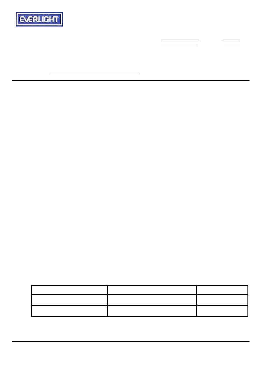
Chip
Silicon
Black
Shell
Tinplate
Silver-white

�
�
�
�
�
�
�
�
��
1. This drawing measure is a standard value.
All dimensions are in millimeter.
2. In case of designation is tolerance
0.3mm.
3. Lead spacing is measured where the lead
emerge from the package.
4. Protruded resin under flange 1.0mm Max.
5. Lens color: Black.
6. Above specification may be changed without
notice. EVERLIGHT will reserve authority
on material change for above specification.
7. These specification sheets include materials
protected under copyright of EVERLIGHT
corporation. Please don't reproduce or
cause anyone to reproduce them without
EVERLIGHT consent.
8. When using this produce, please observe the
absolute maximum ratings and the
instructions for use outlined in these
specification sheets. EVERLIGHT assumes
no responsibility for any damage resulting
from use of the product which does not
comply with the absolute maximum ratings
and the instructions included in these
specification sheets.
�
�
�
�
� 8
�
�
�
��
!
�
�
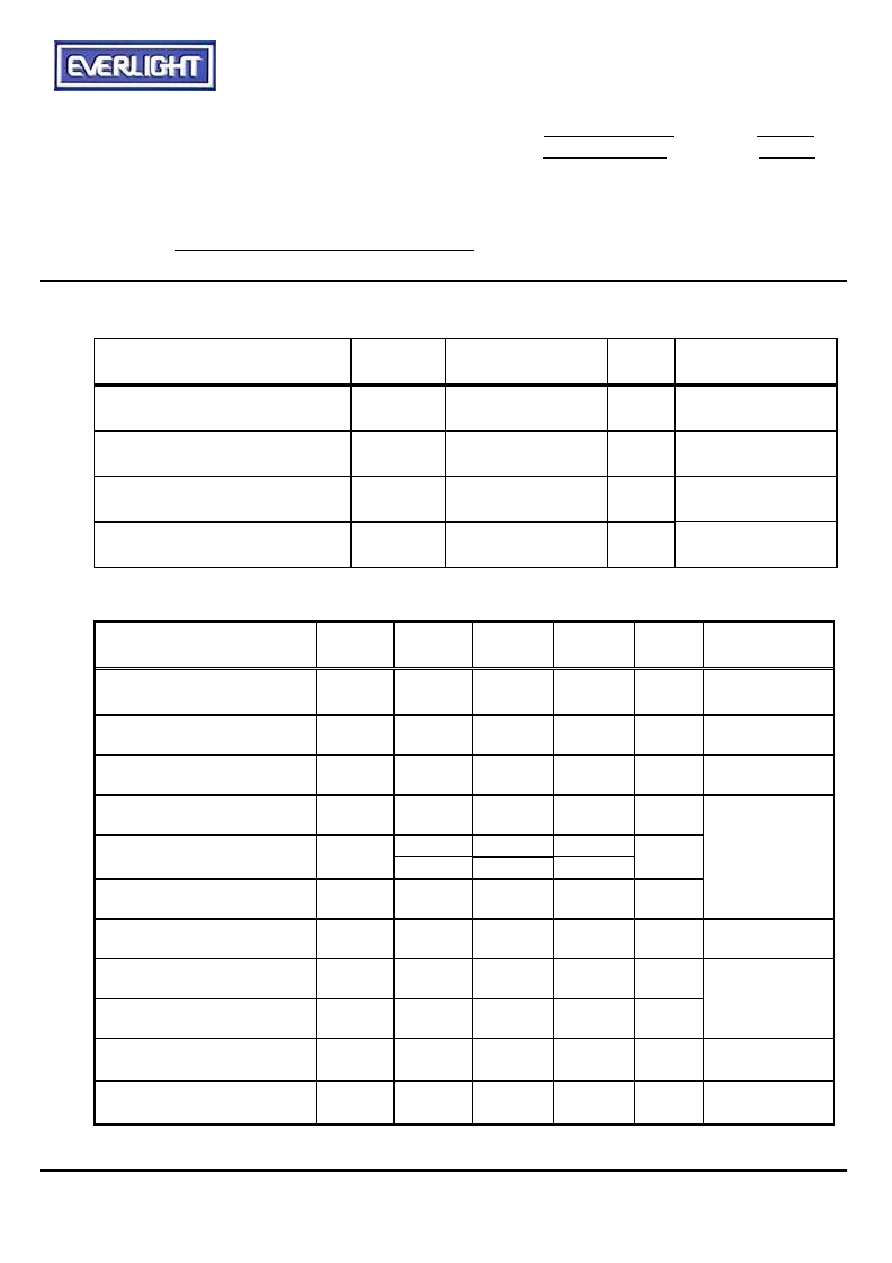
Vcc
0~6
V
�
��
Topr
-20 ~ +75
�
��
Tstg
-20 ~ +85
�
��
Tsol
260
9))-))&(%('
&!** $#:*!"#(*
�
�"#��
!
�
�
! "
Vcc
4.5
5
5.5
V
DC voltage
��
Icc
---
---
3
mA
No signal input
# $�$�%
Fo
---
38
---
KHz
&'()
---
940
---
nm
8
---
---
*+
4
---
---
m
�
,-.,�/0
---
45
---
deg
,-.�0
---
35
---
deg
,)(+')
T
400
---
800
s
1(+')
T
400
---
800
s
�
,)(
V
4.5
---
---
V
1(
V
---
0.2
0.5
V
�
�
�
�
� 9
�
�
�
$�%&
*1:The ray receiving surface at a vertex and relation to the ray axis in the range of
= 0
�
and
=45
�
.
*2:A range from 30cm to the arrival distance. Average value of 50 pulses.
#$
The specified electro-optical characteristics is satisfied under the following
Conditions at the controllable distance.
!
Measurement place
A place that is nothing of extreme light reflected in the room.
"
External light
Project the light of ordinary white fluorescent lamps which are not high
Frequency lamps and must be less then 10 Lux at the module surface.
(Ee
10Lux)
#
Standard transmitter
A transmitter whose output is so adjusted as to
'())'
*
and the output
Wave form shown in Fig.-1.According to the measurement method shown in
Fig.-2 the standard transmitter is specified.
However , the infrared photodiode to be used for the transmitter should be
p=940nm,
=50nm. Also, photodiode is used of PD438B(Vr=5V).
(Standard light / Light source temperature 2856
�
K).
$
Measuring system
According to the measuring system shown in Fig.-3
+
�
�
�
!"
�
�
�
�
�
�
�
�
�
�
� :
�
�
�
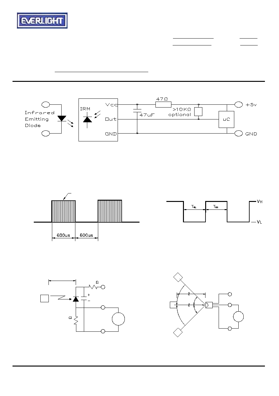
��"��
RC Filter should be connected closely between Vcc pin and GND pin.
Fig.-1 Transmitter Wave Form
D.U.T output Pulse
Fig.-2 Measuring Method
Fig.-3 Measuring System