 | –≠–ª–µ–∫—Ç—Ä–æ–Ω–Ω—ã–π –∫–æ–º–ø–æ–Ω–µ–Ω—Ç: ST78C36 | –°–∫–∞—á–∞—Ç—å:  PDF PDF  ZIP ZIP |

Exar
Corporation 48720 Kato Road, Fremont CA, 94538
∑
(510) 668-7000
∑
FAX (510) 668-7017
∑
www.exar.com
·Á
·Á
·Á
·Á
ST78C36/36A
ECP/EPP PARALLEL PRINTER PORT WITH 16-BYTE FIFO
FEBRUARY 2004
REV. 5.0.1
GENERAL DESCRIPTION
The ST78C36/36A is a monolithic Parallel Port
Interface for use with IBM PC compatible platforms.
Operation as a standard Centronics printer port is the
default, but software may re-configure the device to
support bi-directional IBM PS/2 parallel port,
Enhanced Parallel Port (EPP), or the Extended
Capabilities Port (ECP, as defined by Hewlett Packard
and Microsoft) modes. The ECP modes are
supported by a 16 byte FIFO that may be accessed
by programmed I/O or DMA cycles.
APPLICATIONS
∑
Printers, Scanners and other peripherals
∑
ZIP Drives and back up drives
∑
Printer Server
∑
Embedded Applications
FEATURES
∑
IBM AT bus compatible
∑
Bi-directional port capability
∑
16 byte FIFO for ECP modes
∑
On-chip oscillator (ST78C36A, ST78C36CQ64)
∑
Software selectable Interrupt (5, 7, or 9) and 8-bit
DMA channel (ST78C36CQ64)
F
IGURE
1. ST78C36/36A B
LOCK
D
IAGRAM
D0-D7
-IOR
-IOW
RESET
A0-A2
A10
-CS
AEN
-IOR, -IOW
-IRQx
IOCHRDY
DRQx
PDIR
Da
t
a
bu
s
&
Cont
rol Logic
Re
gis
t
e
r
Select
Lo
gi
c
Int
e
rrupt
Contr
o
l
Lo
gi
c
Printer
Data
Ports
PD0-PD7
Printer
Control
Logic
-STROBE
INIT
-AUTOFDX
-SELCTIN
PE, SELECT
BUSY, -ACK
-ERROR
Printer
FIFO
Registers
Int
e
r C
o
nnec
t
B
u
s L
i
nes
&
Cont
rol si
gnal
s
Clock
&
Timing
Generator
XTAL1
XTAL2
TC
-DACKx
ST78C36/36A
·Á
·Á
·Á
·Á
ECP/EPP PARALLEL PRINTER PORT WITH 16-BYTE FIFO
REV. 5.0.1
2
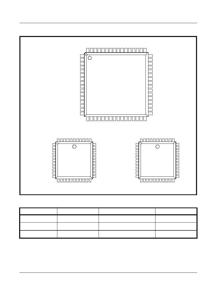
F
IGURE
2. ST78C36/36A P
IN
O
UT
A
SSIGNMENTS
ORDERING INFORMATION
P
ART
N
UMBER
P
ACKAGE
O
PERATING
T
EMPERATURE
R
ANGE
D
EVICE
S
TATUS
ST78C36CJ44
44-PLCC
0
o
C to 70
o
C
Active
ST78C36ACJ44
44-PLCC
0
o
C to 70
o
C
Active
ST78C36CQ64
64-TQFP
0
o
C to 70
o
C
Active
NOTE: PINOUTS NOT TO SCALE. THE 64-TQFP
PACKAGE IS PHYSICALLY SMALLER THAN
THE 44-PLCC PACKAGE.
1
2
3
4
5
6
7
8
9
10
11
12
13
14
15
16
17
18
19
20
21
22
23
24
25
26
27
28
29
30
31
32
48
47
46
45
44
43
42
41
40
39
38
37
36
35
34
33
64
63
62
61
60
59
58
57
56
55
54
53
52
51
50
49
N.C.
-DACK2
DRQ3
-DACK3
D7
D6
D5
D4
D3
D2
D1
D0
AEN
-IRQ9
GND
VCC
GN
D
DR
Q2
TC
PE
-A
C
K
BU
SY
SL
CT
-E
R
R
O
R
VC
C
-I
OR
-I
OW
A1
A0
DR
Q1
N.
C.
N.
C.
N.
C.
-I
R
Q
5
I
O
C
HRD
Y
-I
R
Q
7
XT
AL
1
XT
AL
2
PD
I
R
-C
S
GN
D
RE
SE
T
-S
T
R
O
B
E
-A
U
T
O
F
D
X
IN
IT
-S
L
C
T
I
N
N.
C.
N.
C.
ST78C36CQ64
64-TQFP
GND
-DACK1
A2
PD7
PD6
PD5
PD4
PD3
PD2
PD1
PD0
GND
A10
N.C.
N.C.
N.C.
6
5
4
3
2
1
44
43
42
41
40
7
8
9
10
11
12
13
14
15
16
17
39
38
37
36
35
34
33
32
31
30
29
18
19
20
21
22
23
24
25
26
27
28
DRQ3
-DACK3
D7
D6
D5
D4
D3
D2
D1
D0
AEN
I
O
C
HRDY
-I
R
Q
7
XT
AL
1
XT
AL
2
-C
S
GN
D
R
E
SET
-S
T
R
O
B
E
-
A
UT
O
F
DX
IN
IT
-S
LC
T
I
N
A2
PD7
PD6
PD5
PD4
PD3
PD2
PD1
PD0
GND
A10
TC
PE
-A
C
K
BU
SY
SL
C
T
-
E
RRO
R
VC
C
-I
O
R
-I
O
W
A1
A0
ST78C36ACJ44
44-PLCC
6
5
4
3
2
1
44
43
42
41
40
7
8
9
10
11
12
13
14
15
16
17
39
38
37
36
35
34
33
32
31
30
29
18
19
20
21
22
23
24
25
26
27
28
DRQ3
-DACK3
D7
D6
D5
D4
D3
D2
D1
D0
AEN
I
O
C
HRDY
-I
R
Q
7
CL
O
C
K
PD
I
R
-C
S
GN
D
R
E
SET
-S
T
R
O
B
E
-
A
UT
O
F
DX
IN
IT
-S
LC
T
I
N
A2
PD7
PD6
PD5
PD4
PD3
PD2
PD1
PD0
GND
A10
TC
PE
-A
C
K
BU
SY
SL
C
T
-
E
RRO
R
VC
C
-I
O
R
-I
O
W
A1
A0
ST78C36CJ44
44-PLCC

·Á
·Á
·Á
·Á
ST78C36/36A
REV. 5.0.1
ECP/EPP PARALLEL PRINTER PORT WITH 16-BYTE FIFO
3
PIN DESCRIPTION
N
AME
44-
PLCC
PIN
#
64-
TQFP
PIN
#
T
YPE
D
ESCRIPTION
DATA BUS INTERFACE
A10
A2
A1
A0
29
39
41
40
36
46
53
52
I
Address Select Lines. A10 places the ECP control/status/data ports at
0x400 offset from the -CS decoded address.
D7
D6
D5
D4
D3
D2
D1
D0
9
10
11
12
13
14
15
16
5
6
7
8
9
10
11
12
I/O
Data bus. Bi-directional data port.
-IOR
43
55
I
Active low AT bus I/O Read strobe.
-IOW
42
54
I
-CS
22
24
I
Chip select (active LOW). A LOW at this pin enables the parallel port /
CPU data transfer operation.
IOCHRDY
18
19
O
I/O Channel ready (internal pull-up / three stated active HIGH). This pin
goes low when the device requires addition clock cycles for read and
write.
-IRQ9
-IRQ7
-IRQ5
-
19
-
14
20
18
O
Interrupt Request Lines (three stated active low).
AEN
17
13
I
DMA address enable (active HIGH). When this line is HIGH, the DMA
controller has control of the address bus.
DRQ3
DRQ2
DRQ1
7
-
-
3
63
51
O
Active high AT bus DMA ReQuest for channels 3, 2 and 1 (internal pull-
down three stated active HIGH). A request is generated by bringing a
DRQx line to a HIGH level. A DRQx line is held HIGH until the correspond-
ing DMA acknowledge "DACKx*" line goes LOW.
-DACK3
-DACK2
-DACK1
8
-
-
4
2
47
I
DMA Acknowledge signals for channels 3, 2 and 1 (internal pull-up /three
stated active low).
TC
6
62
I
Terminal Count (active HIGH). The ST78C36 terminates the DMA channel
when a HIGH pulse is detected.

ST78C36/36A
·Á
·Á
·Á
·Á
ECP/EPP PARALLEL PRINTER PORT WITH 16-BYTE FIFO
REV. 5.0.1
4
PRINTER PORT INTERFACE
PD7
PD6
PD5
PD4
PD3
PD2
PD1
PD0
38
37
36
35
34
33
32
31
45
44
43
42
41
40
39
38
I/O
Bi-directional parallel port (three-state) to transfer data in or out of the
ST78C36 parallel port. PD[7:0] are latched during output mode. Output
only for SPP and PPF modes, bi-directional for all other modes.
-STROBE
25
27
O
Data strobe output (internal pull-up / three stated active low). This output
indicates to the printer that valid data is available at the printer port (PD0-
PD7).
-AUTOFDX
26
28
O
Automatic line feed (internal pull-up / three stated active low). When this
signal is low the printer should automatically line feed after each line is
printed.
INIT
27
29
O
Initialize line printer (internal pull-up / three stated active low). When this
signal is low, it causes the printer to be initialized.
-SLCTIN
28
30
O
Line printer select (internal pull-up / three stated active low). When this
signal is low, it selects the printer.
-ERROR
1
57
I
Line printer error (internal pull-up / active low). This is an output from the
printer to indicate an error by holding it low during error condition.
SLCT
2
58
I
Line printer selected (internal pull-up / active high). This is an output from
the printer to indicate that the line printer has been selected.
BUSY
3
59
I
Line printer busy (internal pull-up / active high). An output from the printer
to indicate printer is not ready to accept data.
-ACK
4
60
I
Line printer acknowledge (internal pull-up / active low). This input is
pulsed low by the printer to indicate that data has been accepted success-
fully.
PE
5
61
I
Line printer paper empty (internal pull-up / active high). An output from the
printer to indicate out of paper.
PDIR
21
23
O
Printer port direction indicator. HIGH indicates device is in input mode,
LOW indicates output mode. (ST78C36CJ44 and ST78C36CQ64 only).
SYSTEM SIGNALS
CLOCK/
XTAL1
20
21
I
Crystal oscillator input (ST78C36ACJ44, ST78C36CQ64) or External
clock input (ST78C36CJ44), nominal 24 MHz.
XTAL2
21
22
O
Crystal oscillator output, nominal 24 MHz. ST78C36ACJ44 and
ST78C36CQ64 only.
RESET
24
26
I
System RESET ( active HIGH).
PIN DESCRIPTION
N
AME
44-
PLCC
PIN
#
64-
TQFP
PIN
#
T
YPE
D
ESCRIPTION

·Á
·Á
·Á
·Á
ST78C36/36A
REV. 5.0.1
ECP/EPP PARALLEL PRINTER PORT WITH 16-BYTE FIFO
5
1.0
OVERVIEW
This device is designed around the Hewlett Packard/Microsoft specification for Extended Capabilities Port
Protocol with "ECR mode 100" defined as Enhanced Parallel Port (EPP) mode. The internal timing engines
were designed around a 24 MHz reference, which can be supplied from an external source or by the built-in
oscillator circuit (ST78C36ACJ and ST78C36CQ64 only) with an appropriate crystal.
At system RESET, the device defaults to standard IBM PC compatible Centronics printer mode (output only).
The bi-directional PS/2, EPP, and ECP modes can only be activated by programming the ECR mode field (this
requires address bit A10 = 1, which is outside the normal ISA I/O space).
Optional capabilities of the ECP specification are set as follows:
s
ECP defined interrupts are pulsed, LOW true (Centronics -ACK is non-pulsed, LOW true).
s
PWord size is forced to 1 byte.
s
There is 1 byte in the transmitter that does not affect the FIFO full bit (ECP modes).
s
RLE compression is not supported in hardware.
s
IRQ channel is selectable as 5, 7, or 9 (ST78C36CQ64 only).
s
DMA channel is selectable as 1, 2, or 3 (ST78C36CQ64 only).
s
FIFO THRESHOLD is set at 8 (used only for non-DMA access to the FIFO).
VCC
44
16, 56
Pwr
Power Supply (+5V).
GND
23,30
15, 25,
37, 48,
64
Pwr
Supply Ground.
PORT
ADDRESS
R/W
MODE
FUNCTION
DATA
000
R/W
000, 001
Data Register
ECP-AFIFO
000
W
011
ECP FIFO (Address)
DSR
001
R
All
Status Register
DCR
002
R/W
All
Control Register
EPP-APort
003
R/W
100
EPP Port (Address)
EPP-DPort
004 - 007
R/W
100
EPP Port (Data)
C-FIFO
400
W
010
Parallel Port Data FIFO
ECP-DFIFO
400
R/W
011
ECP FIFO (Data)
T-FIFO
400
R/W
110
Test FIFO
Cnfg-A
400
R
111
Configuration Register A
Cnfg-B
401
R/W
111
Configuration Register B
ECR
402
R/W
All
Extended Control Register
PIN DESCRIPTION
N
AME
44-
PLCC
PIN
#
64-
TQFP
PIN
#
T
YPE
D
ESCRIPTION